A Reference Guide to the Precision Mobile Diagnostic Indicators
Summary: This article takes you through the various diagnostic LEDs and what they mean on the various Precision Mobile workstations.
Instructions
Dell Precision Mobile products have a long history of integrated diagnostic indicators. Indicating at which point during the Power-On Self-Test (POST) a laptop is having issues. These can be:
- Audible beeps
- Power buttons that display different states and colors
- Lock and Status LEDs that change states and colors
- A combination of them all
The following article is a reference guide to the codes available on each model and what those codes mean. These change through the various models and years. These indicators are merely a starting point to narrow down any troubleshooting you carry out to identify the cause of your current issue. You can use this as a starting point to narrow down the proper troubleshooting guide you need. Alternatively, you can contact technical support for further help and they are looking for these indicators as well.
Table of Contents:
- Diagnostic LEDs for the Precision series (2021 to 2025)
- Diagnostic LEDs for the Precision series (2016 to 2020)
- Diagnostic LEDs for the Precision series (2011 to 2015)
- Diagnostic LEDs for the Precision Series (2008 to 2010)
- Diagnostic LEDs for the Precision series (Prior to 2007)
- Glossary of Acronyms
Diagnostic LEDs for the Precision Mobile series (2021 to 2025.)
With this series of laptops, the diagnostic LEDs changed to only use the following method:
This method uses only the Battery LED as an indicator. The diagnostic LED is now the state and color of the Battery LED as it blinks at you.

| Power Source | LED Behavior | System Power State | Battery Charge Level |
|---|---|---|---|
AC Adapter |
|
On (S0) - Off (S5) |
Fully Charged |
AC Adapter |
|
S0 - S5 |
Less than Fully Charged |
Battery |
|
Hibernate (S4) - S5 |
11-100% |
Battery |
|
S4 - S5 |
Less than 10% |


These laptops rely on the battery charge LED blinking an amber or white pattern to determine failures listed in the following table:
The blinking patterns consist of two sets of numbers that represent: (First Group: Amber blinks, Second Group: White blinks).
- First Group: The LED blinks 1 to nine times followed by a brief pause with the LED off at the interval of 1.5 seconds in amber color.
- Second Group: The LED blinks 1 to nine times followed by a longer pause before the next cycle starts again at the interval of 1.5 seconds in white color.
The following table provides information about the amber and white blinking patterns with possible troubleshooting steps:
| LED Flash Sequence | Fault Description | Faults |
|---|---|---|
1,1 |
Trusted Platform Module (TPM) Detection Failure |
Motherboard Error |
1,2 |
SPI Flash Failure |
Motherboard Error |
1, 3 |
Hinge Cable Short tripped OCP1 |
|
1, 4 |
Hinge Cable Short tripped OCP2 |
|
1,5 |
Embedded Controller (EC) unable to program i-Fuse |
Motherboard Error |
1,6 |
EC Code flow errors |
Power Issue |
2,1 |
Central Processor Unit (CPU) |
Possible CPU Failure |
2,2 |
Motherboard Basic input Output Setup (BIOS) |
Motherboard Covers BIOS Corruption, or Read-Only Memory (ROM) Error |
2,3 |
Memory |
No memory or Random Access Memory (RAM) detected |
2,4 |
Memory |
Memory or RAM failure |
2,5 |
Memory |
Invalid Memory Installed |
2,6 |
Motherboard Chipset |
Motherboard or Chipset Error |
2,7 |
Liquid Crystal Display (LCD) |
LCD Failure |
2,8 |
LCD |
Motherboard Failure |
3,1 |
Real-Time Clock (RTC) Power Failure |
Complementary Metal-Oxide Semi-Conductor (CMOS) Battery Failure |
3,2 |
Peripheral Component Interconnect (PCI) or Video |
PCI, or Video Card or Chip Failure |
3,4 |
BIOS Recovery 2 |
Recovery Image Found But Invalid |
3,5 |
Power Rail Failure |
EC ran into power sequencing failure |
3,6 |
System Management BIOS (SBIOS) Flash Corruption |
Flash corruption detected by SBIOS |
3,7 |
Management Engine (ME) Error |
Timeout waiting on ME to reply to Host Embedded Controller Interface (HECI) |
4,1 |
Memory Dual Inline memory modeul (DIMM) power rail failure |
Reset and swap the memory among the available slots. If issue persists memory module failure |
4,2 |
CPU Power Cable Connection issue |
Run the Power Supply Unit (PSU) Bult-In Self-Test (BIST). If issue continues Motherboard, PSU, and cabling failure |
Diagnostic LEDs for the Precision Mobile series (2016 to 2020.)
With this series of laptops, the diagnostic LEDs changed to use two different methods depending on the model of the laptop you have:
- One method uses only the Power LED as an indicator. The Diagnostic LED is now the state of the Power LED and how many times it blinks at you.
- The other method uses only the Battery LED as an indicator. The diagnostic LED is now the state and color of the Battery LED as it blinks at you.

| Power LED State | Description |
|---|---|
|
|
|
Boot Failure - This is a system fault error condition, including the power supply. Only the +5VSB rail on the power supply is working correctly. |
|
Boot Failure - The computer is receiving electrical power, and power supplied by the power supply is normal. A device might be malfunctioning or incorrectly installed. Refer to the table below for Amber Blinking Pattern diagnostics suggestion and possible failures. |
|
The system is in S0 state, the normal power state of a functioning machine. The BIOS will turn the LED to this state to indicate it has started fetching opcodes. |
|
The system is in a low power state, either S1 or S3. This does not indicate a fault condition. |


Example: No Memory is detected. The Power Button LED blinks two times followed by a pause, blinks two times, pause, and so on. This pattern continues until the laptop is turned off.
| LED Behavior | Problem Description | Next Steps |
|---|---|---|
1 |
System Board: BIOS, ROM Failure |
|
2 |
No Memory or RAM detected |
|
3 |
System board, Chipset Error, Clock Failure, Gate A20 Failure, Super I/O Failure, Keyboard controller failure |
|
4 |
Memory or RAM failure |
|
5 |
CMOS battery failure |
|
6 |
Video card or chip failure |
|
7 |
CPU Failure |
|
| Power LED State | Description |
|---|---|
|
|
|
The system is in S0 state, the normal power state of a functioning machine. The BIOS will turn the LED to this state to indicate it has started fetching opcodes. |
|
The system is in a low power state, either S1 or S3. This does not indicate a fault condition. |


- First Group: The Battery LED blinks in Amber up to nine times then pauses for one and a half seconds before running the second group.
- Second Group: The Battery LED blinks in White up to nine times then pauses for three seconds before running the first group again.
Example: No Memory is detected (2,3). The Battery LED blinks two times amber followed by a pause, then blinks three times white, pause, and so on. This pattern continues until the laptop is turned off.
| LED Behavior | Problem Description | Next Steps | |
|---|---|---|---|
| Amber | White | ||
2 |
1 |
CPU Failure |
|
2 |
2 |
System Board: BIOS, ROM Failure |
|
2 |
3 |
No Memory / RAM detected |
|
2 |
4 |
Memory / RAM failure |
|
2 |
5 |
Invalid Memory Installed |
|
2 |
6 |
System board, Chipset Error |
|
2 |
7 |
System board, LCD |
|
3 |
1 |
CMOS battery failure |
|
3 |
2 |
PCI or Video card/chip failure |
|
3 |
3 |
BIOS Recovery 1 |
|
3 |
4 |
BIOS Recovery 2 |
|
3 |
5 |
Power Rail Failure |
|
3 |
6 |
SBIOS Flash Corruption |
|
3 |
7 |
ME Error |
|
This indicates the Battery power management LEDs codes.
| LED Behavior | Battery State |
|---|---|
Blinking Amber and White light (repeated) |
An unauthenticated or unsupported non-Dell AC adapter is plugged to your notebook |
Blinking Amber and Steady White light (repeated) |
Temporary battery failure with AC adapter present |
Constantly blinking Amber |
Fatal battery failure with AC adapter present |
Solid White |
The battery in charge mode with AC Adapter |
Light off |
The battery in full charge mode with AC adapter present |
Light off |
The battery in full charge mode without AC adapter present |
Solid Amber |
Battery charge is critically slow (approx. 30 minutes or less of battery life remaining), without AC adapter present |
Diagnostic LEDs for the Precision series (2011 to 2015)
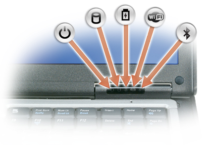
With this series, the Diagnostic LEDs changed to use only the System status LED indicators. The Diagnostic LEDs are now the hard drive activity light, the Battery indicator light, and the Wi-Fi light.
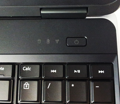
| Icon | Description |
|---|---|
|
HDD activity light - Turns white when the laptop reads or writes data |
|
Battery indicator light - Turns on steadily or blinks to indicate battery charge status |
|
Wi-Fi light - Turns on when wireless networking is enabled |


If the laptop is connected to an electrical outlet, the power and battery light operates as follows:
| LED Behavior | Description |
|---|---|
Solid white color |
Battery charging with AC adapter |
Pulsing white color (slow increase/decrease in illumination) |
The system in Standby, Battery charging with AC adapter |
Off |
System Off, Battery charging with AC adapter (power >90%) |
| Diagnostic LED | Description | Next Step | ||
|---|---|---|---|---|
Hard drive or Storage LED
 |
Battery LED
 |
Wireless LED
 |
||
Blinking |
Solid |
Solid |
The microcontroller is handing control of the system to the processor. This code persists if no processor is detected |
|
Solid |
Blinking |
Solid |
The memory has encountered an error |
|
Blinking |
Blinking |
Blinking |
A system board component is faulty |
|
Blinking |
Blinking |
Solid |
The video card is preventing the system from completing POST |
|
Blinking |
Blinking |
Off |
The keyboard is preventing the system from completing POST |
|
Blinking |
Off |
Blinking |
The USB controller encountered a problem during initialization |
|
Solid |
Blinking |
Blinking |
No SODIMM memory modules are installed |
|
Blinking |
Solid |
Blinking |
The LCD encountered a problem during initialization |
|
Off |
Blinking |
Blinking |
The modem is preventing the system from completing POST |
|
| LED Behavior | Description |
|---|---|
Alternately blinking amber light and blue light |
An unauthenticated or unsupported, non-Dell AC adapter is attached to your laptop |
Alternately blinking amber light with steady blue light |
Temporary battery failure with AC adapter present |
Constantly blinking amber light |
Fatal battery failure with AC adapter present |
Light off |
The battery in full charge mode with AC adapter present |
Blue light on |
The battery in charge mode with AC adapter present |
Diagnostic LEDs for the Precision series (2008 to 2010)
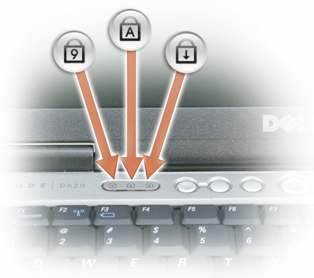
This series had a combination of Keyboard status LEDs with the System status LEDs on the chassis.
These models had a block of keyboard status LEDs on the front of the chassis that either lit up solid Green flashed Green or were Off. Dell Technology has included a table below with what these indicate.

| Icon | Description |
|---|---|
 |
Caps Lock light - Turns on when the Caps Lock is engaged |
 |
Scroll Lock light - Turns on when the Scroll Lock is engaged |
 |
Number Lock light - Turns on when the Number Lock is enabled |
| LED Pattern
(1 2 3) |
LED
Pattern |
Description | Next Step |
|---|---|---|---|
 |
ON-FLASH-FLASH |
No SODIMMs are installed |
|
 |
FLASH-ON-ON |
System board error |
|
 |
FLASH-ON-FLASH |
LCD Panel Error |
|
 |
OFF-FLASH-OFF |
Memory compatibility error |
|
 |
ON-FLASH-ON |
Memory is detected but has errors |
|
 |
OFF-FLASH-FLASH |
Modem Error |
|
 |
FLASH-FLASH-FLASH |
System board error |
|
 |
FLASH-FLASH-OFF |
Option ROM Error |
|
 |
OFF-ON-OFF |
Storage device error |
|
 |
FLASH-FLASH-ON |
Video card error |
|
If the laptop is connected to an electrical outlet, the battery light operates as follows:
- Alternately blinking amber light and blue light: An unauthenticated or unsupported, non-Dell AC adapter is attached to your laptop
- Alternately blinking amber light with steady blue light: Temporary battery failure with AC adapter present
- Constantly blinking amber light: Fatal battery failure with AC adapter present
- Light off: Battery in full charge mode with AC adapter present
- The blue light is on: Battery in charge mode with AC adapter present
To check the battery charge, press and release the status button on the battery charge gauge to illuminate the charge-level lights. Each light represents approximately 20 percent of the total battery charge. For example, if four lights are on, the battery has 80 percent of its charge remaining. If no lights appear, the battery has no charge.
To check the battery health using the charge gauge, press and hold the status button on the battery charge gauge for at least 3 seconds. If no lights appear, the battery is in good condition and more than 80 percent of its original charge capacity remains. Each light represents incremental degradation. If five lights appear, less than 60 percent of the charge capacity remains, and you should consider replacing the battery.
Diagnostic LEDs for the Precision series (Prior to 2007)
Dell Precision mobile workstations have a long history of integrated diagnostic indicators. These can be audible beeps and specific diagnostics LEDs to indicate when during the Power On Self-Test (POST) a laptop is having issues.
These models had a block of keyboard status LEDs on the front of the chassis that either lit up solid Green flashed Green or were Off. Dell Technologies has included a table below with what these indicate.
| Icon | Description |
|---|---|
 |
Caps Lock light - Turns on when the Caps Lock is engaged |
 |
Scroll Lock light - Turns on when the Scroll Lock is engaged |
 |
Number Lock light - Turns on when the Number Lock is enabled |
| Flash Code | LED Pattern | Description | Next Step |
|---|---|---|---|
|
Flash-On-On |
The microcontroller is handing control of the system to the processor. This code persists if no processor is detected. |
|
|
On-Flash-On |
The memory has encountered an error. |
|
|
Flash-Flash-Flash |
A system board component is faulty. |
|
|
Flash-Flash-On |
The video card is preventing the system from completing POST. |
|
|
Flash-Flash-Off |
The keyboard is preventing the system from completing POST. |
|
|
Flash-Off-Flash |
The USB controller encountered a problem during initialization. |
|
|
On-Flash-Flash |
No SODIMMs are installed. |
|
|
Flash-On-Flash |
The LCD encountered a problem during initialization. |
|
|
Off-Flash-Flash |
The modem is preventing the system from completing POST. |
|


If the laptop is connected to an electrical outlet, the battery light operates as follows:
- Solid green — The battery is charging.
- Flashing green — The battery is almost fully charged.
If the laptop is running on a battery, the battery light operates as follows:
- Off — The battery is adequately charged (or the laptop is turned off).
- Flashing orange — The battery charge is low.
- Solid orange — The battery charge is critically low.
Glossary of Acronyms:
See the table for definitions of the acronyms within this article.
| Acronym | Definition |
|---|---|
BIOS |
Basic Input/Output System |
CFG |
Resource Configuration |
CPU |
Central Processing Unit |
DIMM |
Dual In-line Memory Module |
DMA |
Direct Memory Access |
EC |
Embedded Controller |
HECI |
Host Embedded Controller Interface |
LCD |
Liquid Crystal Display |
LED |
Light Emitting Diode |
MBF |
Motherboard Failure |
MBIST |
Memory Built-in Self Test |
ME |
Management Engine |
MEM |
Memory |
NVRAM |
Non-Volatile Random Access Memory |
PCI |
Peripheral Component Interconnect |
POV |
Post-video Activity |
PRV |
Pre-video Activity |
PSU |
Power Supply Unit |
RAM |
Random Access Memory |
RCM |
Recovery Mode |
ROM |
Read Only Memory |
RTC |
Real Time Clock |
S0 |
System Power State S0 – This is the Working State, where your Windows PC is awake. |
S1 |
System Power State S1 – In this sleep state, the CPU is stopped, and your computer is in standby mode. |
S2 |
System Power State S2 – This state is similar to S1 except that the CPU and system cache are lost because the processor loses power. |
S3 |
System Power State S3 – In this state, data is saved to RAM, hard drives, and other hardware are shut down. |
S4 |
System Power State S4 – In this state, RAM and other data are saved to the hard disk. |
S5 |
System Power State S5 - The System is off. |
SBIOS |
Small Board Interface Operating System |
SPI |
Serial Peripheral Interface |
STD |
Boot Hand Off |
STO |
Storage Device |
TPM |
Trusted Platform Module |
USB |
Universal Serial Bus |
VID |
Video |
Follow the instructions if you are seeing a recognizable code. If you have to contact your local support, ensure that you have the code information to hand. The technician needs this information to help you further.
If you are seeing an unrecognizable code, one that is not listed above - then get in touch with your local support straight away.
If you require further assistance, contact Dell Technical Support.