Guide de référence pour les voyants de diagnostic des ordinateurs de bureau Inspiron
Résumé: Cet article est un guide de référence pour les voyants de diagnostic et les codes sonores utilisés sur les différents ordinateurs de bureau tour et tout-en-un (AIO) Inspiron.
Instructions
Guide de référence pour les voyants de diagnostic des ordinateurs de bureau Inspiron
Les ordinateurs de bureau Dell Inspiron utilisent depuis longtemps des voyants de diagnostic intégrés. Ces voyants peuvent prendre la forme de bips sonores, de boutons d’alimentation qui affichent différents états et couleurs, de voyants LED de diagnostic spécifiques ou d’une combinaison de ces derniers. Indique à quel point au cours de l’autotest de démarrage (POST) un appareil rencontre des problèmes.
L’article suivant est un guide de référence des codes disponibles sur chaque modèle et de leur signification. Ces codes changent en fonction des modèles et des années. Ces indicateurs ne sont qu’un point de départ. Un emplacement permettant d’affiner le dépannage effectué en vue d’identifier la cause du problème actuel. Utilisez-le comme point de départ pour restreindre le guide de dépannage approprié. Vous pouvez également contacter le support technique pour obtenir de l’aide. Vos clients recherchent également ces indicateurs.
Voici d’autres ressources sur :
- Compréhension des codes sonores sur les ordinateurs de bureau Dell
- Pourquoi le bouton d’alimentation de mon ordinateur de bureau change-t-il de couleur ou clignote-t-il ?
Sommaire :
- Voyants de diagnostic pour la série d’ordinateurs de bureau Inspiron (2020 à 2025)
- Voyants de diagnostic pour la série d’ordinateurs de bureau Inspiron (2015 à 2019)
- Voyants de diagnostic pour la série des ordinateurs de bureau Inspiron (2008 à 2015)
- Voyants de diagnostic pour la série des ordinateurs de bureau Inspiron (avant 2008)
- Codes sonores des ordinateurs de bureau Inspiron
- Glossaire des acronymes
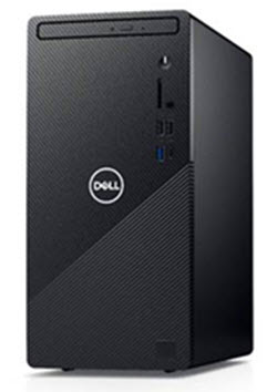
Voyants de diagnostic pour la série d’ordinateurs de bureau Inspiron (2020 à 2025)
Le code de clignotement orange a été remplacé sur les ordinateurs de bureau au format tour. C’est une similitude avec les ordinateurs portables Dell. Le voyant d’alimentation est généralement de couleur blanche.
| Voyant du bouton d’alimentation | État | État de l'alimentation | Description |
|---|---|---|---|
 |
Éteint | S4 ou S5 | Le système est hors tension. Le voyant n'est pas allumé. |
 |
Orange clignotant | - | État initial du voyant à la mise sous tension. Reportez-vous au tableau ci-dessous pour obtenir une suggestion de diagnostic et des indications sur les pannes possibles concernant les codes de voyant orange clignotant. |
 |
Orange fixe | - | Le deuxième voyant LED STATE à la mise sous tension indique que le signal POWER_GOOD est actif. Il est probable que le bloc d’alimentation fonctionne correctement. |
 |
Blanc clignotant | S1 ou S3 | L’état d’alimentation de l’appareil est faible. L’état est S1 ou S3. Ceci n'indique pas une panne. |
 |
Blanc fixe | S0 | Le périphérique est à l’état S0. Cela correspond aux états d'alimentation normaux d'un système qui fonctionne correctement. Le BIOS active ces états de la LED pour indiquer que la récupération des codes de fonctionnement a été initialisée. |
Par exemple : Inspiron 3880, 3881, et ainsi de suite
- Première série : Le voyant de la batterie clignote en orange jusqu’à neuf fois, puis s’interrompt pendant 1,5 seconde avant l’exécution du deuxième groupe.
- Deuxième série : Le voyant de la batterie clignote en orange jusqu’à neuf fois, puis s’interrompt pendant 3 secondes avant de réexécuter le premier groupe.
Exemple : aucune mémoire détectée (2, 3), la LED de la batterie clignote deux fois en orange, effectue une pause, puis clignote trois fois en orange, s’interrompt, et ainsi de suite. Ce schéma se poursuit jusqu’à ce que l’appareil soit mis hors tension.
| Comportement du voyant | Description du problème | Étapes suivantes | |
|---|---|---|---|
| Code clignotant orange | |||
| 1 | 2 | Défaillance irrécupérable de la mémoire Flash SPI |
|
| 2 | 1 | Défaillance du processeur |
|
| 2 | 2 | Carte mère : Échec du code ROM du BIOS |
|
| 2 | 3 | Aucune mémoire ou RAM n’est détectée |
|
| 2 | 4 | Défaillance de la mémoire ou de la RAM |
|
| 2 | 5 | Mémoire installée non valide |
|
| 2 | 6 | Carte mère : erreur du chipset |
|
| 3 | 1 | Défaillance de la pile CMOS |
|
| 3 | 2 | Défaillance de la carte PCI (Peripheral Component Inter-Connect, carte vidéo ou puce) |
|
| 3 | 3 | Récupération du BIOS 1 |
|
| 3 | 4 | Récupération du BIOS 2 |
|
| 3 | 5 | Défaillance du rail d’alimentation |
|
| 3 | 6 | Erreur de volume SPI |
|
| 3 | 7 | Erreur ME |
|
| 4 | 2 | Problème de connexion du câble d’alimentation du processeur |
|
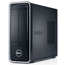
Voyants de diagnostic pour la série d’ordinateurs de bureau Inspiron (2015 à 2019)
Avec les ordinateurs de bureau tour et tout-en-un (AIO) vendus et pris en charge, le voyant d’alimentation clignotant correspond au code sonore standard. Le voyant d’alimentation est généralement de couleur blanche.
| Voyant du bouton d’alimentation | État | État de l'alimentation | Description |
|---|---|---|---|
 |
Éteint | S4 ou S5 | Le système est hors tension. Le voyant n'est pas allumé. |
 |
Orange clignotant | - | État initial du voyant à la mise sous tension. Reportez-vous au tableau ci-dessous pour obtenir une suggestion de diagnostic et des indications sur les pannes possibles concernant les codes de voyant orange clignotant. |
 |
Orange fixe | - | Le deuxième état de LED à la mise sous tension indique que le signal POWER_GOOD est actif. Il est probable que le bloc d’alimentation fonctionne correctement. |
 |
Blanc clignotant | S1 ou S3 | L’état d’alimentation de l’appareil est faible. L’état est S1 ou S3. Ceci n'indique pas une panne. |
 |
Blanc fixe | S0 | L’appareil est à l’état S0. Cela correspond aux états d'alimentation normaux d'un système qui fonctionne correctement. Le BIOS active ces états de la LED pour indiquer que la récupération des codes de fonctionnement a été initialisée. |
Par exemple : Inspiron 660, 3252 à 3655 et 20 à 27 AIO
| Codes sonores de diagnostic | |||
|---|---|---|---|
| État LED | Code sonore | Cause | Solution proposée |
 |
1 | Calcul ou échec de la somme de contrôle de la mémoire morte du BIOS | contactez le support technique. |
 |
2 | Aucun module de mémoire détecté. | Dépannez les modules de mémoire et les logements de mémoire |
 |
3 | Erreur liée au jeu de puces
Échec du test de l’horloge machine Échec de la porte A20 Échec de la puce super E/S Échec du test du contrôleur du clavier |
contactez le support technique. |
 |
4 | Erreur de lecture/écriture de la RAM | Dépannez les modules de mémoire et les logements de mémoire |
 |
5 | Défaillance de l’horloge temps réel | Remplacez la batterie CMOS et contactez le support technique si le problème persiste. |
 |
6 | Échec du test de BIOS vidéo | Exécutez Dell Diagnostics |
 |
7 | Échec du test de la mémoire cache du processeur | contactez le support technique. |
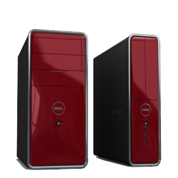
Voyants de diagnostic pour la série des ordinateurs de bureau Inspiron (2008 à 2015)
Cette série utilisait des codes d’états de voyants et des codes sonores pour le bouton d’alimentation. Le voyant d’alimentation est généralement de couleur blanche.
| État LED | État du système | Étape suivante suggérée | |
|---|---|---|---|
| Éteint |  |
L’appareil est hors tension ou n’est pas alimenté | Dépannage d’un : Problème d’absence d’alimentation |
| Orange clignotant |  |
L’ordinateur de bureau est alimenté, un périphérique est peut-être défectueux ou mal installé. | Dépannage d’un : Problème d’échec de l’auto-test de démarrage |
| Orange fixe |  |
L’appareil est en veille. | Appuyez sur une touche du clavier, déplacez la souris ou appuyez sur le bouton d'alimentation pour revenir au fonctionnement normal. Si le problème persiste, écoutez le code sonore. |
| Blanc fixe |  |
L’appareil est sous tension et fonctionne correctement. | Si l’appareil ne répond pas, dépannez : Problème d’absence de démarrage ou d’absence de vidéo |
Inspiron 535 à 710 et Inspiron 19 à un (2310)
| Codes sonores de diagnostic | ||
|---|---|---|
| Code sonore | Cause | Solution proposée |
| 1 | Calcul ou échec de la somme de contrôle de la mémoire morte du BIOS | contactez le support technique. |
| 2 | Aucun module de mémoire détecté. | Dépannez les problèmes suivants : emplacements de mémoire et la mémoire |
| 3 | Erreur liée au jeu de puces
Échec du test de l’horloge machine Échec de la porte A20 Échec de la puce super E/S Échec du test du contrôleur du clavier |
contactez le support technique. |
| 4 | Erreur de lecture/écriture de la RAM | Dépannez les modules de mémoire et les logements de mémoire |
| 5 | Défaillance de l’horloge temps réel | Remplacez la batterie CMOS et contactez le support technique si le problème persiste. |
| 6 | Échec du test de BIOS vidéo | Exécutez Dell Diagnostics |
| 7 | Échec du test de la mémoire cache du processeur | contactez le support technique. |
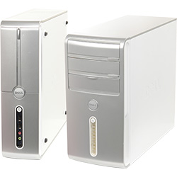
Voyants de diagnostic pour la série des ordinateurs de bureau Inspiron (avant 2008)
Cette série utilisait les états des voyants du bouton d’alimentation et des codes sonores sur les tours et les ordinateurs de bureau tout-en-un (AIO). Le voyant d’alimentation est généralement de couleur bleue.
| État LED | État du système | Étape suivante suggérée | |
|---|---|---|---|
| Éteint |  |
L’appareil est hors tension ou n’est pas alimenté | Dépannez un problème d’absence d’alimentation. |
| Orange clignotant |  |
L’appareil est alimenté, il est peut-être défectueux ou mal installé. | Dépannez un problème d’échec de l’autotest de démarrage. |
| Orange fixe |  |
L’appareil est en panne, y compris le bloc d’alimentation. | Dépannez un problème d’échec de l’autotest de démarrage. |
| Bleu clignotant |  |
L’appareil est en veille. | Appuyez sur une touche du clavier, déplacez la souris ou appuyez sur le bouton d'alimentation pour revenir au fonctionnement normal. Si le problème persiste, écoutez le code sonore. |
| Bleu fixe |  |
L’appareil est sous tension et fonctionne correctement. | Si l’appareil ne répond pas, dépannez : Problème d’absence de démarrage ou d’absence de vidéo |
Inspiron 518s à 530s
| Codes sonores de diagnostic | ||
|---|---|---|
| Code sonore | Cause | Solution proposée |
| 1 | Calcul ou échec de la somme de contrôle de la mémoire morte du BIOS | contactez le support technique. |
| 2 | Aucun module de mémoire détecté. | Dépannez les modules de mémoire et les logements de mémoire |
| 3 | Erreur liée au jeu de puces
Échec du test de l’horloge machine Échec de la porte A20 Échec de la puce super E/S Échec du test du contrôleur du clavier |
contactez le support technique. |
| 4 | Erreur de lecture/écriture de la RAM | Dépannez les modules de mémoire et les logements de mémoire |
| 5 | Défaillance de l’horloge temps réel | Remplacez la batterie CMOS et contactez le support technique si le problème persiste. |
| 6 | Échec du test de BIOS vidéo | Exécutez Dell Diagnostics |
| 7 | Échec du test de la mémoire cache du processeur | contactez le support technique. |
Codes sonores des ordinateurs de bureau Inspiron
En plus des différents types de LED de diagnostic, il existe plusieurs codes sonores sur les modèles de ces ordinateurs de bureau.
Ces codes sont reconnus par différents fabricants et sont les mêmes depuis un certain temps.
La clé de ces codes est présentée dans le tableau ci-dessous.
| Codes sonores de diagnostic | ||
|---|---|---|
| Code | Cause | Solution proposée |
| 1 | Calcul ou échec de la somme de contrôle de la mémoire morte du BIOS | contactez le support technique. |
| 2 | Aucun module de mémoire détecté. | Dépannez les modules de mémoire et les logements de mémoire |
| 3 | Erreur liée au jeu de puces
Échec du test de l’horloge machine Échec de la porte A20 Échec de la puce super E/S Échec du test du contrôleur du clavier |
contactez le support technique. |
| 4 | Erreur de lecture/écriture de la RAM | Dépannez les modules de mémoire et les logements de mémoire |
| 5 | Défaillance de l’horloge temps réel | Remplacez la batterie CMOS et contactez le support technique si le problème persiste. |
| 6 | Échec du test de BIOS vidéo | Exécutez Dell Diagnostics |
| 7 | Échec du test de la mémoire cache du processeur | contactez le support technique. |
Glossaire des acronymes :
Reportez-vous au tableau pour obtenir les définitions des acronymes dans cet article.
| Acronyme | Définition |
|---|---|
| BIOS | Basic Input/Output System (Système de base d’entrée/sortie) |
| CFG | Configuration des ressources |
| Processeur | Central Processing Unit (Processeur) |
| DIMM | Module de mémoire à la volée double |
| DMA | Direct Memory Access (Accès direct à la mémoire) |
| EC | Embedded Controller (Contrôleur incorporé) |
| HECI | Host Embedded Controller Interface (Interface du contrôleur d’hôte intégré) |
| Écran LCD | Liquid Crystal Display (Écran à cristaux liquides) |
| VOYANTS | Light Emitting Diode (Diode électroluminescente) |
| MBF | Panne de la carte mère |
| MBIST | Auto-test intégré de la mémoire |
| ME | Management Engine (Moteur de gestion) |
| MÉM | Mémoire |
| NVRAM | Non-Volatile Random Access Memory (Mémoire vive non volatile) |
| PCI | Peripheral Component Interconnect (Interconnexion de composants périphériques) |
| POV | Activité post-vidéo |
| PRV | Activité pré-vidéo |
| PSU | Power Supply Unit (Bloc d’alimentation) |
| RAM | Random Access Memory (Mémoire vive) |
| RCM | Mode de récupération |
| ROM | Mémoire en lecture seule |
| RTC | Real Time Clock (Horloge temps réel) |
| S0 | État d’alimentation du système S0 : état de fonctionnement, où votre bureau Windows est allumé. |
| S1 | État d’alimentation du système S1 : dans cet état de veille, le processeur est arrêté et votre périphérique est en mode veille. |
| S2 | État d’alimentation du système S2 : cet état est similaire à l’état S1, sauf que le processeur et le cache du système sont interrompus car le processeur n’est plus alimenté. |
| S3 | État d’alimentation du système S3 : dans cet état, les données sont enregistrées sur la mémoire vive. Les disques durs et autres matériels sont arrêtés. |
| S4 | État d’alimentation du système S4 : dans cet état, la mémoire vive et les autres données sont enregistrées sur le disque dur. |
| S5 | État d’alimentation du système S5 : le système est éteint. |
| SBIOS | Small Board Interface Operating System (Système d’exploitation d’interface pour petites cartes) |
| SPI | Serial Peripheral Interface (Interface de périphérique série) |
| STD | Opération de démarrage |
| STO | Périphérique de stockage |
| TPM | Trusted Platform Module (Module de plateforme sécurisée) |
| USB | Universal Serial Bus |
| VID | Vidéo |
s’il s’agit d’un code reconnaissable, suivez les instructions. Assurez-vous d’avoir les informations du code à portée de main lorsque vous contactez le support local. Le technicien a besoin de ces informations pour obtenir de l’aide.
S’il s’agit d’un code méconnaissable, qui n’est pas répertorié ci-dessus, contactez immédiatement le support local.
Cliquez sur le lien suivant pour obtenir de l’aide : contacter le support technique Dell
Informations supplémentaires
Articles recommandés
Voici quelques articles recommandés sur ce sujet qui peuvent vous intéresser.