PowerEdge: Troubleshooting a Server that Does Not Start-No Power, POST, Boot, or Video
Summary: This article provides PowerEdge server troubleshooting for No Power, No POST, No Boot and No Video issues. This includes blade, rack, and tower servers.
Instructions
Table of Content
- Definitions
- Before starting troubleshooting a Dell PowerEdge Server
- Troubleshooting No Power on a Dell PowerEdge Server
- Troubleshooting No POST on a Dell PowerEdge Server
- Troubleshooting No Boot on a Dell PowerEdge Server
- Troubleshooting No Video on a Dell PowerEdge Server
Definitions
No Power
When the power button is pressed, no LEDs including the power button are illuminated. The system has no signs of power. The fans do not spin and make no audible noise. The iDRAC should not respond to pings.
No Video
When the power button is pressed, the system seems to power on. Fans begin to spin and make noise. LEDs around the system including the power button illuminates, but there is no video output on the display.
No POST (Power On Self-Test)
The system powers on and displays video output. During POST, the system goes through a series of checks and startup processes. If the system stops midway through this process and does not finish POST without intervention, this is considered a No POST scenario.
No Boot
The system powers on, displays video output and completes its POST process. The system is expected to boot to its Operating System (OS) if installed. If it does not, this is considered a No Boot scenario.
Diagnose Server Startup Issues:
Duration: 00:01:37 (hh:mm:ss)
When available, closed caption (subtitles) language settings can be chosen using the CC icon on this video player.
Before starting troubleshooting a Dell PowerEdge Server
- When did this problem first occur?
- Is this a 'out of the box' failure (new system), or was it functioning prior?
- Did anything precede the failure in the environment?
- Such as maintenance, a power outage, upgrades, or replacements, inclement weather, and so forth?
- Are any other systems being impacted?
- Specific to the system did anything precede the failure?
- Such as maintenance, a hardware upgrade/change, firmware updates, software changes, and so forth?
- Was any hardware, configuration, or software recently changed?
- Was the system moved, chassis opened, so on where something may have been bumped?
- If the problem occurs randomly, what is the duration or frequency? Any patterns?
A SupportAssist Collection also called a TSR, with debug checked/enabled should be collected from the iDRAC. This may not be possible in some situations, such as No Power.
- Export a SupportAssist collection using iDRAC9/IDRAC10
- Export a SupportAssist Collection using iDRAC7 and iDRAC8
For information about troubleshooting errors, see the Owner's Manual for the specific model.
Return to Table of Content
Troubleshooting No Power on a Dell PowerEdge Server
-
Check input power
The system power supplies take input power and convert it to power that is consumable by system components. A power supply unit creates two different types of system component power:
- Main power - used by the server to power on and function
- Auxiliary (flea) power - this is created anytime the input power is valid. It is used to power any component which must run when the system is off, such as the control panel (power button), iDRAC, specific network, so on
Goal:
- Confirm that input power is properly connected to the system and the system is receiving auxiliary power.
- Confirm that the power supplies do not have a problem preventing system power on.
Troubleshooting:
Make sure power cables are installed in at least one of the power supplies (if the server is equipped with more than one).
Hot Swap Power Supplies:
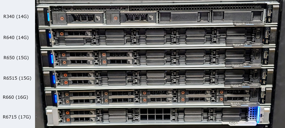
For PowerEdge 14G through 17G systems with hot-swap power supplies, these can be removed without opening the chassis and depending on system configuration are called hot-swap power supplies. The handle illumination, or lack of it, provides critical information:
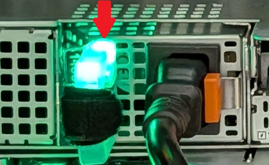
Check your models Installation and Service Guide for details, but below are the general guidelines:
- Off - No input power or invalid input power
- Blinking Amber - the power supply has a fault condition
- Blinking green and then off –Incorrect input power voltage, mismatched power supplies, or mismatched voltage between power supplies
- Solid Green - the PSU is ready to power on the system
If the power supply is off or blinks green and then turns off, this is likely an environmental issue rather than a power supply failure.
Recommendations:
- Remove the power supply and check the label for its voltage requirements. Confirm that the outlet is providing voltage in that labeled range.
- Try a different power cable.
- Try a different outlet.
- Bypass the UPS, power strip, PDU, so on by using a nearby outlet.
- If equipped, try the other Power Supply to confirm the behavior is the same
If the power supply is solid green or blinking amber:
Auxiliary (flea) power is online, so iDRAC should be accessible. The Lifecycle Log and SupportAssist Collection (TSR) provide further guidance.
Cabled Power Supplies:
For PowerEdge 14G through 17G systems with cabled power supplies, the power supplies are always nonredundant and cannot be removed without opening the chassis.
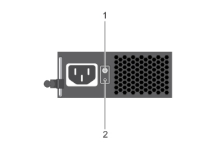
Press the Diagnostic Button on the power supply (2 on above figure). If the LED turns green, the power supply is connected to a valid power source. If it does not power on:
- Try a different power cable.
- Try a different outlet.
- Bypass the UPS, power strip, PDU, and so on, by using a nearby outlet.
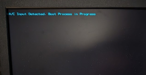
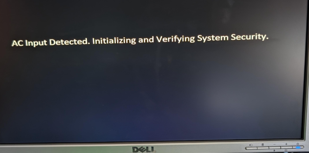
Video output when connecting power:
- In newer firmware, video output was added to identify that power has been supplied to the system and iDRAC is working to boot.
Example figures:
Check for iDRAC boot:
Once the iDRAC is booted, it is possible to gather a SupportAssist Collection (TSR) over the network (if the iDRAC is configured) or using IDRAC Direct
- IDRAC is powered using Auxiliary(flea) power from the server's power supply units. If one or more of the PSUs is showing green or blinking amber status, the iDRAC is powered and attempts to boot.
- PowerEdge 15G and later, iDRAC boots before the system can power on.
Check System Health LEDs:
System health LED location and meaning may vary, see your models Installation and Service Guide for more details. However the below can be used as a general indication:
- Solid blue - System is healthy
- Blinking blue - System identification mode enabled (System ID button pressed on server or in iDRAC)
- Solid or blinking amber - System in fail-safe mode or has an error or fault
For more details and figures, refer to the article: PowerEdge: How to Determine if iDRAC is Available
If the system health LED is online on the front or back of the server, iDRAC should be booted and accessible. The iDRAC should be leveraged for further review. There are multiple ways to access iDRAC:
- Using iDRAC Direct (requires the applicable USB cable) - PowerEdge: How to Use the iDRAC Direct Feature
- Using the IDRAC network port
- Even if the iDRAC was not previously configured, it can be accessed using its default IP address (typically 192.168.0.120) or its DHCP address.
- Using the system LOM if it was configured prior.
Troubleshooting System Health LED not turning on
If the system LED does not turn on, open the chassis and look for any LED’s on the motherboard.
If all motherboard LEDs are OFF but the power supply LED is on (see above), there could be a problem with the power supply or power distribution board (if applicable).
If motherboard LEDs are present, then power is auxiliary (flea) power is being provided to the system and the iDRAC should boot.
Power button
Once the power button is pressed in the system attempts to power on. During power up any errors are displayed in:
- The Lifecycle Log
- The SupportAssist Collection (TSR) captures the motherboard diagnostic LEDs
- The motherboard diagnostic LEDs can also be checked manually by opening the chassis
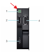
Pictures of power button locations:
|
16G systems |
17G systems |
|
|
|
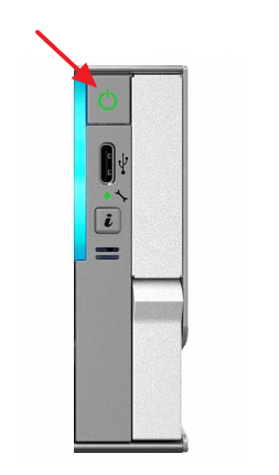
The power button LED has three states:
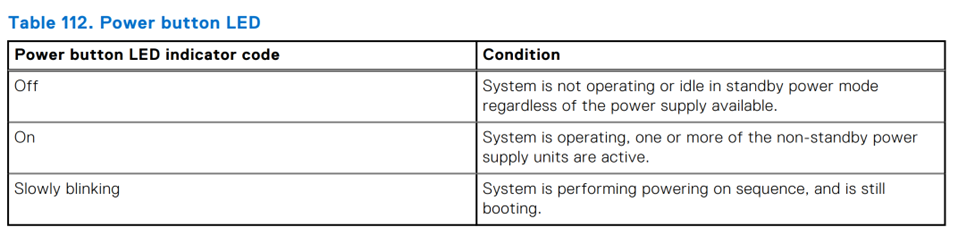
The system power up and initialization sequence indicated by slow blinking may take several minutes to complete. The slow-blinking state indicates that the system is trying to power on but waiting for additional firmware-related power checks to complete. During this time, the screen should also show the message 'Please wait while system is initializing...'.
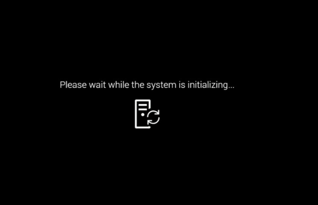
Troubleshooting Please wait while the system is initializing:
- From iDRAC, gather a SupportAssist Collection and review the Lifecycle Log for any critical errors. If present, they may point to why the system is failing to turn on. There are specific safeguards that may trigger to keep a system from booting to avoid damage.
- If the iDRAC is unavailable, check inside the chassis for any missing or loose cables or components.
Troubleshooting if the system shuts off:
- If after pressing the power button the system shuts down immediately or after a few seconds, the system has encountered a power up fault. The system health LED should go amber.
- The iDRAC captures which component or components have faulted in the Lifecycle Log.
Once the power button has gone solid green and stays on, the system is released from reset and begins its POST sequence.
No Power on Your PowerEdge Server:
Duration: 00:01:29 (hh:mm:ss)
When available, closed caption (subtitles) language settings can be chosen using the CC icon on this video player.
Troubleshooting No POST
During POST (also called UEFIBIOS) progress and errors are shown in several ways:
- On the local video output
- In the SupportAssist Collection
- Using the iDRAC UI or IPMITOOL
Local display
If issues are encountered, the POST sequence attempts to output these to the screen using error codes with a prefix of HWC and UEFI.
Further details on these error codes can be found in the "PowerEdge Servers Error and Event Messages Reference Guide"
SupportAssist Collection and Lifecycle Log
Error codes of HWC and UEFI are also written to the Lifecycle Log which can be checked using the iDRAC. The SupportAssist Collection (Make sure to check/enable debug) also contains this and other information which is useful for further review with your service provider.
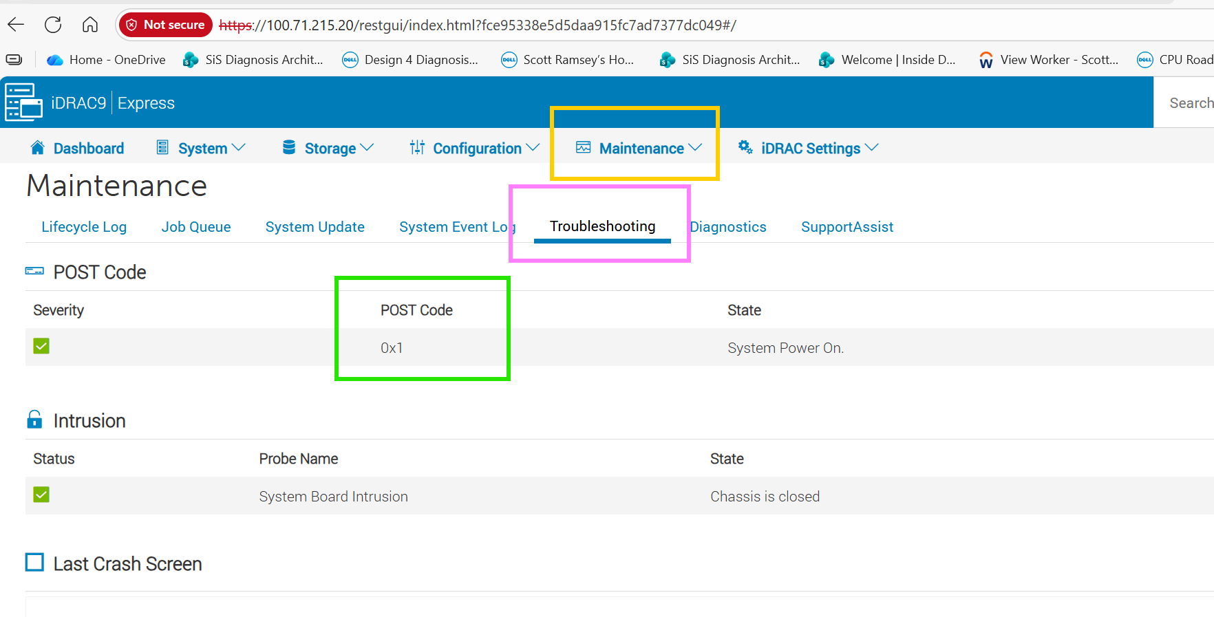
POST Codes
At various points during the system boot process, the BIOS notifies the iDRAC of boot progress and error conditions.
Checking using IDRAC interface:
Checking using IPMITOOL
If a system stops responding, it is possible to pull the BIOS progress code using IPMI tool.
ipmitool -I lanplus -H <IDRACIP> -U <Username> -P <Password> raw 0x30 0x27 0x01
What the POST Codes mean:
The codes are broken into the below:
- Progress code - checkmark on where the system has progressed in boot
- Error codes - when BIOS detects an error condition and potentially stops
Progress Codes:
|
Code |
Meaning |
|
0x50 |
At F1/F2 prompt |
|
0x51 |
At F1/F2 prompt with no bootable devices |
|
0x52 |
Entered system setup |
|
0x53 |
Entered boot menu |
|
0x54 |
Entered system service mode |
|
0x55 |
CSIOR - collecting system inventory |
|
0x56 |
Entered LC. |
|
0x7e |
Booted for UEFI OS |
|
0x7F |
Booted to OS (legacy) |
These codes indicate where UEFIBIOS has booted to.
Error codes:
Error codes can vary based on model and generation. Contact support and reference this article and POST code for more information. It would also help to have:
- Screenshot of the POST code
- A SupportAssist Collection with debug option checked
If no actionable errors are provided on the screen or in iDRAC’s Lifecycle Log:
- Complete a power drain on the system - PowerEdge: How Do I Reset and Power Drain My Server
- If the server now completes POST, monitor the system and check for any available firmware updates.
- If the server still does not complete POST and still no actionable errors are provided on the screen or in iDRAC’s Lifecycle Log, go to the next step.
- Label and disconnect all cables, USB devices, tape drives, SD cards, CDs, and so on from the system except for an input power cable, monitor cable (if using), and iDRAC network cable (if using).
- Restart the system.
- If the server now completes the POST, plug the cables and devices back in one at a time until the issue is isolated.
- If the server still does not complete POST and still no actionable errors are provided on the screen or in iDRAC’s Lifecycle Log, go to the next step.
- Remove all third party components and parts.
- If the server now completes POST, reinstall the components one at a time until the issue is isolated.
- If the server still does not complete POST and still no actionable errors are provided on the screen or in iDRAC’s Lifecycle Log, go to the next step.
- Unseat all drives (check front and back) from the system.
- Restart the system.
- If the server now completes the POST, plug the drives back in one at a time until the issue is isolated.
- This may also indicate an issue with an applicable RAID/drive controller.
- If the server still does not complete POST and still no actionable errors are provided on the screen or in iDRAC’s Lifecycle Log, go to the next step.
- Remove PCI cards including NDC, OCP, PERC, fPERC, and so on if applicable.
- If the server now completes POST, reinstall the components one at a time until the issue is isolated.
- If the server still does not complete POST and still no actionable errors are provided on the screen or in iDRAC’s Lifecycle Log, go to the next step.
- Test with minimum to post. This is usually the power supply unit (PSU), motherboard, CPU 1, one stick of RAM, and the backplane. Full details for the minimum to post can be found in your Owner's Manual under Minimum to POST.
- If the server now completes POST, reinstall the components one at a time until the issue is isolated.
- Clear pictures of the minimum post configuration should be collected to ensure that the true minimum to post was tested during the isolation process. Some components, cables, risers, and so on within the server are often missed during the troubleshooting process and capturing visual confirmation using a picture helps ensure that everyone is on the same page.
- Note: For MultiProcessor, Multi-DIMM, or Multi-PSU configurations, if the server is not posting in a minimum to post configuration the CPU (typically CPU1), single DIMM (typically A1), and PSU should be swapped out with parts that were previously removed from the server to verify that they are not the cause of the no post. For example, testing CPU2 in the CPU1 socket with the original CPU1 removed from the server or swapping out DIMM A1 with a different DIMM that was previously removed from the server.
No POST on Your PowerEdge Server:
Duration: 00:04:14 (hh:mm:ss)
When available, closed caption (subtitles) language settings can be chosen using the CC icon on this video player.
Troubleshooting No Boot on a Dell PowerEdge Server
The server powers on completes POST and when the Operating System should be starting you instead see 'No Boot Device Available' or related message.
Manually select boot device:
- Restart the system.
- Press F11 during POST to enter Boot Manager.
- Select the required boot device.
If the system now boots into the operating system, the hardware is fine, and there is a boot misconfiguration in the BIOS settings.
You can change the boot order setting permanently in the System Setup to boot from the drive first. To change this:
- Restart the system.
- Press F2 during system start to enter the System Settings.
- Change the Boot Sequence in the Boot Settings.
- Leave the menu using Exit in the upper right corner of the screen.
No Boot on Your PowerEdge Server:
Duration: 00:01:45 (hh:mm:ss)
When available, closed caption (subtitles) language settings can be chosen using the CC icon on this video player.
Troubleshooting No Video on a Dell PowerEdge Server
If there are indications that the server is or has booted, but the system has no video output:
- Check iDRAC for any errors and gather a SupportAssist Collection (TSR)
- If the iDRAC License allows Virtual Console, check to see if it is correctly displaying video output
- A trial iDRAC license that enables the Virtual Console can be leveraged.
- Check that monitor input selection is set to the correct input.
- Test the monitor and same video cable on a different working system using the same power outlet.
- If the issue is isolated to the monitor, attempt to swap cables or use a different monitor.
- If using a KVM, ensure that the correct system is selected.
- Bypass any KVM and test directly on the front and the rear output of the server.
- Try a different video output port on the system (if available). See your models Installation and Service Guide for details.
- Confirm that the monitor cable is connected to the correct video output on the server. If an add-on video card has been installed, be sure that the monitor cable is connected to it rather than the integrated video source.
- Power drain the server then check for video on POST to rule out the Operating System. For more information, see article How do I Reset and Drain the Power of my Dell PowerEdge Server?
- Ensure that the monitor cable is connected to the first video card based on PCIe enumeration when the embedded video controller is set to disabled.
If the system is still showing no video from the front panel and the rear, contact Dell Support.
No Video on Your PowerEdge Server:
Duration: 00:02:00 (hh:mm:ss)
When available, closed caption (subtitles) language settings can be chosen using the CC icon on this video player.