Openshift: Network validation failed during cluster deployment
Summary: If user set MTU for management traffic during cluster deployment or node addition process, corresponding MTU on physical switch ports needs to be set as well, otherwise network validation will fail. ...
This article applies to
This article does not apply to
This article is not tied to any specific product.
Not all product versions are identified in this article.
Symptoms
Cluster deployment scenario
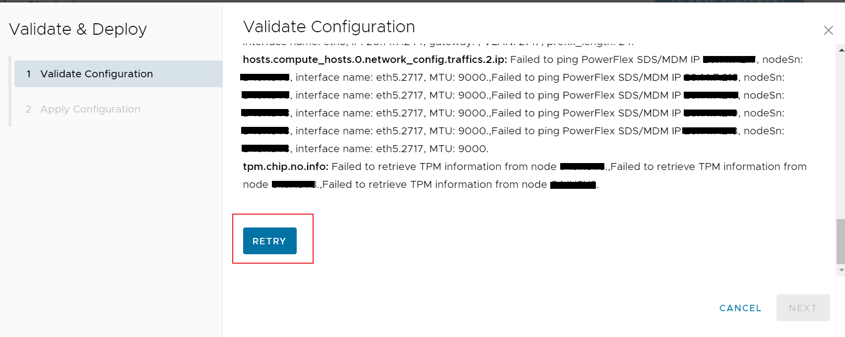
Symptom1: Network validation fails and shows error like: "Failed to execute host ping validation, nodeSn: xxxxxxx, interface name: eth5, targetIp: x.x.x.x, MTU:9000".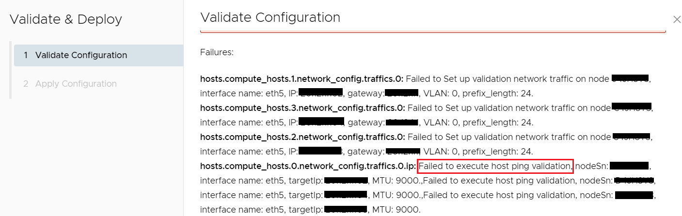
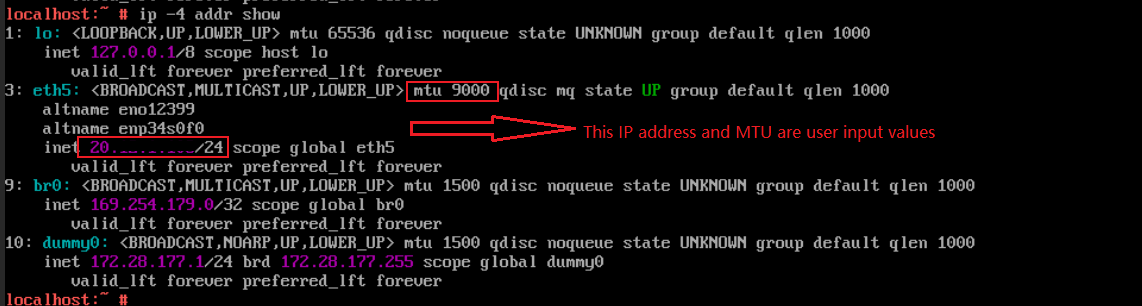
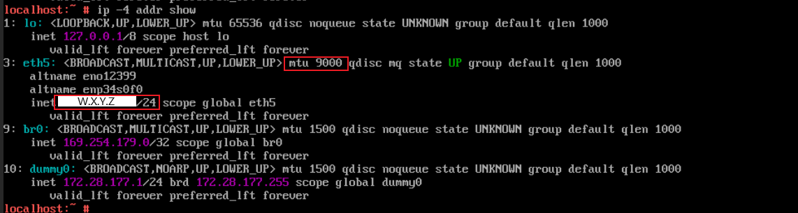
Symptom2: On secondary nodes, there should be NO IPv4 address on the management interface, and the MTU should be default value 1500. But after validation fails, the IP and MTU are changed to user UI input values. Go to the secondary node's console via iDrac, confirm this by command: "ip -4 addr show", for example:

Note: If it is not the case, then this KB does not apply to your issue, the validation failure should be caused by other reasons.
Symptom3: Check the "mcp-bootstrap-controller" log, we can see API failed due to "net/http: TLS handshake timeout" after set the MTU.


Symptom4: Perform ping test from primary node to secondary node by command:
ping [-I source interface] -c 5 [-s packet size] [target IP] -M do
If the packet size is smaller than the switch port's MTU, ping test passes.
If the packet size exceeds the switch port's MTU, ping test fails.
For example:
- ping test with packet size 1500
ping -I eth5 -c 5 -s 1472 <secondary node IP> -M do
- ping test with packet size 9000
ping -I eth5 -c 5 -s 8972 <secondary node IP> -M do
Node addition scenario
Symptom1: Validation fails and shows error like: "Node xxxxxxx cannot communicate with IP x.x.x.x and packet size 9000 on interface NIC.Slot-6-1-1 to IP x.x.x.x in management network using VLAN 0."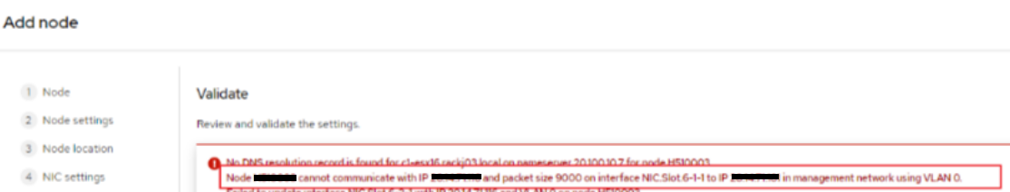
Symptom2: On the to-be-added new nodes, there should be NO IPv4 address on the management interface, and the MTU should be default value 1500. But after validation fails, the IP and MTU are changed to user UI input values. Go to the new node's console via iDrac, confirm this by command: "ip -4 addr show", for example:
Note: If it is not the case, then this KB does not apply to your issue, the validation failure should be caused by other reasons.
Symptom3: Check the "mcp-bootstrap-controller" log, we can see API failed due to "net/http: TLS handshake timeout" after set the MTU, for example:
[ERROR] <7302> bootstrap_agent_connector.go CreateAsyncTask() (392): Error occured when creating aync task request with Bootstrap Agent: Pos "https://[fe80::x:x:x%!n(MISSING)et1]:9445/rest/apex-cp/v1/commands/ping": net/http: TLS handshake timeout
Symptom4: Perform ping test from primary node to the to-be-added new node by command:
ping [-I source interface] -c 5 [-s packet size] [target IP] -M do
If the packet size is smaller than the switch port's MTU, ping test passes.
If the packet size exceeds the switch port's MTU, ping test fails.
For example:
- ping test with packet size 1500
ping -I eth5 -c 5 -s 1472 <to-be-added new node IP> -M do
- ping test with packet size 9000
ping -I eth5 -c 5 -s 8972 <to-be-added new node> -M do
Cause
During cluster deployment or node addition process, the network validation will validate the MTU and configure the user input MTU to the network NIC on all nodes.
If the switch MTU is smaller than the user input MTU, the API call between primary node and secondary node will fail at HTTPS TLS/SSL handshake step because the HTTPS handshake packets sent out from primary node exceeds the MTU on the switch port, so the packets will be dropped by the switch.
If the switch MTU is smaller than the user input MTU, the API call between primary node and secondary node will fail at HTTPS TLS/SSL handshake step because the HTTPS handshake packets sent out from primary node exceeds the MTU on the switch port, so the packets will be dropped by the switch.
Resolution
In summary, the resolution includes 4 steps:
Below are the detailed steps:
Cluster deployment scenario resolution:
1. Change the MTU back to default value 1500 on all nodes:
2. Clean up the IP settings on all the secondary nodes. (No need to execute on primary node)

3. Configure the MTU on physical switch to allow network traffic to pass with the expected MTU.
4. Address the issue on the Web UI and retry network validation.
Option2: Click the 'Node Settings' page, address all the highlighted issues in this page and click 'Next' to switch to 'Network Settings' Page.
Node addition scenario resolution:
1. Change the MTU back to default value 1500 on all the to-be-added new nodes:
2. Clean up the IP settings on all the to-be-added new nodes.
3. Configure the MTU on physical switch to allow network traffic to pass with the expected MTU.
4. Address all the highlighted issues on the Web UI, input the tested correct MTU and retry network validation.
- Recover MTU to default value on all nodes.
- Clean up the user input IPv4 on secondary nodes (cluster deployment scenario) or to-be-added new nodes (node addition scenario).
- Configure the switch and PowerFlex appropriately to allow network traffic to pass at the expected MTU.
- Input correct MTU on cluster deployment or node addition UI and retry validation.
Below are the detailed steps:
Cluster deployment scenario resolution:
1. Change the MTU back to default value 1500 on all nodes:
- Login to the node console via iDRAC
- Run command "cat /etc/mcp-bootstrap-utility/management_eth_interface.yaml" to identify the first_management_data_interface.
For example:
first_management_data_interface:
  name: eth5 # this is the management interface
  mac:
  vendor: 0x8086
multicast_interface:
  name: eth5
  vlan: 0
- Set the MTU to 1500 via command "ip link set dev [management interface] mtu 1500"
For example:
ip link set dev eth5 mtu 1500
- Run command "ip -4 addr show" to make sure the MTU is set to 1500.
2. Clean up the IP settings on all the secondary nodes. (No need to execute on primary node)
- Login to the node console via iDRAC.
- Run command "cat /etc/mcp-bootstrap-utility/management_eth_interface.yaml" to identify the management interface.
- Check the ip settings via command "ip -4 addr show".
For example:
There should be an IP (W.X.Y.Z in above screenshot) which is the management IP input by user.
- Remove the IP via command "ip addr del [ip/prefix] dev [management interface]"
For example:
ip addr del W.X.Y.Z/24 dev eth5
- Run command "ip -4 addr show" again to make sure the management IP is removed.
3. Configure the MTU on physical switch to allow network traffic to pass with the expected MTU.
- The MTU should be configured properly on all the ports which the traffic will go through, including the ports connected to NICs and the ports between switches.
- The MTU setting for the switch should be larger than the node MTU. For example, if the node MTU setting is 9000, the switch MTU setting should be 9216.
- If use LACP for the bond, the MTU should be configured for the port channel.
- After MTU is configured, test the MTU with ping command.
Note: If use 2 bonds, they may have different MTU. Need to make sure the corresponding switch ports are configured with correct MTU.
4. Address the issue on the Web UI and retry network validation.
- Go to the 'Network Settings' page
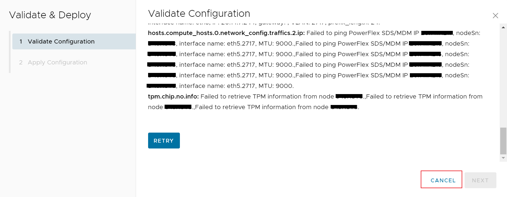
- Click 'Cancel' on 'Validate & Deploy' Page
- Switch to the 'Network Settings' page, if encounter issues when accessing this page, there are 2 options to workaround:
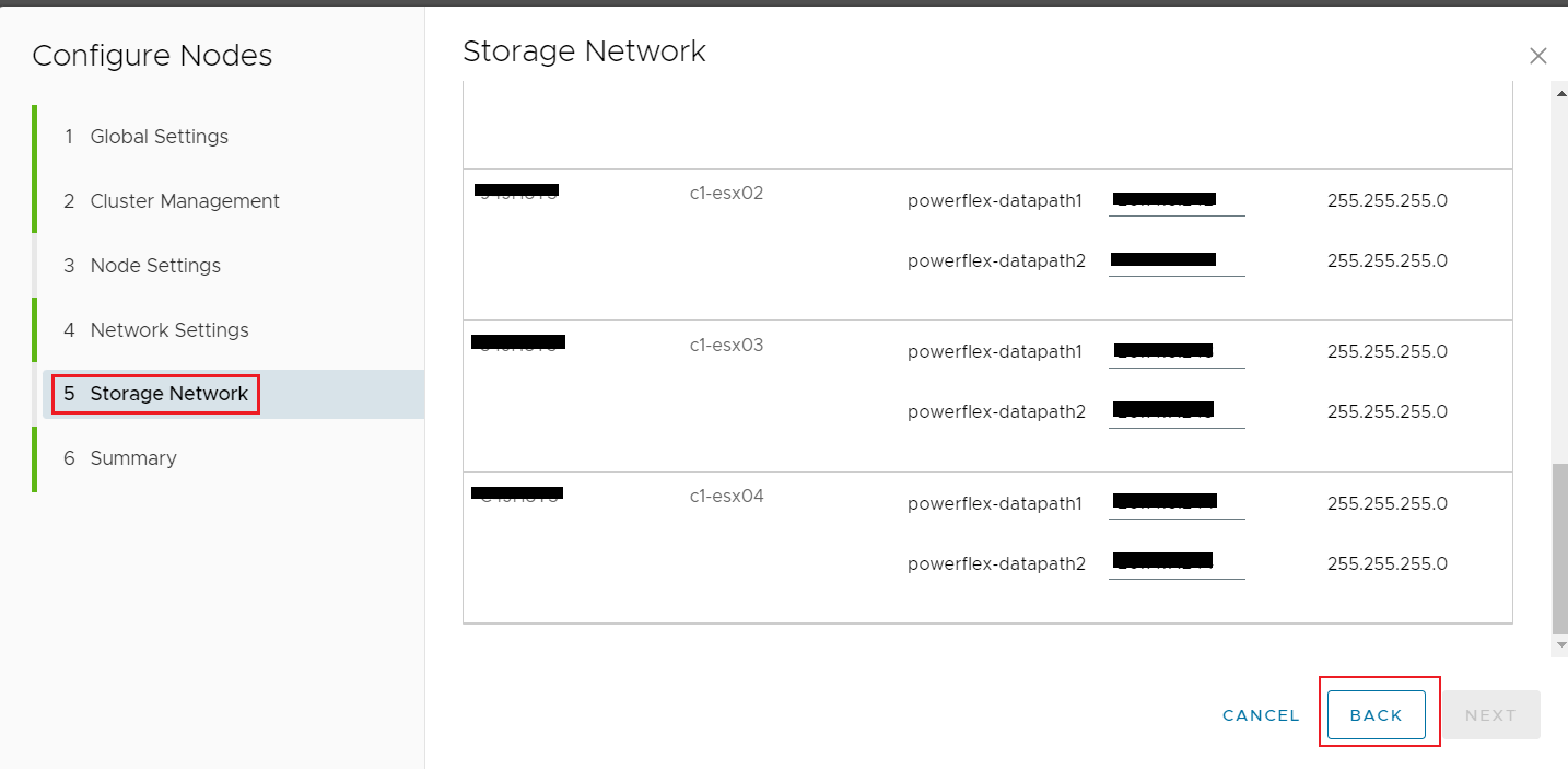
Option1: Click the 'Storage Network' page, address all the highlighted issues in this page and click 'Back' to switch to 'Network Settings' page.
For example:
For example:
Option2: Click the 'Node Settings' page, address all the highlighted issues in this page and click 'Next' to switch to 'Network Settings' Page.
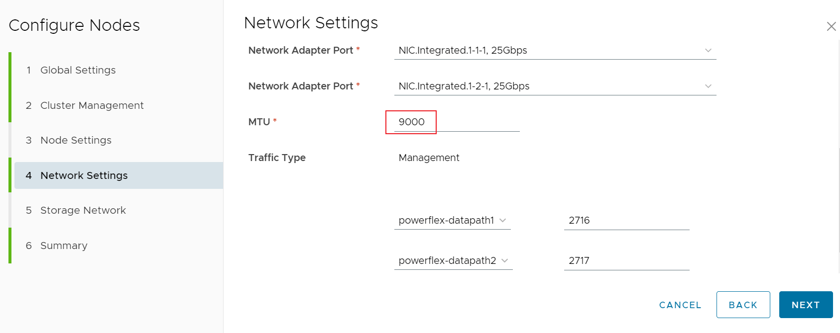
- Set correct MTU in 'Network Settings' page.
Input the correct MTU, means the switches are tested that network traffic can pass with this MTU.
For example input node MTU 9000:
- Confirm all configurations on the Web UI are correct, then retry validation.
Node addition scenario resolution:
1. Change the MTU back to default value 1500 on all the to-be-added new nodes:
- Login to the node console via iDRAC
- Run command "cat /etc/mcp-bootstrap-utility/management_eth_interface.yaml" to identify the first_management_data_interface.
For example:
first_management_data_interface:
  name: eth5 # this is the management interface
  mac:
  vendor: 0x8086
multicast_interface:
  name: eth5
  vlan: 0
- Set the MTU to 1500 via command "ip link set dev [management interface] mtu 1500"
For example:
ip link set dev eth5 mtu 1500
- Run command "ip -4 addr show" to make sure the MTU is set to 1500.
2. Clean up the IP settings on all the to-be-added new nodes.
- Login to the node console via iDRAC.
- Run command "cat /etc/mcp-bootstrap-utility/management_eth_interface.yaml" to identify the management interface.
- Check the ip settings via command "ip -4 addr show".
For example:
There should be an IP (W.X.Y.Z in above screenshot) which is the management IP input by user.
- Remove the IP via command "ip addr del [ip/prefix] dev [management interface]"
For example:
ip addr del W.X.Y.Z/24 dev eth5
- Run command "ip -4 addr show" again to make sure the management IP is removed.
3. Configure the MTU on physical switch to allow network traffic to pass with the expected MTU.
- The MTU should be configured properly on all the ports which the traffic will go through, including the ports connected to NICs and the ports between switches.
- The MTU setting for the switch should be larger than the node MTU. For example, if the node MTU setting is 9000, the switch MTU setting should be 9216.
- If use LACP for the bond, the MTU should be configured for the port channel.
- After MTU is configured, test the MTU with ping command.
Note: If use 2 bonds, they may have different MTU. Need to make sure the corresponding switch ports are configured with correct MTU.
4. Address all the highlighted issues on the Web UI, input the tested correct MTU and retry network validation.
Additional Information
Note: If the node management network is using the same vLAN (3939) with the node discovery network, network validation will also fail, this is a misconfiguration and not supported case.
Affected Products
APEX Cloud Platform for Red Hat OpenShiftArticle Properties
Article Number: 000217473
Article Type: Solution
Last Modified: 20 فبراير 2026
Version: 4
Find answers to your questions from other Dell users
Support Services
Check if your device is covered by Support Services.