Dell Precision Workstation R7610 Visual Guide
Summary: This article provides a Visual Guide to your Dell Precision Rack Workstation R7610
This article applies to
This article does not apply to
This article is not tied to any specific product.
Not all product versions are identified in this article.
Symptoms
This article provides a Visual Guide to your Precision Workstation R7610
Table of Contents:
 NOTE: For a more detailed description about each location, please go to the system manuals at www.dell.com/manuals
1. Chassis Overview
The image below displays the inside view of the of the precision rack after the front bezel and the system cover have been removed.

| 1 | Control Panel | 2 | Plastic Cable Cover |
| 3 | Cooling Shroud | 4 | Fan Bracket |
| 5 | System Fans | 6 | Power Distribution Unit |
| 7 | Center Expansion Card Cage | 8 | Outer Expansion Card Cage |
| 9 | Coin-Cell Battery | 10 | SAS Backplane |
| 11 | Front Chassis Assembly | 12 | Hard Drive (1 of up to 6) |
| 13 | Optical Drive |
2. Front View
The image below displays the precision rack after the front bezel has been removed.

| 1 | Power Button, Power LED | 2 | System Identification Button |
| 3 | System Identification Light | 4 | Drive Activity light |
| 5 | Network Link Integrity Lights (2) | 6 | Diagnostic LEDs (1234) |
| 7 | USB 2.0 connectors (2) | 8 | Optical CD/DVD Drive |
| 9 | Hard Drive Bays (6) |
3. Rear View

| 10 | Expansion Card Slots | 11 | USB 2.0 Connectors (4) |
| 12 | Network Adapter Connectors (2) | 13 | Network Link Integrity Light |
| 14 | Network Activity Light | 15 | Serial Port |
| 16 | Audio Line Out | 17 | Audio Line In/ Mic |
| 18 | System Identification Light | 19 | System Identification Button |
| 20 | Remote System Identification Light Connector | 21 | Second Power Supply Bay (Optional) |
| 22 | Power Connector |
4. Front Bezel Removal
1. Unlock the front bezel using the supplied key.
2. Lift the bezel release tab and gently pull the front bezel away from the system.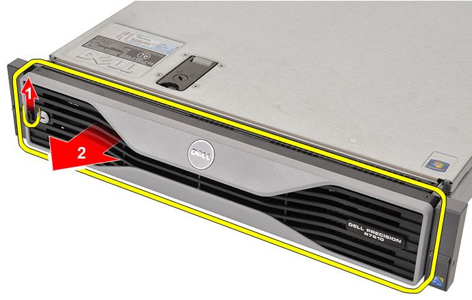
3. Complete.
| Front Bezel Reassembly Steps | |
| 1 | Insert the front bezel in its slot in a downward direction and push it towards the computer. |
| 2 | Secure the release tab. |
| 3 | Lock the front bezel using the key provided. |
5. System Cover Removal
1. Establishing image.
2. Rotate the latch release lock counter clockwise to the unlocked position.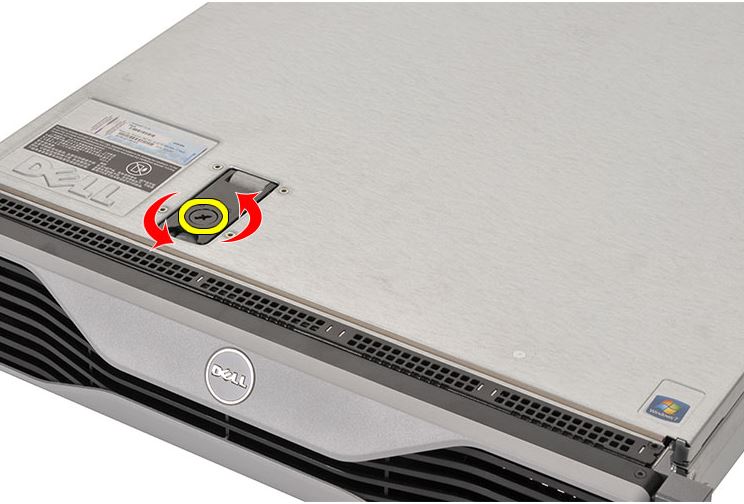
3. Lift the latch and slide the cover toward the back of the system.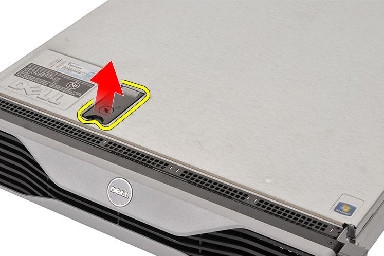
4. Grasp the cover on both sides and lift the cover away from the system.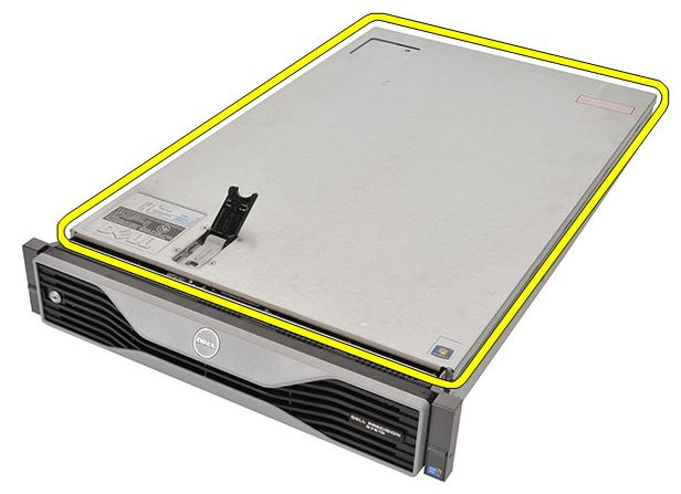
5. Complete.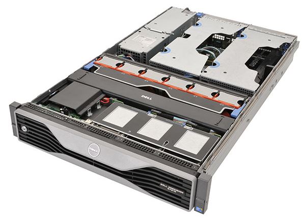
| System Cover Reassembly Steps | |
| 1 | Place the cover on the computer and press it down until it clicks into place. |
| 2 | Press down the cover latch. |
Affected Products
Precision R7610Article Properties
Article Number: 000141913
Article Type: Solution
Last Modified: 21 Feb 2021
Version: 3
Find answers to your questions from other Dell users
Support Services
Check if your device is covered by Support Services.