


This post is more than 5 years old
10 Posts
0
615409
Jumper pin position on a Dell MIH61R MB (Inspiron 620)
Hello and help!
I bought my wife a Dell Inspiron 620 new. I was de-dusting the inside and knocked off a jumper pin connector. It is a five(5) pin labeled PWRSW1 located at the outside edge near the end of the DIMMs. The MB is a MIH61R. Can anyone tell me the proper position for the jumper on PWRSW1??
Thx
RoHe
10 Elder
10 Elder
•
43.8K Posts
0
April 5th, 2015 15:00
Let's back up a nano-sec...
Have to ask if you're certain the jumper was actually on that 5-pin motherboard header? Could it have come off some other header?
I just pinged Dell-Chris M to see if he can get some specific info for you...
tigerseye
10 Posts
0
April 5th, 2015 18:00
Hey guys...it is up and running!!!! ...thanks to Speedstep, KirkD, RoHe, rdunnill, and Chris M if he got involved. You guys are the best!! Thanks for sticking with it!!
And my wife thanks you too!
With humble regards.
Tigerseye.
speedstep
9 Legend
9 Legend
•
47K Posts
0
April 3rd, 2015 06:00
There are 10 pin and more but never 5 pin connectors. The power from the front panel connection is circled. Its keyed so it should not be hard to put on.
kirkd
5.2K Posts
0
April 3rd, 2015 08:00
In SpeedSteps picture of the system board look for a two-row 5 pin (2 in one row and 3 in the second) connector just to the right of the memory modules, under the bundle of wires near the top edge.
speedstep
9 Legend
9 Legend
•
47K Posts
0
April 3rd, 2015 09:00
I put a circle around where it goes.
tigerseye
10 Posts
0
April 3rd, 2015 11:00
Thanks KirkD and Speedsteps for your reply.
The resolution of the pictures is excellent but this is not the jumper pin area I am speaking about.
Since my original description was apparently not clear, I have attached some (4) pictures to clarify the area in question. I too circled the area near the end of the dimms.
Thanks
RoHe
10 Elder
10 Elder
•
43.8K Posts
0
April 3rd, 2015 14:00
Don't see your pix, but I checked the manual and the 5 pin connector is in the corner where you indicated.
Unfortunately, it's not identified in the legend so no way for me to know what it does or how to set the jumper.
tigerseye
10 Posts
0
April 3rd, 2015 15:00
Hi RoHe.
Thanks for the response. You have correctly identified the pin location. And as you indicated, they fail to show the position the jumper connector should be in. I have spent hours dancing around the internet looking for photos of the mb, schematics of the mb and wiring diagrams to see the jumper position.
The super clear picture that was sent earlier would have shown me what I wanted to know...if it weren't for the wire bundle covering it.
I have learned there are file size limits for this site. All but one of mine were over the limit so I'll try again.
Thanks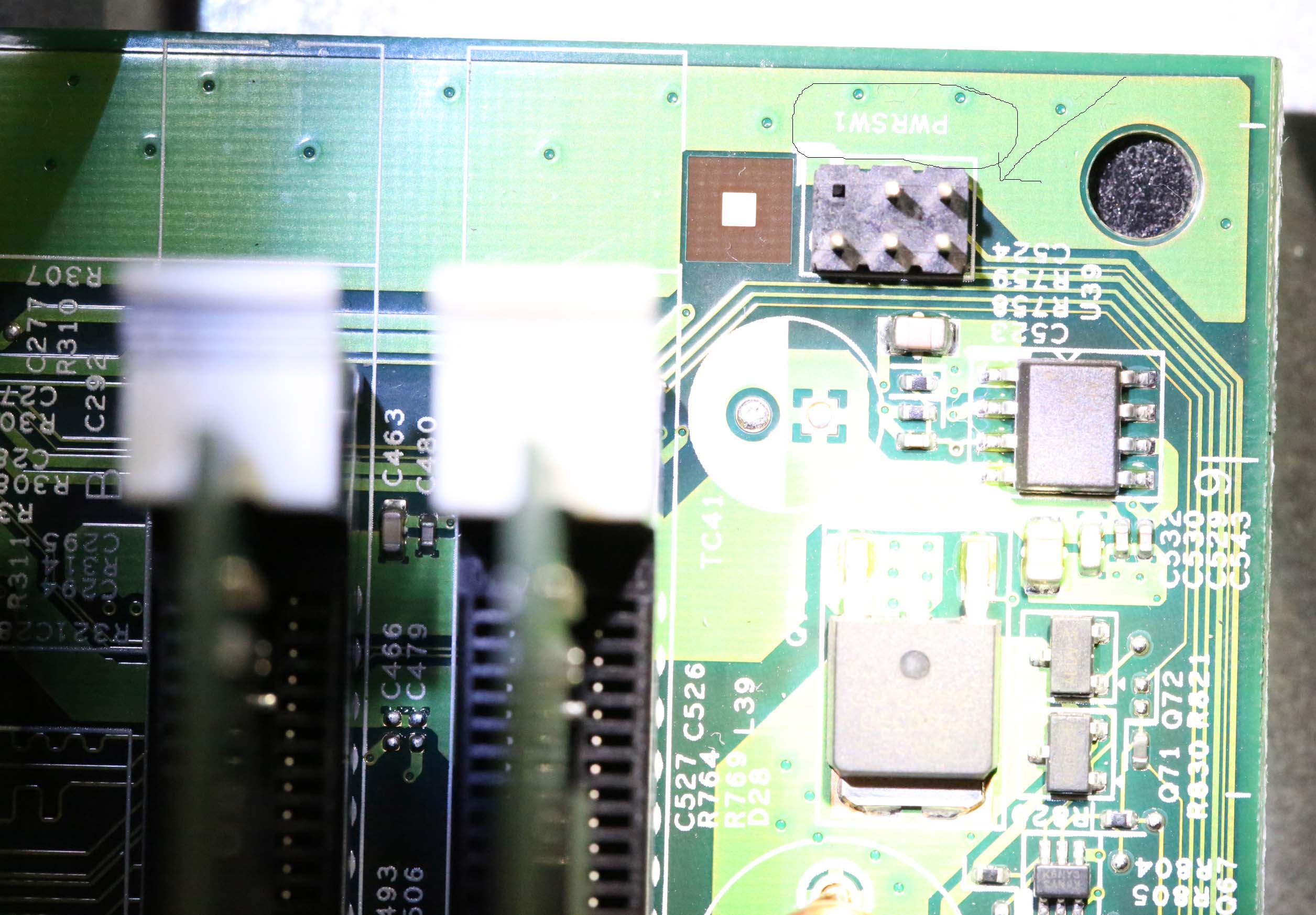
RoHe
10 Elder
10 Elder
•
43.8K Posts
0
April 3rd, 2015 18:00
Since it appears to be related to power (pwrsw1), make certain you confirm that the voltage of the system you use as the reference standard for reinstalling the jumper matches the voltage of your own system.
Eg, are you in USA with a 115V system or in the EU (or elsewhere) with a 230 V system? We don't want the thing to go up in puff of smoke.
And next time, don't be such a clean freak. Just use canned air to chase away the bust bunnies. :emotion-4:
BTW: You can always make pix small(er) in your posts because double-clicking them will open a larger version that's easier to see.
tigerseye
10 Posts
0
April 3rd, 2015 19:00
Thanks for that tip on the voltage and the pics . :p I am in the States so at the 115V level. I will use my volt/ohm meter to read the pins but wondering if there will be multiple hot pins in that group.
I will continue the quest...thx for ur help.
I like ur icon. I have petted both the Giant and Red Pandas in Chengdu China while I was living there.
ciao
tigerseye
10 Posts
0
April 3rd, 2015 20:00
RoHe, that would be excellent if Speedstep or anyone could post a picture with good enough resolution for me to see that jumper installed.
I avoided the word avatar because it's my understanding that an avatar is suppose to look something like a person looks or wants to look. I have little doubt that you have no interest in looking like a panda. ;)
Later...
RoHe
10 Elder
10 Elder
•
43.8K Posts
0
April 3rd, 2015 20:00
Hopefully, Speedstep can post a picture where you can actually see the jumper.
(My avatar was cropped from a photo I took of a panda at the San Diego zoo.)
speedstep
9 Legend
9 Legend
•
47K Posts
1
April 4th, 2015 22:00
ChrisM would be the person to ask. My 620 has no such jumper.
The ONLY jumpers on the board are in a different place.
Remove the 2 pin jumper plug from pins 1 and 2 and
replace it on pins 2 and 3 to enable the password feature.
The 5 pins by the ram slots have NOTHING on them.
tigerseye
10 Posts
0
April 5th, 2015 07:00
Hey Speedstep...thanks for the reply. The PSWDCLR1 is on the wrong end of the board. That schematic show it just above and slightly to the right of the DIMMs.
I have attached some new pictures to clarify the motherboard, the pin location (circled) and closeups. I hope they help.
This is a Stateside Dell, though I am not sure if that makes any difference in this case.
Thx!!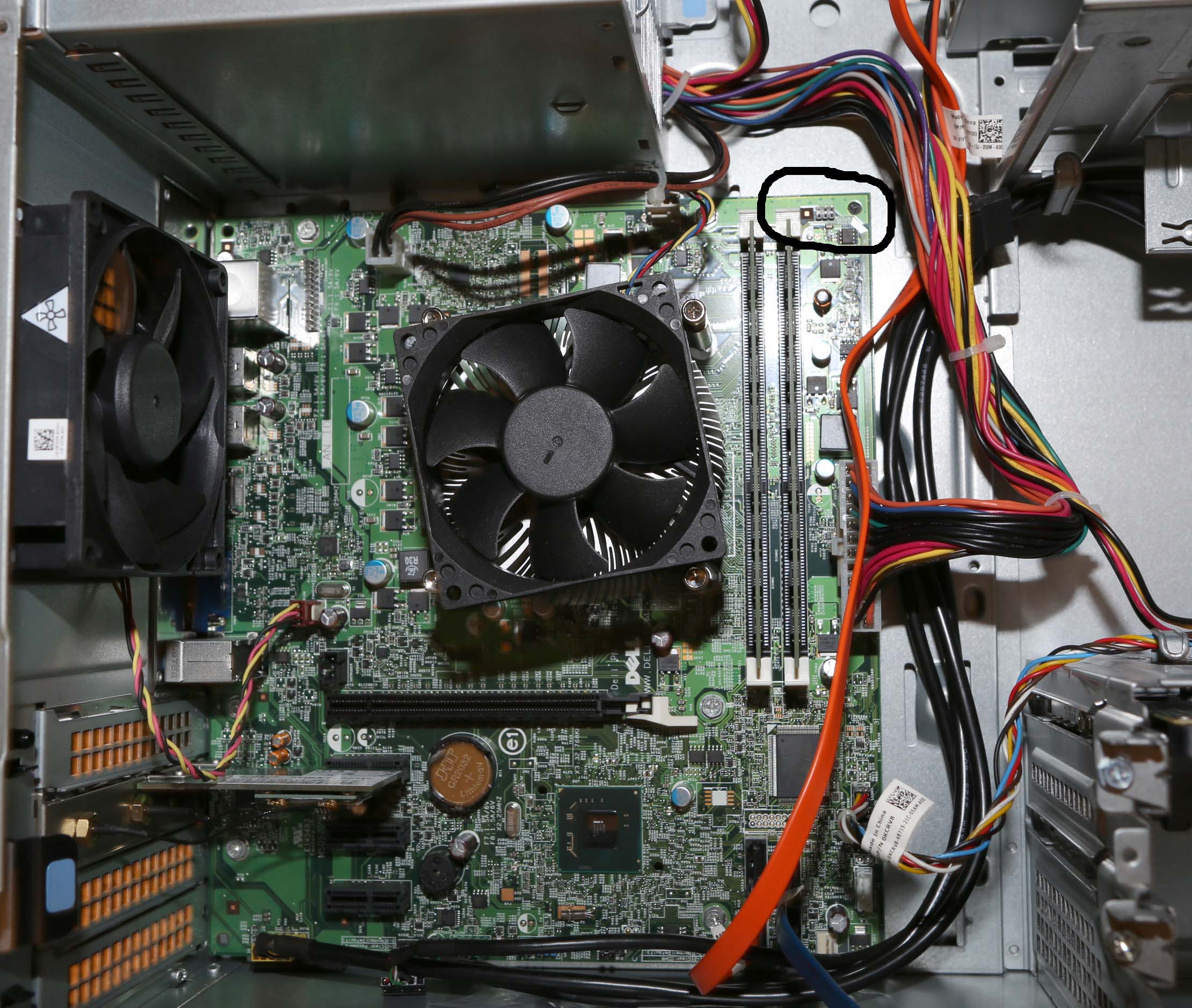

rdunnill
6 Professor
6 Professor
•
8.8K Posts
0
April 5th, 2015 11:00
This board is shared with the OptiPlex 390, which uses this header to connect a proprietary power switch/LED assembly.
None of the photos of MIH61R motherboards on eBay have any pins on this header block jumpered. It might be that you can leave it so.