How to Stack Dell PowerConnect 62XX Switches
Summary: The goal of this Knowledge Base article is to provide instruction on how to stack Dell PowerConnect 62XX switches.
Symptoms
Table of Contents
1. Introduction2. Stacking capabilities of 62XX switches
3. How to configure stacking on 62XX switches
4. Points to remember
Introduction
Stacking is used to reduce the points of administration for switches. Multiple switches when stacked together will act as a single unit and can be managed via single IP address and single console session. This document will walk through the stacking feature set present on the PowerConnect 62XX series. The series includes the PowerConnect 6224, PowerConnect 6224P, PowerConnect 6224F, PowerConnect 6248 and PowerConnect 6248P.
Stacking Capabilities of Dell PowerConnect 62XX switches
Dell PowerConnect 62XX supports up to 12 units per stack. Stacking can be done only via expansion modules, Front-Panel port stacking is not supported. Expansion modules can be installed in Bay 1 and Bay 2 present at the rear side of the switch.
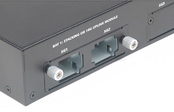
Figure 1: Stacking module installed on Bay-1
Dell 3-Meter or 1-Meter stacking cable should be used to connect between the stacking modules on the different switches.
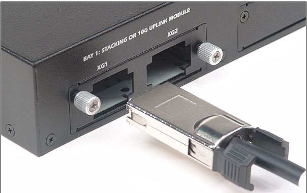
Figure 2: Dell Stacking Cable
How to configure stacking on 62XX switches
After connecting the stacking modules and the stacking cables to the switches the PowerConnect 62XX should be configured to operate the stacking ports in stack mode. By default the stacking ports will run in Ethernet mode and will not form a stack until configured to operate in stack mode. It is recommended to connect the stacking cables in a cross cabled also known as ring fashion.
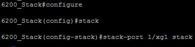
Figure 3: Configuring Stack mode
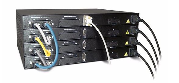
Figure 4: Cross-Cable Connection
The stack mode on the ports should be configured on all the switches involved in stack. The operation mode of a port can be determined using the command "show stack-port".
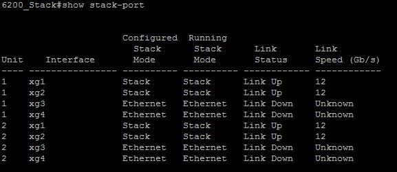
Figure 5: Output of show stack-port
The firmware on the switches which are to be stacked should be in the same version, switches with different firmware version will not form a stack. The firmware of the switches can be verified using the "show switch" command.
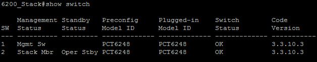
Figure 6: Output of show switch
The switch with "Oper Stby" output in the standby status on the show switch output is the standby switch of the stack. This can be verified using the "show stack-standby" command as well.
The consolidation of the steps to successfully configure a PC62XX stack are
- Connect the expansion modules to the switches
- Connect the stacking cables
- Configure the ports to operate in stack mode
- Reboot the Primary switch
- Reboot the Standby switch
- Reboot the Secondary switches
Points to remember
- Software version should be same on both the switches
- If a software upgrade is performed after formation of stack, the primary switch will automatically distribute the new code to the secondary switches.
- PC62XX cannot be stacked with other switch models
- The switch which has the highest uptime or lowest MAC address is elected as the primary
- The front panel lights indicate the primary status of the switch. If the primary LED is lit, it indicates that the switch is acting as the primary of the stack. The unit LED light indicates the unit number of the switch.
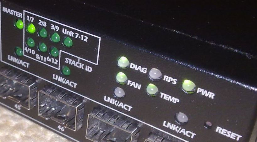
Figure 7: Primary and Unit LED's on the front panel of the switch