Precision 7530 Teardown Removal Guide for Customer Replaceable Parts (CRUs)
Summary: This article is a guide to the parts of the Dell Precision 7530 Mobile Workstation that are considered OK for anyone to remove and replace.
Symptoms
These guides take you step by step through the safe removal of the customer replaceable unit (CRU) parts of a Precision 7530 Mobile Workstation. CRUs are the parts of the computer that should not need an engineer to remove or replace. The guides also include figures to reference what is involved.
Cause
Not applicable
Resolution
Table of Contents:
Removal Guide
If these guides do not cover what you are looking to do, then reference your System Manual.
The article below provides information about safe practices to consider before working with electrical equipment.
Removal Instructions
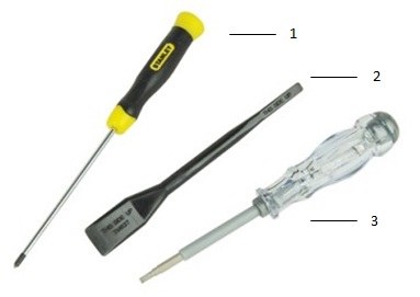
| 1 | Small Phillips head screwdriver | 2 | Plastic scribe |
| 3 | Small flat head screwdriver |
-
Pre-removal instructions before removing the main access panel:
-
During installation or removal of any hardware, always ensure that all data is backed up properly.
-
Disconnect any telephone, network, or USB cables from the computer.
-
Disconnect the computer and all attached devices from their electrical outlets.
-
-
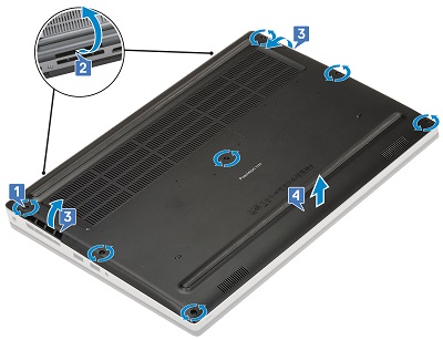
Loosen the seven captive screws that secure the cover to the chassis [1].
-
Using a plastic scribe or similar tool, pry the base cover up from the top edge of the computer [2] and then continue around the cover [3] to release it from the chassis.
-
Lift the cover up and off the chassis [4].
-
Pre-removal instructions before removing the battery:
-
During installation or removal of any hardware, always ensure that all data is backed up properly.
-
Disconnect any telephone, network, or USB cables from the computer.
-
Disconnect the computer and all attached devices from their electrical outlets.
-
Remove the System Cover.
-
-
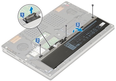
To remove the 6-Cell battery, disconnect the cable from the motherboard and remove the cable from the routing channel[1]. Remove the three screws holding the battery to the chassis [2]. Remove the battery from the computer [3].
-
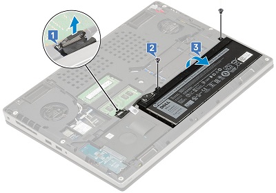
To Remove the 4-Cell battery, disconnect the cable from the motherboard [1], remove the two screws that secure the battery to the chassis [2] and remove the battery from the chassis [3].
-
Pre-removal instructions before removing the keyboard trim:
-
During installation or removal of any hardware, always ensure that all data is backed up properly.
-
Disconnect any telephone, network, or USB cables from the computer.
-
Disconnect the computer and all attached devices from their electrical outlets.
-
Remove the System Cover and Battery.
-
-
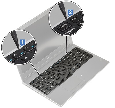
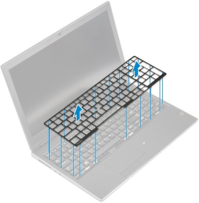
Using a plastic scribe or similar tool, pry up the trim starting at the recess points along the top edge [1] and [2], and continue around the trim going in a clockwise direction.
-
Lift the trim up to remove it from the computer.
-
Pre-removal instructions before removing the keyboard:
-
During installation or removal of any hardware, always ensure that all data is backed up properly.
-
Disconnect any telephone, network, or USB cables from the computer.
-
Disconnect the computer and all attached devices from their electrical outlets.
-
Remove the System Cover, Battery, and Keyboard Trim.
-
-
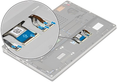
With the computer on its lid, lift the latch and disconnect the keyboard cable, the fingerprint cable and the fingerprint button cable from the connector.
-
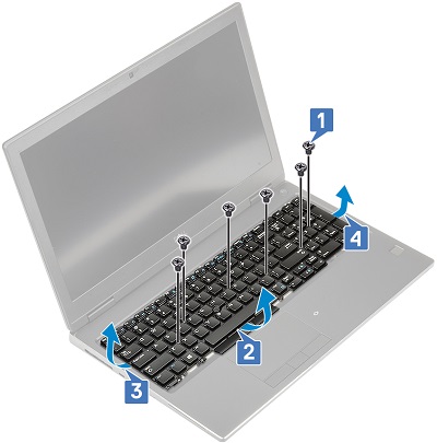
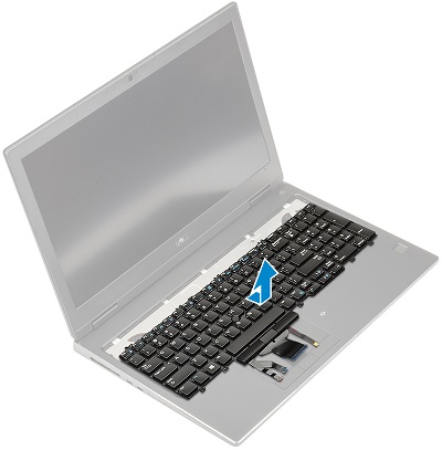
Turn the computer back onto its base and open the computer up. Remove the six screws that secure the keyboard to the chassis [1] and then pry the bottom edge of the keyboard and the left and right sides [2, 3, 4].
-
Slide the keyboard towards the palm rest and lift up and out of the computer.
-
Pre-removal instructions before removing the memory:
-
During installation or removal of any hardware, always ensure that all data is backed up properly.
-
Disconnect any telephone, network, or USB cables from the computer.
-
Disconnect the computer and all attached devices from their electrical outlets.
-
Remove the System Cover and Battery.
-
-
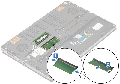
Pull the metal clips on the short sides of the memory DIMM apart, until the module pops up at an angle to the connector [1].
-
Lift the memory DIMM out of the computer [2].
-
Pre-removal instructions before removing the hard drive:
-
During installation or removal of any hardware, always ensure that all data is backed up properly.
-
Disconnect any telephone, network, or USB cables from the computer.
-
Disconnect the computer and all attached devices from their electrical outlets.
-
Remove the System Cover and Battery.
-
-
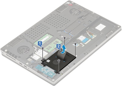
You must remove the four screws from each corner [1] of the hard drive and then push the hard drive to the center of the chassis and lift it up and away from the computer [2].
-
Pre-removal instructions before removing the solid-state drive (SSD):
-
During installation or removal of any hardware, always ensure that all data is backed up properly.
-
Disconnect any telephone, network, or USB cables from the computer.
-
Disconnect the computer and all attached devices from their electrical outlets.
-
Remove the System Cover and Battery.
-
-
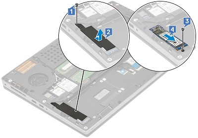
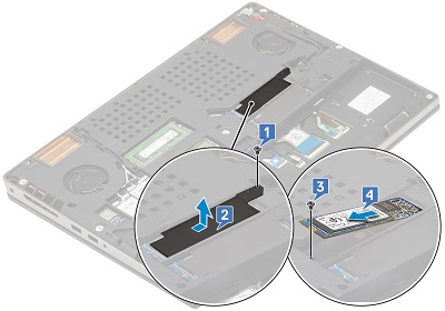
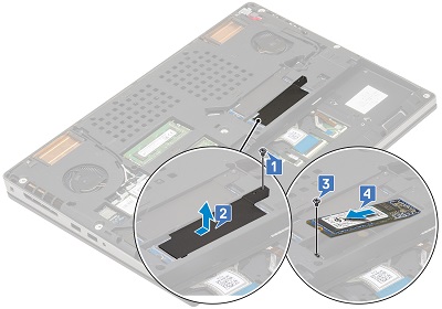
Remove the screw that secures the end of the thermal plate to the motherboard [1], slide off the thermal plate [2] and remove the single screw that secures the M.2 SSD to the motherboard [3]. Lift the card to a 45-degree angle and remove from the connector [4].
-
Pre-removal instructions before removing the SD card:
-
During installation or removal of any hardware, always ensure that all data is backed up properly.
-
Disconnect any telephone, network, or USB cables from the computer.
-
Disconnect the computer and all attached devices from their electrical outlets.
-
-
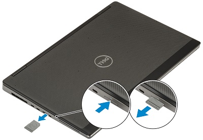
Push the SD card further into the machine and release. Once it pops out the side of the computer, grip it and pull it the rest of the way out of the machine.
If you require further assistance, contact Technical Support.
| Contact Us |