OptiPlex 3080 Small Form Factor Teardown Removal Guide for Customer Replaceable Unit
Summary: This article is a guide to safe removal and replacement of those parts of a OptiPlex 3080 Small Form Factor (SFF) that Dell considers safe and simple for anyone to attempt.
This article applies to
This article does not apply to
This article is not tied to any specific product.
Not all product versions are identified in this article.
Instructions
These guides take you step by step through the safe removal of what are considered to be the Customer Replaceable Unit (CRU) parts of the OptiPlex 3080 Small Form Factor (SFF). (CRU is the part of the system that should not need an engineer to remove or replace.) The guide includes images referencing what is involved.
Table of Contents:
If this guide does not cover what you are looking to do, then refer to the System Manual.
The article below provides information about safe practices that you should consider before working with electrical equipment.
NOTE: Click the title of the section that you want to open below, in order to see the contents.
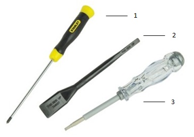
| 1 | Small Phillip's head screwdriver | 2 | Plastic Scribe |
| 3 | Small Flat head screwdriver |
NOTE: Using a large Phillips or Flat Head screwdriver may result in damage to the head of the screws. This would make their removal impossible without specialty tools that are not available to our onsite engineers.
-
Pre-Removal instructions before removing the System Cover:
-
During installation or removals of any hardware always ensure that all data is backed up properly.
-
Disconnect any telephone, network, or USB cables from the computer.
-
Disconnect the computer and all attached devices from their electrical outlets.
-
-
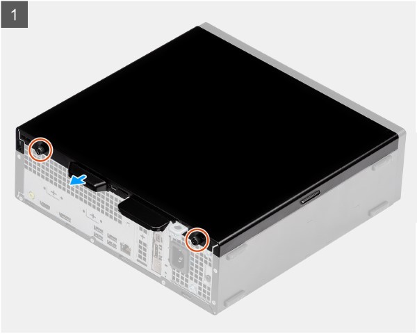
Put the system on its side with the access panel facing up, and loosen the two (2) captive screws on the back of the system [1].
-
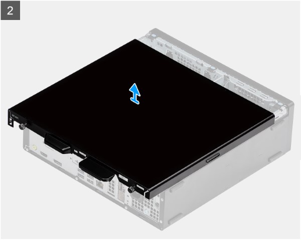
Slide the access panel towards the rear of the computer and lift the cover away from the computer.
-
Pre-Removal instructions before removing the Front Bezel:
-
During installation or removals of any hardware always ensure that all data is backed up properly.
-
Disconnect any telephone, network, or USB cables from the computer.
-
Disconnect the computer and all attached devices from their electrical outlets.
-
Remove the System Cover.
-
-
Establishing an image.
-
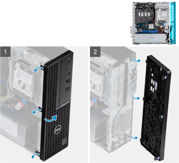
Pry the retention tabs [1] to release the front bezel from the computer.
-
Pull the front bezel slightly and then gently rotate [2] to release other tabs.
-
Remove the front bezel from the computer.
-
Pre-Removal instructions before removing the Heat-sink:
-
During installation or removals of any hardware always ensure that all data is backed up properly.
-
Disconnect any telephone, network, or USB cables from the computer.
-
Disconnect the computer and all attached devices from their electrical outlets.
-
Remove the System Cover.
-
-
Establishing an image.
-
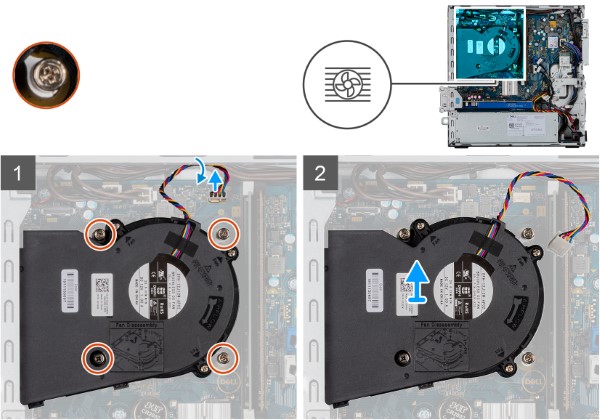
Disconnect the heat sink fan cable and loosen the four screws [1] securing the heat sink.
-
Carefully lift and remove the Heat sink from the computer.
-
Pre-Removal instructions before removing the 2.5-inch Hard Disk Drive:
-
During installation or removals of any hardware always ensure that all data is backed up properly.
-
Disconnect any telephone, network, or USB cables from the computer.
-
Disconnect the computer and all attached devices from their electrical outlets.
-
Remove the System Cover and Heat-sink.
-
- Remove Hard Drive Assembly:
-
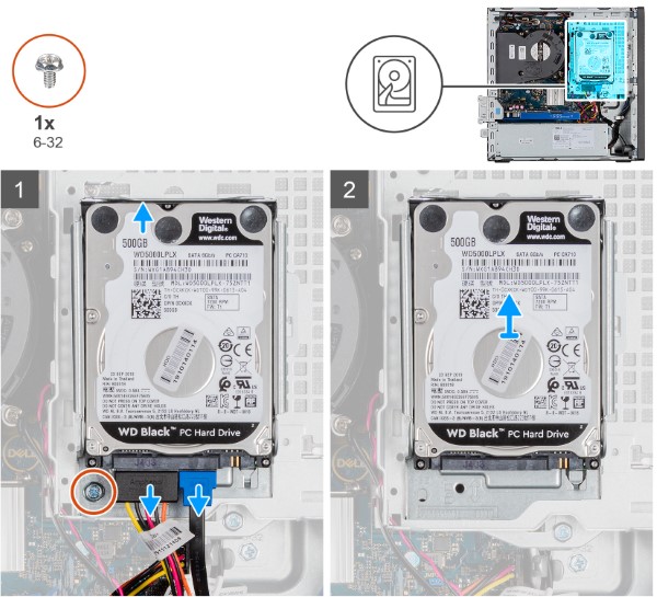
Disconnect the hard drive data and power cables [1] from the connectors on the 2.5-inch hard drive.
-
Remove the screw and release the notch above the hard drive Assembly.
-
Lift the hard drive assembly [2] from the computer.
-
- Remove Hard Drive bracket:
-
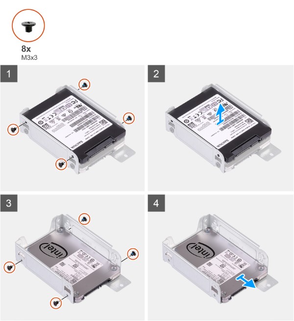
Remove the eight (M3x3.5) screws that secure the hard drive to the hard drive metal bracket.
-
Slide and lift the hard drive from the hard drive metal bracket.
-
-
Pre-Removal instructions before removing the M.2 2230 PCIe solid state drive (SSD):
-
During installation or removals of any hardware always ensure that all data is backed up properly.
-
Disconnect any telephone, network, or USB cables from the computer.
-
Disconnect the computer and all attached devices from their electrical outlets.
-
Remove the System Cover and Hard Drive assembly.
-
-
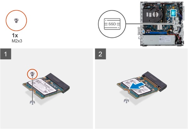
Remove the screw (M2x3.5) that secures the solid state drive to the system board.
-
Slide and lift the solid state drive off the system board.
-
Pre-Removal instructions before removing the Memory:
-
During installation or removals of any hardware always ensure that all data is backed up properly.
-
Disconnect any telephone, network, or USB cables from the computer.
-
Disconnect the computer and all attached devices from their electrical outlets.
-
Remove the System Cover and Hard Drive assembly.
-
-
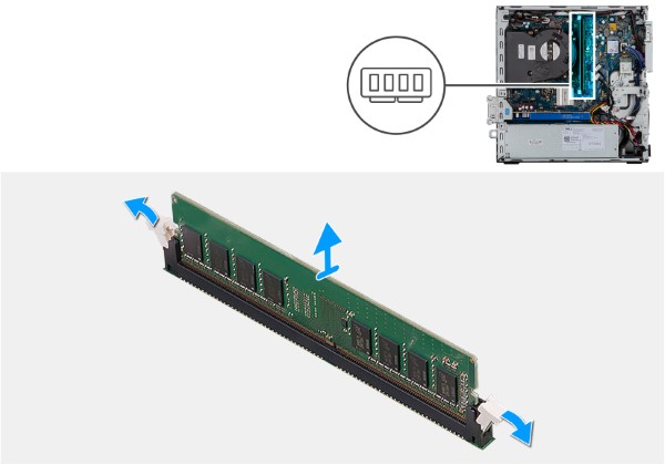
Establishing an image.
-
Pull the securing clips from both sides of the memory module until the memory module message display appears.
-
Slide and remove the memory module from the memory-module slot.
NOTE: Repeat Steps 3 and 4 for any additional Memory DIMMs located in the system.
-
Pre-Removal instructions before removing the Coin Cell Battery:
-
During installation or removals of any hardware always ensure that all data is backed up properly.
-
Disconnect any telephone, network, or USB cables from the computer.
-
Disconnect the computer and all attached devices from their electrical outlets.
-
Remove the System Cover.
-
-
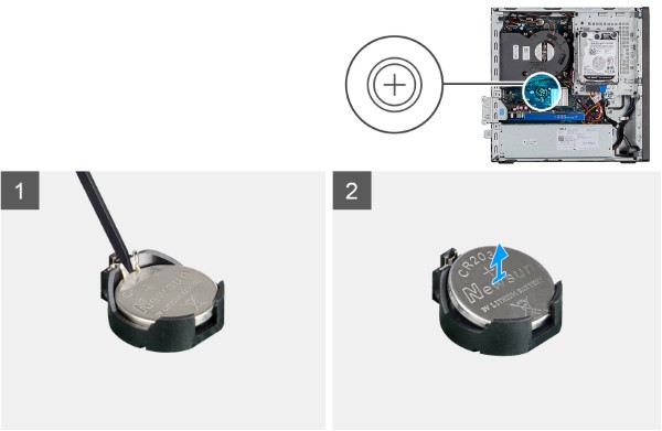
Establishing an image.
-
Using a plastic scribe, gently pry the coin-cell battery out of the slot on the system board.
-
Remove the coin-cell battery away from the computer.
-
Pre-Removal instructions before removing the Optical Disc Drive:
-
During installation or removals of any hardware always ensure that all data is backed up properly.
-
Disconnect any telephone, network, or USB cables from the computer.
-
Disconnect the computer and all attached devices from their electrical outlets.
-
Remove the System Cover.
-
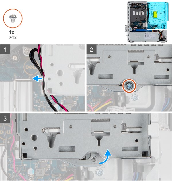
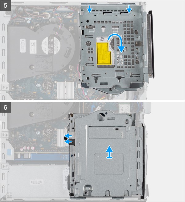
- Remove Optical Disc Drive Assembly:
-
Unroute the Hard Drive and ODD cables from the retention clip [1].
-
Loosen and remove the screw (6-32) securing the cage.
-
Tilt to release tabs of the drive cage and lift the cage away from the chassis.
-
Affected Products
OptiPlex 3080 Small Form FactorArticle Properties
Article Number: 000180605
Article Type: How To
Last Modified: 05 Feb 2026
Version: 11
Find answers to your questions from other Dell users
Support Services
Check if your device is covered by Support Services.