PowerFlex Manager: Network settings for deploying new or existing service
Summary: PowerFlex Manager supports adding nodes to existing services or deploying them into new services. This article will provide guidance to ensure the network settings are correct to allow for successful deployment. For new services, the network settings can be adjusted in the template to match the NIC configuration on the new nodes. When adding nodes to an existing service, it is recommended to have the same NIC layout and settings across all nodes, but if that is not the case, this article will provide guidance on how to successfully deploy the nodes as desired. ...
This article applies to
This article does not apply to
This article is not tied to any specific product.
Not all product versions are identified in this article.
Instructions
PowerFlex Manager requires two switches to form the backbone for the PowerFlex traffic with supported NICs on the nodes in a PowerFlex Rack or PowerFlex Appliance system to achieve optimal performance, high availability, and ease of expansion.
Note: In this article, we use the wording like "remove a service" or remove items from PowerFlex Manager in a few procedures, please understand those procedures are non-disruptive to the production environment.
PowerFlex Manager supports two types of network deployment:
Full network automation (FNA): This type of deployment used in a Rack-based setup where complete end-to-end network configuration is automated and done by PowerFlex Manager. The only configuration that is required to config the uplink connectivity to the customer core network. Only certain models of Dell & Cisco switches are supported.
Partial network automation (PNA): This type of deployment is typically used when customers want to use their own switches or do not want PowerFlex Manager to mange the switches. This is only supported for PowerFlex Appliance deployments. In this case, the customer must configured the switches per our network requirements. This is more prone to errors as features such as error handling, network monitoring, and network automation cannot be achieved. Refer to below KB for more details about PNA Requirements: https://www.dell.com/support/kbdoc/en-us/000188309
Deployment of new node(s) in an existing service:
PowerFlex Manager supports various models of nodes to be a deployed to new or existing services. When a new node is to be deployed in an existing service, PowerFlex Manager duplicates the existing service template settings to deploy the nodes with the same network settings such as NIC speed and VLAN definition. Deployment may fail if there is a difference in network card configurations between the new and existing nodes. This is because of how PowerFlex Manager chooses the NICs. It selects the first NIC, in slot order, that meets the requirements (ports and NIC speed) defined in the service template settings and starts the deployment of the node(s). If the cabling is different in the new node(s), PowerFlex Manager may not have the correct connectivity and the deployment of the node will fail.
The first step to deploy these new nodes is to verify the network settings used in the service.
- Login to PowerFlex Manager GUI and navigate to the Services pane. Then click the name of the service you want to add nodes to.
- In the Service Details pane, click the View All Settings button which will display the service settings.
- Select any node and expand it. Then expand network settings and review the network settings defined in the service. This will show what interfaces are being used in terms of network interfaces, NIC speed. and VLANs assigned to each port.


Refer to the below table for reference in the example scenarios.
| Model | Node Type | Slot 1 | Slot 2 | Slot 3 | Slot 4 | Slot 5 |
| 14G | A1 | Integrated Intel 10G/1G | Mellanox 25G | Mellanox 25G | (empty) | (empty) |
| 14G | A2 | Mellanox 25G | Mellanox 25G | Mellanox 25G | (empty) | (empty) |
| 15G | B1 | Mellanox 25G | (empty) | (empty) | Mellanox 25G | (empty) |
| 15G | B2 | Mellanox 25G | Mellanox 25G | Mellanox 25G | Mellanox 25G | (empty) |
Note: There is no such classification for Node type mentioned above, they are just their for understanding below examples.
Example 1: An existing service deployed using A1 nodes from the above table. The new nodes are A2 nodes and have a different NIC layout.
- In this existing Service four A1 type nodes are cabled up with Mellanox adapters in slot 2 and slot 3 and the integrated NIC is not in use. The template settings used for deployment had defined 2 - 25G NICs to be used for their network settings.
- Now to match the same port and NIC speed we have cabled the 25G NIC and connected the two new A2 type nodes with Slot 2 and Slot 3.
- When we begin the deployment to add these nodes into the existing service it will fail because PowerFlex Manager will choose the first NIC it finds that meets the requirements which would be the integrated NIC in Slot 1 and the NIC in Slot 2. Since only slot 2 and slot 3 are cabled to the switches, this deployment will fail because switch connectivity cannot be established on the NIC in Slot 1.
- There are multiple ways to ensure the deployment completes successfully with the existing service settings.
- Option 1: Change the cabling so that Slot 1 and Slot 2 are cabled to the switches and retry the deployment.
- Option 2: Disable the Integrated NIC in slot 1 and then perform the deployment. Refer to this KB for instructions: https://www.dell.com/support/kbdoc/en-us/000196618
Example 2: An existing service is deployed with four B1 nodes from the above table. The new nodes are B2 nodes from the above table, but we want to use Slot 2 and Slot 4 for the standard networks for our PowerFlex system. The other NICs will be used by the customer for other types of traffic
- If these nodes were added to the existing service it would try to use NIC slot 1 and slot 2.
- Since we want to use different NICs, the best method to deploy the new nodes would be into a new service.
- The nodes can be deployed to the existing cluster in vCenter and/or PD in PowerFlex, but will just have different network settings in the template to match the NICs you have cabled.
- If nodes are deployed to a new or temporary cluster with the intention of manually moving them to the new cluster after they are deployed, additional manual steps are necessary to complete the process.
- Later, you can remove the new service from PowerFlex Manager and run an update service details on the existing service to get the new nodes to show on the existing service after deployment.
- Note: Future expansion on a service with mixed network configurations would require deploying to a new service and following these steps above to get the nodes shown in the existing service instead of a separate service.
Deployment of new nodes into a new service:
When deploying a new service, each type of service has a minimum number of nodes. When a new service needs to be deployed, it is critical that the template settings match the underlying hardware and how we have it cabled. We have seen instances where the NICs we are cabling do not necessarily match the order in which PowerFlex Manager will select them because the NICs are all the same type and speed. You can workaround this by making edits to your template before deployment to ensure the correct NICs are configured as expected.
- In PowerFlex Manager, click on the Templates pane and then select the Sample Templates tab near the top.
- This brings you to a list of templates for different types of deployments. Click to highlight the one you want and click the Clone button on the right in the gray box.
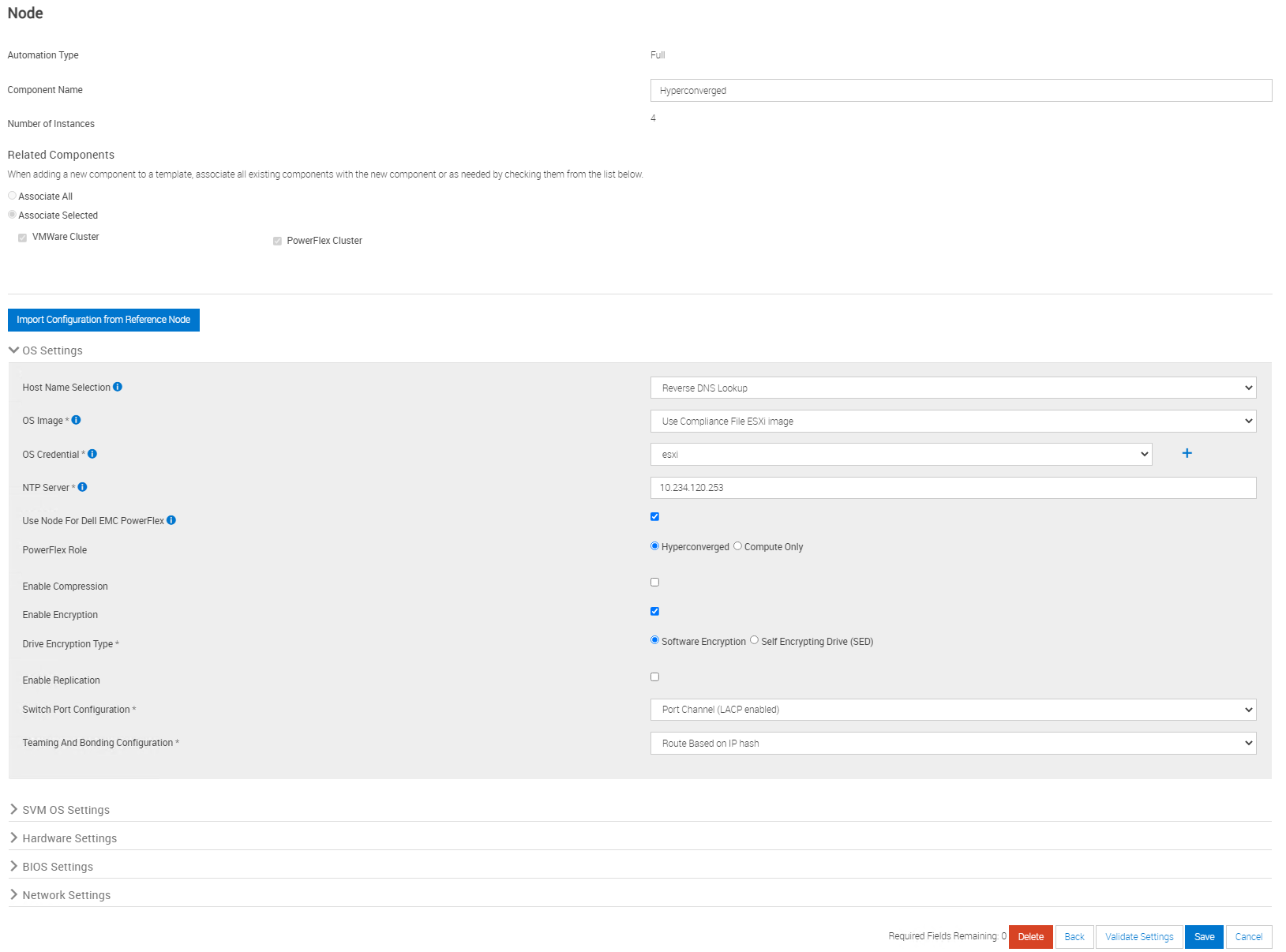
- This brings you into a wizard to define some of the settings in the template you are cloning. In this example below, I am cloning a Hyperconverged template with encryption enabled so some of the fields may be slightly different depending on the type of template being cloned.
- Define the template name, choose or create the category you want to save the template to, and make sure the firmware and software compliance is set to Use PowerFlex Manager appliance default catalog and click Next.
- On the Additional Settings screen you want to populate the fields to match the settings in your PowerFlex Manager configuration.
- Network settings: Map the required networks (all but General Purpose LAN) in the drop-downs that match the networks you have configured in Settings > Networks for each network type.
- OS Settings: Select your credentials and OS Image in the drop-downs.
- Cluster Settings: Select your vCenter where the nodes will be deployed to.
- PowerFlex Gateway Settings: Select your PowerFlex Gateway and your CloudLink Center in the drop-downs.
- Node Pool Settings: If your nodes are in a pool, choose the correct one from the drop-down. If they are not in pool leave it set to Global.
- Click Finish.
- Once the template has been cloned, you are brought to the template details screen for that template.
- Click on the node icon and click Edit.

- This opens the node template settings. Click Continue on the first screen and then scroll to bottom of the screen and expand Network Settings.
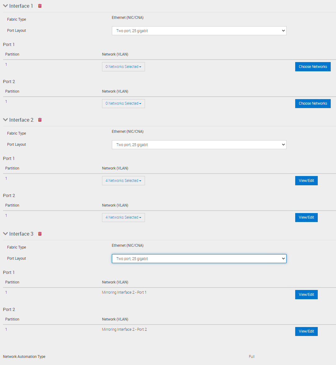
- By default, PowerFlex Manager will have two interfaces. Click on Add Interface button to add one more.
- Next you have to modify the networks to be on the correct ports. The first NIC listed is the one we want to skip so we have to remove all networks from both ports on that Interface.
- We then add the networks per the guidelines defined in this KB https://www.dell.com/support/kbdoc/en-us/000188307 to determine how to modify template settings per node type and network design. Our latest networking design is LACP bonding NIC port. Check what networking design is being used on your existing nodes before choosing which network design to use in your new node template. The configuration below will skip the first NIC and use the 2nd and 3rd 25G NICs that it finds in slot order on the system. This is our desired network configuration for this node deployment.
- Once the network settings are configured, click on the Validate Settings button at the bottom of the screen to validate that these settings match the nodes you want to deploy to.
- If it is not showing the nodes as valid, double-check your settings. Once the validation succeeds, click Save to save the changes to your template.
- You can now deploy the template which will configured the nodes into a new service.
- Note: When deploying a new service a minimum number of nodes are required for different service types. For Hyperconvered and Storage Only services, a minimum of 4 nodes are required. For Compute only services, a minimum of 3 nodes is required.
There can be many possibilities where the same models have different NIC configurations. For most of the cases, 14G and above models now have 25G NICs installed both in Integrated and PCIe slots.
Nodes could be ordered with many different NIC configurations.
- HCI, SO and CO-based service using 15G nodes Refer to link: PowerFlex appliance R650/R750/R6525 layout and matrix
- HCI, SO and CO-based service using 14G nodes Refer to link: PowerFlex appliance R640/R740xd/R840 layout and matrix
Affected Products
PowerFlex rack, ScaleIOArticle Properties
Article Number: 000200805
Article Type: How To
Last Modified: 24 Mar 2025
Version: 2
Find answers to your questions from other Dell users
Support Services
Check if your device is covered by Support Services.