Article Number: 000145439
OptiPlex 3030 All in One (AIO) Teardown Removal Guide for Customer Replaceable Units (CRUs)
Summary: These guides take you step by step through the safe removal of the customer replaceable unit (CRU) parts of an OptiPlex 3030 All in One (AIO) computer.
Article Content
Symptoms
CRUs are the parts of the computer that should not need an engineer to remove or replace. The guides include figures to reference what is involved. To add a part, reverse the removal steps.
Table of Contents:
Removal Guide
If these guides do not cover what you are looking to do, reference your System Manual.
The article below provides information about safe practices to consider before working with electrical equipment.
Cause
Not applicable
Resolution
Removal Instructions
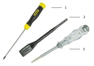
| 1 | Small Phillips head screwdriver | 2 | Plastic Scribe |
| 3 | Small Flat head screwdriver |
-
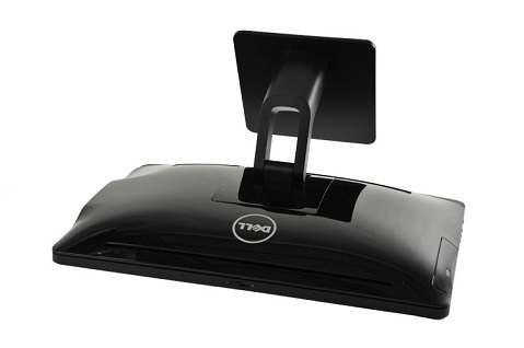
Pre-removal instructions before removing the stand cover:
-
During installation or removal of any hardware, always ensure that all data is backed up properly.
-
Disconnect any telephone, network, or USB cables from the computer.
-
Disconnect the computer and all attached devices from their electrical outlets.
-
-
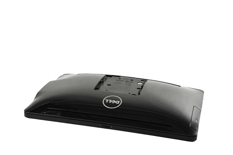
Establishing image.
-
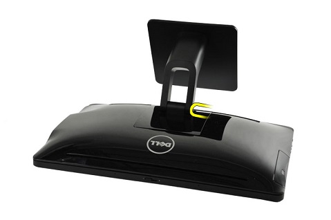
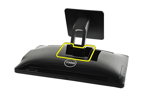
Use a plastic scribe to release the stand cover from the back of the stand.
-
Remove the stand cover from the chassis.
-
Complete.
-
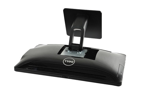
Pre-removal instructions before removing the stand:
-
During installation or removal of any hardware, always ensure that all data is backed up properly.
-
Disconnect any telephone, network, or USB cables from the computer.
-
Disconnect the computer and all attached devices from their electrical outlets.
-
Remove the Stand Cover.
-
-
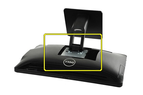
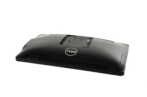
Establishing image.
-
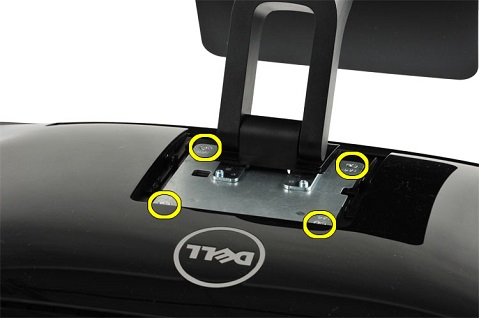
Remove the four screws from the back of the stand.
-
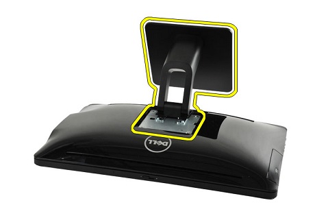
Lift the stand up and away from the chassis.
-
Complete.
-
Pre-removal instructions before removing the rear cover:
-
During installation or removal of any hardware, always ensure that all data is backed up properly.
-
Disconnect any telephone, network, or USB cables from the computer.
-
Disconnect the computer and all attached devices from their electrical outlets.
-
Remove the Stand Cover and the Stand.
-
-
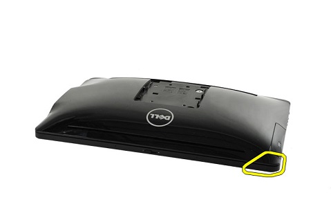
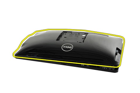
Establishing image.
-
Use a plastic scribe to unlock the tab on the upper left corner of the chassis. This is the corner by the optical drive.
-
Work your way around to loosen the rest of the tabs and remove from the chassis.
-
Complete.
-
Pre-removal instructions before removing the optical drive (CD-ROM, DVD):
-
During installation or removal of any hardware, always ensure that all data is backed up properly.
-
Disconnect any telephone, network, or USB cables from the computer.
-
Disconnect the computer and all attached devices from their electrical outlets.
-
Remove the Stand Cover, the Stand and the Back Cover.
-
-
Establishing image.
-
Remove one screw from the rear of the optical drive.
-
Use a screw driver to push the optical drive out the side of the chassis. Push against the rear of the drive.

-
Remove the optical drive from the computer.
-
Complete.
-
Pre-removal instructions before removing the hard disk drive:
-
During installation or removal of any hardware, always ensure that all data is backed up properly.
-
Disconnect any telephone, network, or USB cables from the computer.
-
Disconnect the computer and all attached devices from their electrical outlets.
-
Remove the Stand Cover, the Stand and the Back Cover.
-
-
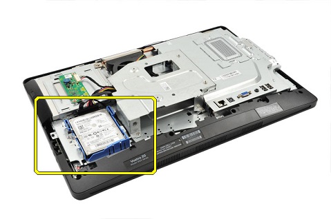
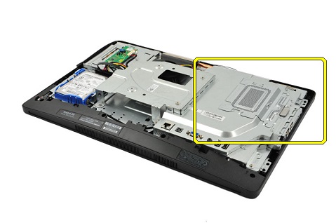
Establishing image.
-
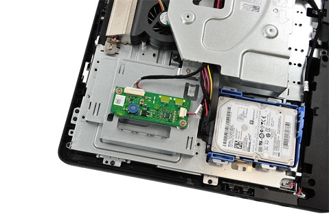
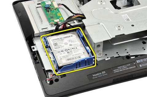
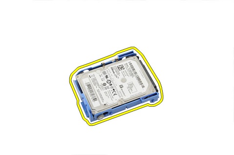
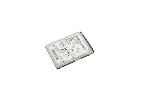
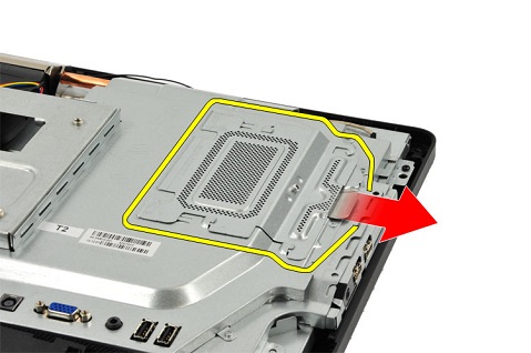
Pull the drive towards the bottom of the computer and then lift up to remove it from its securing bracket.
-
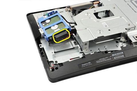
Remove the cables from the rear of the drive.
-
Peel the hard drive cage from the hard drive.
-
Complete.
-
Pre-removal instructions before removing the memory:
-
During installation or removal of any hardware, always ensure that all data is backed up properly.
-
Disconnect any telephone, network, or USB cables from the computer.
-
Disconnect the computer and all attached devices from their electrical outlets.
-
Remove the Stand Cover, the Stand and the Back Cover.
-
-
Establishing image.
-
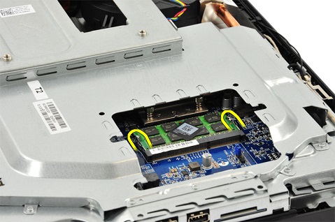
Lift up and pull forcefully on the tab to release the cover.
-
Pull apart the clips securing the memory in place, to release the memory DIMM.
-
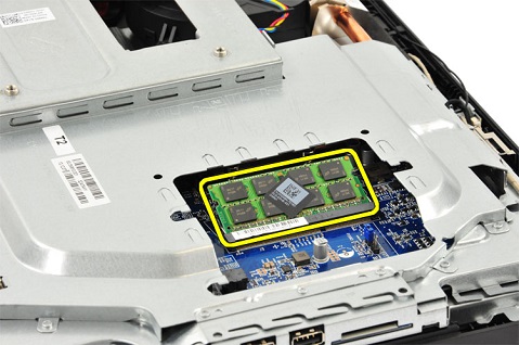
Lift the memory up and remove from the computer.
-
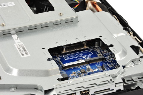
Complete.
-
Pre-removal instructions before removing the converter board:
-
During installation or removal of any hardware, always ensure that all data is backed up properly.
-
Disconnect any telephone, network, or USB cables from the computer.
-
Disconnect the computer and all attached devices from their electrical outlets.
-
Remove the Stand Cover, the Stand and the Back Cover.
-
-
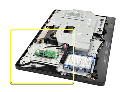
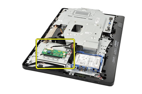
Establishing image.
-
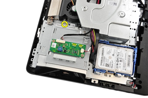
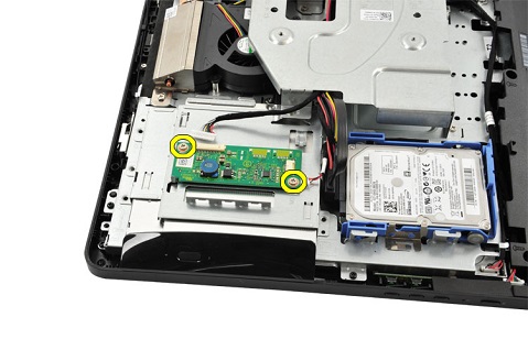
Remove the two cables from the board.

-
Remove the two screws from the board.
-
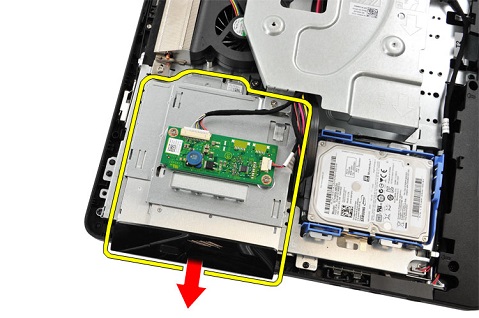
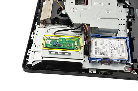
Remove the touch controller from the computer.
-
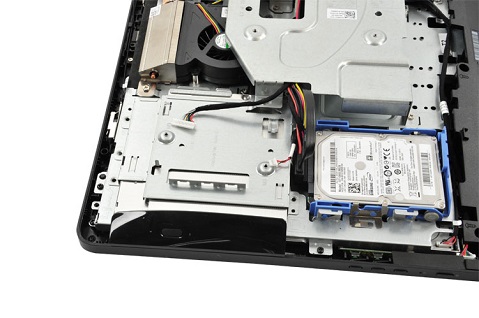
Complete.
-
Pre-removal instructions before removing the webcam:
-
During installation or removal of any hardware, always ensure that all data is backed up properly.
-
Disconnect any telephone, network, or USB cables from the computer.
-
Disconnect the computer and all attached devices from their electrical outlets.
-
Remove the Stand Cover, the Stand and the Back Cover.
-
-
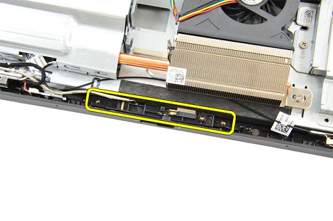
Establishing image.

-
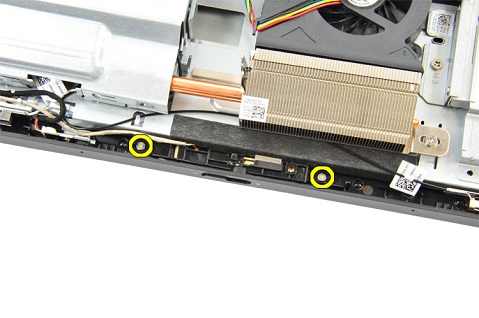
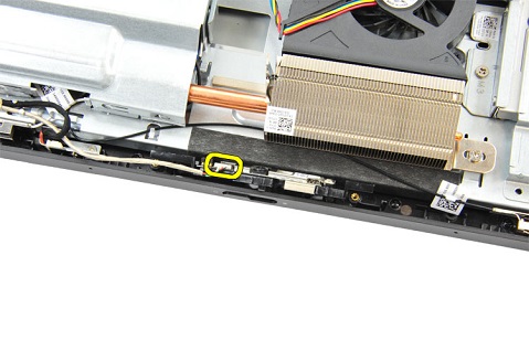
Remove two screws from the webcam.
-
Lift the webcam up and out of the chassis.
-
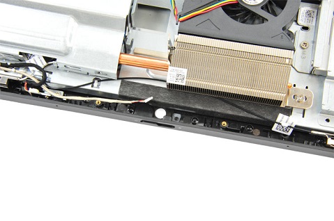
Remove the cable from the webcam.
-
Complete.
-
Pre-removal instructions before removing the microphone:
-
During installation or removal of any hardware, always ensure that all data is backed up properly.
-
Disconnect any telephone, network, or USB cables from the computer.
-
Disconnect the computer and all attached devices from their electrical outlets.
-
Remove the Stand Cover, the Stand and the Back Cover.
-
-
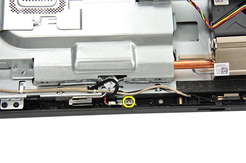
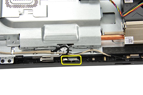
Establishing image.

-
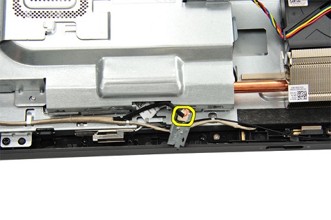
Remove the screw from the microphone card.
-
Lift the microphone up and out of the computer.
-
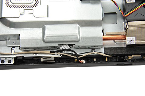
Disconnect the microphone cable from the microphone card and remove it from the computer.
-
Complete.
| If you require further assistance, contact technical Support. | ||
| Contact Us | ||
Article Properties
Affected Product
OptiPlex 3030 All-In-One
Last Published Date
05 Jul 2023
Version
5
Article Type
Solution