
Unsolved

This post is more than 5 years old

1 Rookie

 • 

45 Posts

47857

May 26th, 2012 10:00

Replacing the Motherboard on a Optiplex 745 Ultra Small Form Factor

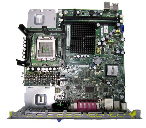
 The mother board in my Optiplex 745 ultra small form factor pc went bad, so I ordered a replacement and it just came. I had to order from spare parts so there is no instructions on how to do this. I have searched the Dell site and don't see documentation for this. For this PC the side panel with all the ports is connected to the mother board. Does anyone know of any how to videos that I could access to help me out? Also, I attached a picture of what the mobo looks like.

11 Legend

 • 

87.5K Posts

 • 

321.3K Points

May 26th, 2012 10:00

<ADMIN NOTE: Broken link has been removed from this post by Dell>

1 Rookie

 • 

45 Posts

May 26th, 2012 10:00

Here is the pic

11 Legend

 • 

47K Posts

May 26th, 2012 17:00

Removing the System Board: Mini Tower, Desktop, Small Form Factor, and Ultra-Small Form Factor Computers

  1. Before You Begin

    Dell™ OptiPlex™ 745 User's Guide

       Recommended Tools<ADMIN NOTE: Broken link has been removed from this post by Dell>

       Turning Off Your Computer <ADMIN NOTE: Broken link has been removed from this post by Dell>

     Before Working Inside Your Computer<ADMIN NOTE: Broken link has been removed from this post by Dell>


    This chapter provides procedures for removing and installing the components in your computer. Unless otherwise noted, each procedure assumes that the following conditions exist:

  2. You have performed the steps in Turning Off Your Computer<ADMIN NOTE: Broken link has been removed from this post by Dell> and Before Working Inside Your Computer<ADMIN NOTE: Broken link has been removed from this post by Dell>.

    • You have read the safety information in your Dell™ Product Information Guide.

    • A component can be replaced by performing the removal procedure in reverse order.


    Recommended Tools

    The procedures in this document may require the following tools:

    • Small flat-blade screwdriver

    • Phillips screwdriver

    • Flash BIOS update program floppy disk or CD


 NOTICE: Before touching anything inside your computer, ground yourself by touching an unpainted metal surface, such as the metal at the back of the computer. While you work, periodically touch an unpainted metal surface to dissipate any static electricity that could harm internal components.

  1. Remove any components that restrict access to the system board (optical drive(s), floppy drive, hard drive, I/O panel (as applicable).

  2. Remove the processor and heat sink assembly:

    • ultra-small form factor: see Processor 

      <ADMIN NOTE: Broken link has been removed from this post by Dell>


  3. Disconnect all cables from the system board.

  4. Remove the screws from the system board.

    • ultra-small form factor: Ultra Small Form Factor System Board Screws<ADMIN NOTE: Broken link has been removed from this post by Dell>


  5. Slide the system board assembly toward the front of the computer, and then lift the board up and away.

Back to Contents Page

Dell™ OptiPlex™ 745 User's Guide

   Removing the Computer Cover


Removing the Computer Cover

 CAUTION: Before you begin any of the procedures in this section, follow the safety instructions in the Product Information Guide.
 NOTICE: To prevent static damage to components inside your computer, discharge static electricity from your body before you touch any of your computer's electronic components. You can do so by touching an unpainted metal surface on the computer chassis.

  1. Follow the procedures in Before You Begin.

 NOTICE: Before touching anything inside your computer, ground yourself by touching an unpainted metal surface. While you work, periodically touch an unpainted metal surface to dissipate any static electricity that could harm internal components.

  1. If applicable, remove the cable cover, (see Cable Cover (Optional)).

  2. Remove the computer cover:

    1. Rotate the cover release knob in a clockwise direction, as shown in the illustration.

    1. Slide the computer cover forward by 1 cm (½ inch), or until it stops, and then raise the cover.

 CAUTION: Graphic card heatsinks can become very hot during normal operation. Ensure that a graphic card heatsink has had sufficient time to cool before you touch it.

1

release knob


Processor

 CAUTION: Before you begin any of the procedures in this section, follow the safety instructions in the Product Information Guide.

 CAUTION: To guard against electrical shock, always unplug your computer from the electrical outlet before removing the cover.
 NOTICE: When replacing the processor, do not touch the underside of the new processor.
 NOTICE: When replacing the processor, do not touch any of the pins inside the socket or allow any objects to fall on the pins in the socket.

Follow the procedures in Before You Begin<ADMIN NOTE: Broken link has been removed from this post by Dell>.

  1. Remove the fan shroud by lifting the fan shroud up and away from the computer.

1

fan shroud

 CAUTION: The heat sink can get extremely hot. Ensure that the heat sink has had sufficient time to cool before you touch it.

  1. Remove the heat sink.

    1. Remove the memory module closest to the heat sink (see Installing Memory).

    1. Press the release lever on the retention base until the heat sink is released.

1

top of heat sink

2

heat sink

3

retention base

4

release lever

    1. Gently lift the heat sink from the processor.

    2. Lay the heat sink down on its top, with the thermal grease facing upward.

 NOTICE: Unless a new heatsink is required for the new processor, reuse the original heat sink assembly when you replace the processor.

  1. Pull the release lever straight up until the processor is released, and then remove the processor from the socket.

1

center cover latch

2

processor cover

3

processor

4

socket

5

release lever

Hard Drive

 CAUTION: Before you begin any of the procedures in this section, follow the safety instructions in the Product Information Guide.

 CAUTION: To guard against electrical shock, always unplug your computer from the power supply before removing the hard drive.
 NOTICE: To prevent static damage to components inside your computer, discharge static electricity from your body before you touch any of your computer's electronic components. You can do so by touching an unpainted metal surface on the computer chassis.
 NOTICE: To avoid damage to the drive, do not set it on a hard surface. Instead, set the drive on a surface, such as a foam pad, that will sufficiently cushion it.

Installing a Hard Drive

  1. If you are installing a new drive, rather than replacing a drive, attach the drive rails—located inside the cover—to the new drive and proceed with step 8.

1

drive

2

drive rails (2)

3

screws (4)

  1. If you are replacing a hard drive that contains data you want to keep, back up your files before you begin this procedure.

  2. Check the documentation for the drive to verify that the drive is configured for your computer.

  3. Follow the procedures in Before You Begin.

  4. Grasp the drive rails, push the two rails toward each other, slide the drive slightly forward, and rotate the hard drive up and away from the bracket.

1

hard drive

2

drive rails (2)

3

power cable connector

4

data cable connector

  1. Remove the data and power cables from the drive connectors.

  2. Remove the drive rails from the existing hard drive, and attach the drive rails to the replacement hard drive.

1

drive

2

drive rails (2)

3

screws (4)

 NOTICE: Serial ATA data and power connectors are keyed for correct insertion; that is, a notch or a missing pin on one connector matches a tab or a filled-in hole on the other connector. When connecting cables to a drive, ensure that the connectors are oriented properly before you attach the cables to the drive.

  1. Attach the data and power cables to the hard drive connectors, ensuring that the connectors are properly oriented before connecting them.

  2. Slide the hard drive into the bracket.

  1. Replace the computer cover (see Replacing the Computer Cover).

  2. Replace the cable cover, if used.

See the documentation that came with the drive for instructions on installing any software required for drive operation.

  1. Reboot the computer.

  2. Partition and logically format your drive before you proceed to the next step.

For instructions, see the documentation that came with your operating system.

  1. Test the hard drive by running the Dell Diagnostics (see Dell Diagnostics).

  2. Install your operating system on the hard drive.

For instructions, see the documentation that came with your operating system.


Replacing a Hard-Drive Fan

  1. Follow the instructions in Before You Begin.

  2. Remove the hard drive (see Hard Drive).

  3. To remove the hard-drive fan:

    1. Unplug the fan.

    1. Press the release tab on the rear of the fan.

    2. Without letting go of the release tab, slide the fan towards the front of the system, so that its side tabs are free of the corresponding slots in the hard drive-bracket.

    3. Lift to remove the fan from the hard-drive bracket.

1

hard-drive bracket

2

fan release tab

3

fan

4

side tab

  1. To replace the hard-drive fan:

    1. Align its four side tabs and release tab with the five corresponding slots in the hard-drive bracket.

    1. Slide the release tab beneath the metal housing covering its slot and as you slide the fan towards the rear of the computer, the other four tabs should slide into place.


No Events found!

Top