SC180 Expansion Enclosure Features and Indicators
Summary: The guide outlines the SC180 expansion enclosure’s drawer status LEDs, back‑panel power and SAS connections, EMM fault link LEDs, fan health LEDs, and PSU status LEDs.
This article applies to
This article does not apply to
This article is not tied to any specific product.
Not all product versions are identified in this article.
Symptoms
Table of content
- Front-Panel Features and Indicators
- Back-Panel Features and Indicators
- EMM Features and Indicators
- Fan Module Features and Indicators
- PSU Features and Indicators
Front-Panel Features and Indicators
The SC180 front panel shows the expansion enclosure and power status.
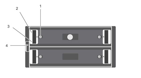
Figure 1: SC180 Front-Panel Features and Indicators
| Item | Name | Panel | Description |
| 1 | Drawer specific anti-tamper locks |  |
Locks the drawer shut using a Torx T20 screwdriver until the red arrows point to the locked icon (away from the center of the chassis). |
| 2 | Drawer specific left and right side status indicators |  |
|
| 3 | Drawer specific left and right side expansion enclosure activity indicators | 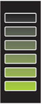 |
Activity Bar Graph: Six variable-intensity LEDs dynamically displaying access of the drives in that specific drawer. |
| 4 | Status indicator for expansion enclosure | 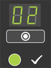 |
|
 |
|
||
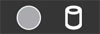 |
|
||
 |
|
||
 |
Drawer 2 Fault: Amber when a drive, cable, or sideplane fault has occurred in drawer 2 |
NOTE: Both drawer fault LEDs (and all contained DDIC LEDs) will flash when the expansion enclosure indicator is set to On in Storage Client.
Back-Panel Features and Indicators
The SC180 back panel shows power, connectivity, and fault indicators.
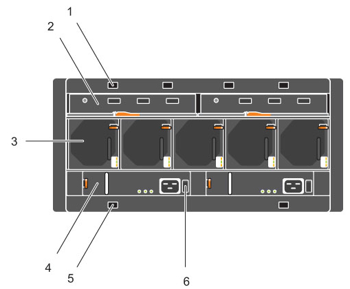
Figure 2: SC180 Back-Panel Features and Indicators
| Item | Name | Icon | Description |
| 1 | Optional cable retention positions (4) | - |
|
| 2 | Expansion Enclosure Modules (2) | - |
|
| 3 | Cooling fans (5) | - |
|
| 4 | Power supply units (2) | - |
|
| 5 | Optional cable retention positions (4) | - |
|
| 6 | Power switch (2) | - |
|
EMM Features and Indicators
An SC180 expansion enclosure includes two Enclosure Management Modules (EMMs) in two Storage Bridge Bay (SBB) interface slots.
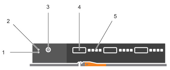
Figure 3: SC180 EMM Features and Indicators
| Item | Name | Icon | Description |
| 1 | Fault LED |  |
|
| 2 | Power LED |  |
|
| 3 | Console port | - |
|
| 4 | SAS ports | - |
|
| 5 | SAS port link status indicators | - |
|
Fan Module Features and Indicators
SC180 expansion enclosures include five fan modules in five interface slots.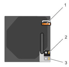
Figure 4: SC180 Fan Module Features and Indicators
| Item | Name | Icon | Description |
| 1 | Release latch | - |
|
| 2 | Module OK |  |
|
| 3 | Fan fault |  |
|
Back to Top
PSU Features and Indicators
SC180 expansion enclosures include two Power Supply Units (PSUs) in two interface slots.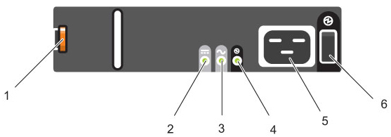
Figure 5: SC180 PSU Features and Indicators
| Item | Name | Icon | Description |
| 1 | Release latch | - |
|
| 2 | PSU fault |  |
|
| 3 | AC fault |  |
|
| 4 | Power OK |  |
|
| 5 | Power outlet | - |
|
| 6 | Power switch | - |
|
Separate and unique conditions are indicated if all three LEDs are in the same state:
- If all three LEDs are off, then there is no AC power to either PSU.
- If all three LEDs are on, then the General Enclosure Management (GEM) software has lost communication with the PSU.
Cause
.
Resolution
.
Affected Products
Dell Storage SC180Article Properties
Article Number: 000141445
Article Type: Solution
Last Modified: 10 Dec 2025
Version: 5
Find answers to your questions from other Dell users
Support Services
Check if your device is covered by Support Services.