Precision 3430 Workstation Teardown Removal Guide for Customer Replaceable Parts (CRUs)
Summary: This article is a guide to those parts of the Precision 3430 workstation that Dell considers it OK for anyone to remove and replace.
Symptoms
These guides take you step by step through the safe removal of the customer replaceable unit (CRU) parts of a Precision 3430 Small Form Factor (SFF) Workstation. CRUs are the parts of the computer that should not need an engineer to remove or replace. The guides also include figures to reference what is involved.
Cause
Not applicable
Resolution
Table of Contents:
1. Removal Guide
If these guides do not cover what you are looking to do, then reference your System Manual.
The article below provides information about safe practices to consider before working with electrical equipment.
2. Removal Instructions
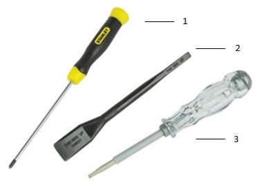
| 1 | Small Phillips head screwdriver | 2 | Plastic Scribe |
| 3 | Small flat head screwdriver |
-
Pre-removal instructions before removing the side cover:
-
During installation or removal of any hardware, always ensure that all data is backed up properly.
-
Disconnect any telephone, network, or USB cables from the computer.
-
Disconnect the computer and all attached devices from their electrical outlets.
-
-
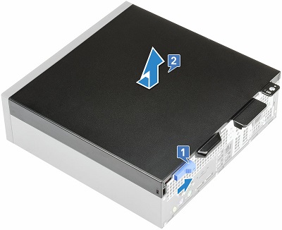
Press the blue latch towards the middle of the rear of the chassis until you hear a click noise. This indicates that the cover is unlocked. [1]
-
Slide the cover towards the rear of the chassis and lift it up and away from the computer. [2]
-
Pre-removal instructions before removing the front bezel:
-
During installation or removal of any hardware, always ensure that all data is backed up properly.
-
Disconnect any telephone, network, or USB cables from the computer.
-
Disconnect the computer and all attached devices from their electrical outlets.
-
Remove the Side Cover.
-
-
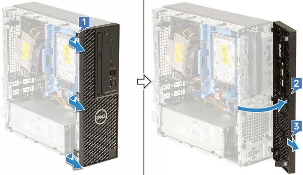
Pry up the three retention tabs along the top of the bezel [1] and rotate down towards the bottom of the bezel [2] to remove it from the chassis. [3]
-
Pre-removal instructions before removing the expansion cards:
-
During installation or removal of any hardware, always ensure that all data is backed up properly.
-
Disconnect any telephone, network, or USB cables from the computer.
-
Disconnect the computer and all attached devices from their electrical outlets.
-
Remove the Side Cover.
-
-
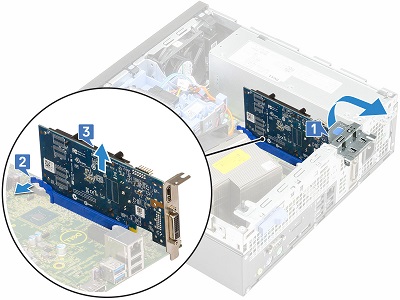
Check for any additional cables from the card and disconnect them from the computer. Press and rotate the blue metal latch [1] to unlock the cards. Pull the release tab at the base of the card [2] and lift it out of the computer. [3]
-
Pre-removal instructions before removing the memory:
-
During installation or removal of any hardware, always ensure that all data is backed up properly.
-
Disconnect any telephone, network, or USB cables from the computer.
-
Disconnect the computer and all attached devices from their electrical outlets.
-
Remove the Side Cover and Air Shroud.
-
-
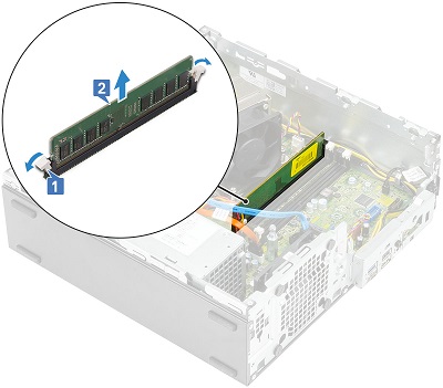
Pull the securing clips away from the memory [1] and lift the memory up and out of the computer. [2]
-
Pre-removal instructions before removing the hard disk drive:
-
During installation or removal of any hardware, always ensure that all data is backed up properly.
-
Disconnect any telephone, network, or USB cables from the computer.
-
Disconnect the computer and all attached devices from their electrical outlets.
-
Remove the Side Cover.
-
-
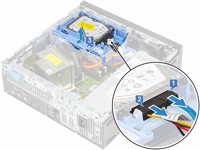
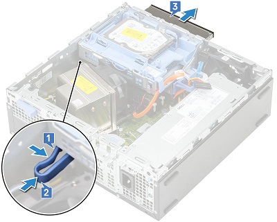
Disconnect the cables [1,2] from the rear of the hard drive and push on the release tab and remove the hard drive from the computer. [3]
-
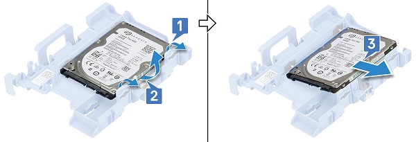
For a 2.5" hard drive, pull one side of the bracket away far enough to disengage the securing pins [1,2] and lift the hard drive out of the bracket. [3]
-
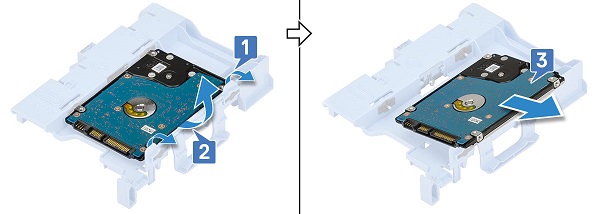
For a 3.5" hard drive, pull one side of the bracket away far enough to disengage the securing pins [1,2] and lift the hard drive out of the bracket. [3]
-
Pre-removal instructions before removing the hard disk drive and optical drive module:
-
During installation or removal of any hardware, always ensure that all data is backed up properly.
-
Disconnect any telephone, network, or USB cables from the computer.
-
Disconnect the computer and all attached devices from their electrical outlets.
-
Remove the Side Cover and hard drive.
-
-
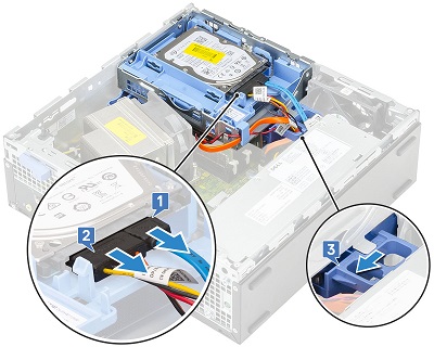
Disconnect and unroute the hard drive cables from the drive and release catch [1,2] slide the release catch towards the rear of the chassis to unlock the module. [3]
-
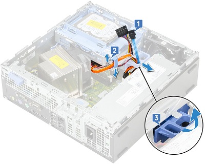
Unroute the optical drive cables from the release catch [1,2] and lift the module up by the release catch. [3]
-
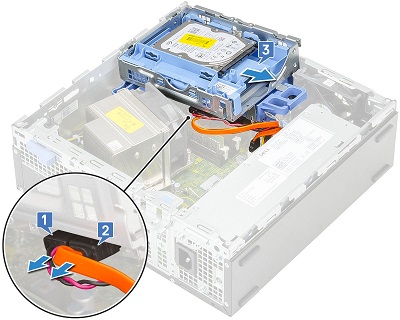
Disconnect the optical drive cables from the drive [1,2] and lift the module out of the computer. [3]
-
Pre-removal instructions before removing the optical drive:
-
During installation or removal of any hardware, always ensure that all data is backed up properly.
-
Disconnect any telephone, network, or USB cables from the computer.
-
Disconnect the computer and all attached devices from their electrical outlets.
-
Remove the Side Cover, Front Bezel, hard drive, and the hard drive and optical drive module.
-
-
Squeeze the blue release catch [1] and push it towards the front of the computer [2], then pull the drive out the front of the computer. [3]
-
Pre-removal instructions before removing the M.2 PCIe SSD card:
-
During installation or removal of any hardware, always ensure that all data is backed up properly.
-
Disconnect any telephone, network, or USB cables from the computer.
-
Disconnect the computer and all attached devices from their electrical outlets.
-
Remove the Side Cover, Front Bezel, and Hard Disk Drive and Optical Drive Module.
-
-
Remove the screw that secures the card to the motherboard. [1] Lift the card at a 45% angle and pull out of its connector on the motherboard. [2] Peel the thermal pad from the motherboard for reuse if needed. [3]

-
Pre-Removal Instructions Before removing the Internal Speaker:
-
During installation or removal of any hardware, always ensure that all data is backed up properly.
-
Disconnect any telephone, network, or USB cables from the computer.
-
Disconnect the computer and all attached devices from their electrical outlets.
-
Remove the Side Cover, Front Bezel, and Hard Disk Drive and Optical Drive Module.
-
-
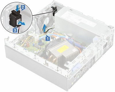
Disconnect one end of the speaker cable from the motherboard [1] and press the release tab [2] and pull the speaker out of the computer. [3]
-
Press in and hold the tabs on the speaker [2] and then slide it out the front of the computer [3].
-
Pre-removal instructions before removing the coin-cell battery:
-
During installation or removal of any hardware, always ensure that all data is backed up properly.
-
Disconnect any telephone, network, or USB cables from the computer.
-
Disconnect the computer and all attached devices from their electrical outlets.
-
Remove the Side Cover.
-
-
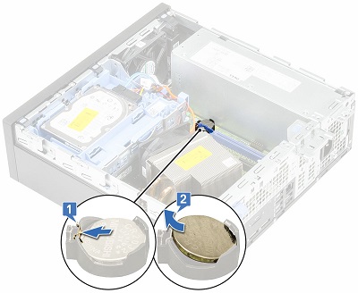
Press the release latch away from the battery until the battery pops up from the socket [1]. Lift the battery out of the computer. [2]
| If you require further assistance, contact Technical Support. | ||
| Contact Us | ||