OptiPlex 7070 Ultra Teardown/Removal guide for customer replaceable units (CRUs)
Summary: This article is a guide to the removal of those parts of the Dell OptiPlex 7070 Ultra desktop, that dell considers it OK for anyone to remove and replace.
Symptoms
These guides will take you step by step through the safe removal of what are considered to be the Customer Replaceable Unit (CRU) parts of an OptiPlex 7070 Ultra system. (CRUs are the parts of the system that shouldn't need an engineer to remove or replace.) The guides will also include pictures to reference what's involved.
Table of Contents:
Removal Guide
If these guides do not cover what you are looking to do, then you will want to reference your System Manual.
The article below provides information on the safe practises you should take into consideration before working with electrical equipment.
Removal Instructions
 Note: Please click on the title of the section you want to open below, to see the contents.
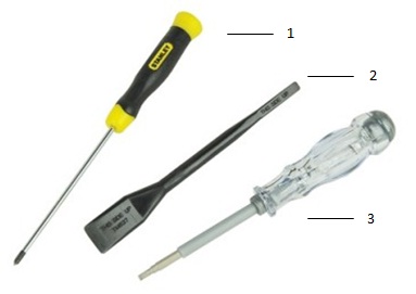
| 1 | Small Phillip's head screwdriver | 2 | Plastic Scribe |
| 3 | Small Flathead screwdriver |
 Note: Be aware that using a large Phillips or Flat Head screwdriver may result in damage to the head of the screws. This would make their removal impossible without speciality tools, that aren't available to our onsite engineers.
-
Pre-Removal Instructions Before removing the Front Cover :
-
During installation or removal of any hardware always ensure all data is backed up properly
-
Disconnect any telephone, network, or USB cables from the computer
-
Disconnect the computer and all attached devices from their electrical outlets
-
-
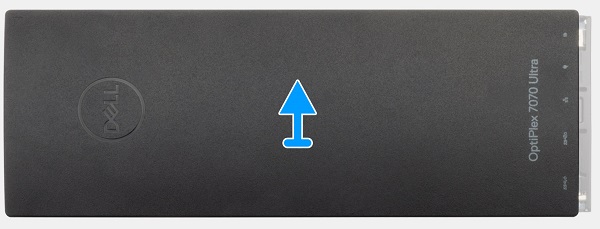
With the system on it's back, push the front cover towards the top of the PC until it releases from the chassis

-
Lift the cover up and off of the computer
-
Pre-Removal Instructions Before removing the 2.5" Hard Disk Drive (HDD) :
-
During installation or removal of any hardware always ensure all data is backed up properly
-
Disconnect any telephone, network, or USB cables from the computer
-
Disconnect the computer and all attached devices from their electrical outlets
-
Please remove the Front Cover
-
-
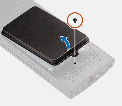
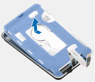
The HDD is located on the back of the system in a swing-out panel. Remove the single screw that secures the HDD assembly to the back of the system and open the door with the HDD
-
Lift the securing tab on the ZIF connector and disconnect the cable and un-route it from the slot on the chassis and remove the HDD and door from the system
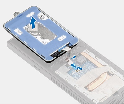
 Note: Take note of the routing of the HDD cable, before you remove it. Remember you will need to re-route this cable when you fit the new HDD and you don't want to crimp and damage the ribbon cable.
-
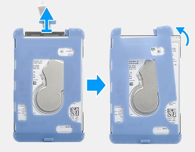
Pull the blue rubber tab on the protective sleeve at the side opposite the HDD cable, and lift the HDD module out of the Assembly door
-
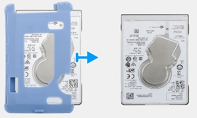
Disconnect the cable from the HDD pull one corner of the open side of the protective sleeve from the bottom of the HDD
-
Once you have one side of the HDD out of the open end of the protective sleeve, pull the sleeve off of the HDD
-
Pre-Removal Instructions Before removing the M.2 SSD Card:
-
During installation or removal of any hardware always ensure all data is backed up properly
-
Disconnect any telephone, network, or USB cables from the computer
-
Disconnect the computer and all attached devices from their electrical outlets
-
Please remove the Front Cover
-
-
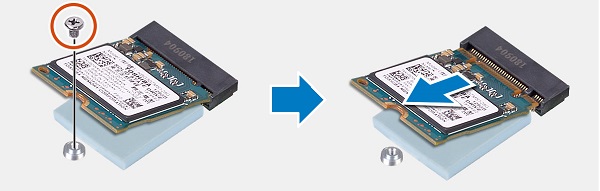
The SSD connector is located in the bottom right-hand side of the system. Remove the single screw which secures the end of the SSD card to the chassis
-
When the card pops up at an angle, pull the card out of the connector and out of the PC
-
Pre-Removal Instructions Before removing the Memory :
-
During installation or removal of any hardware always ensure all data is backed up properly
-
Disconnect any telephone, network, or USB cables from the computer
-
Disconnect the computer and all attached devices from their electrical outlets
-
Please remove the Front Cover
-
-
The memory is located in the centre of the system, lift the absorber panel from on top of the memory DIMM
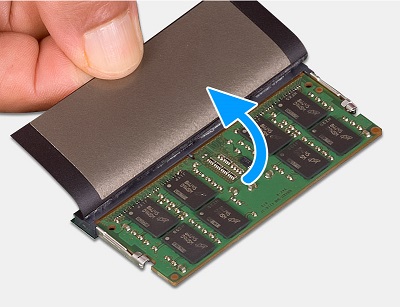
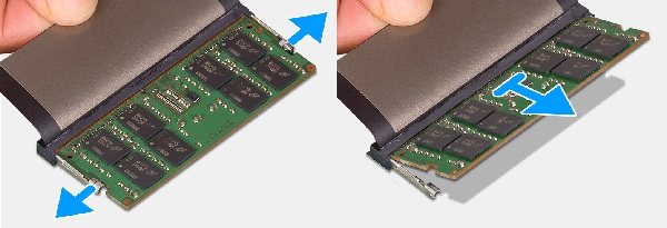
-
Pull the tabs on either side of the DIMM apart to release the memory DIMM and lift the DIMM up and out of the slot and the PC
 Note: Please repeat Steps 2 and 3 for any additional Memory DIMMs located in the system.
-
Pre-Removal Instructions Before removing the System Fan:
-
During installation or removal of any hardware always ensure all data is backed up properly
-
Disconnect any telephone, network, or USB cables from the computer
-
Disconnect the computer and all attached devices from their electrical outlets
-
Please remove the Front Cover
-
-
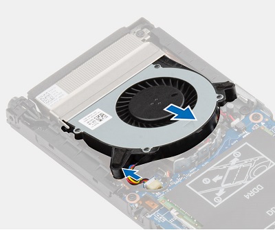
The system fan is located at the top edge of the chassis, release the fan from the retention hook and disconnect the coin cell battery cable from the motherboard
-
Lift the system fan out of the PC
-
Pre-Removal Instructions Before removing the Coin Cell Battery :
-
During installation or removal of any hardware always ensure all data is backed up properly
-
Disconnect any telephone, network, or USB cables from the computer
-
Disconnect the computer and all attached devices from their electrical outlets
-
Please remove the Front Cover and System Fan
-
-
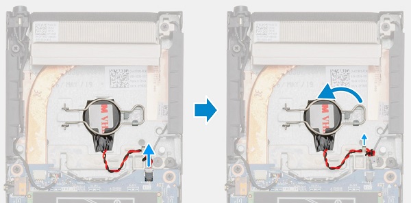
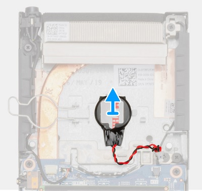
The coin cell battery is located under the system fan, once the system is removed, disconnect the coin cell battery cable from the motherboard. Release the retention clip from its securing hook and swing it fully open
-
Lift the battery out of the PC
-
Pre-Removal Instructions Before removing the WiFi Wireless Card:
-
During installation or removal of any hardware always ensure all data is backed up properly
-
Disconnect any telephone, network, or USB cables from the computer
-
Disconnect the computer and all attached devices from their electrical outlets
-
Please remove the Front Cover
-
-
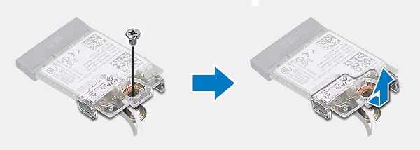
The WLAN card is located at the bottom left-hand side of the chassis, remove the single screw from the bracket securing the card to the motherboard and remove the bracket
-
Disconnect the antenna cables (These are small press-stud connectors and pop of with a little pressure.) from the card and lift the card out of the socket and the PC

| If you require further assistance, please contact technical support. | |
| Contact Us | |