VMAX, PowerMax: Non-Disruptive Migration for the IBMi Host Platform
Summary: The Dell VMAX and PowerMax enterprise storage platform families support storage-based Non-Disruptive Migrations (NDM) to migrate business-critical host systems to new storage arrays without application downtime. With the release of the PowerMaxOS 5978.444.444 code family, NDM support is added for the IBMi host platform. NOTE 1: For IBMi systems that also use Dell's native STM software toolkit (SRDF/TimeFinder Manager for IBMi), there are some additional considerations when the (optional) final step in the NDM process is done for a device-identity reset (unspoofing) of the migrated devices. Read the instructions provided below, prior to performing the identity reset! NOTE 2: The device identity reset, also mentioned as an "unspoof" operation, has implications for the next initial program load (IPL) phase after the unspoof. Read further details below. ...
Instructions
Environment for Support:
NDM for IBMi is available for supported IBMi host systems that are connected to VMAX or PowerMax arrays running release 5978.444.444 or later of the PowerMaxOS.
This is for IBMi Logical partitions (LPARs) running on the IBM Power Server platform Power6 or later and running the IBMi operating system version i6.1.1 or later. The VMAX or PowerMax general e-Lab support matrix provides details and lists the supported Fibre Channel (FC) IBMi I/O-Adapters (IOAs), aka Host Bus Adapters (HBAs). NDM is also supported when IBMi is a client LPAR with assigned virtual I/O resources from an IBM Virtual I/O Server (VIOS). With the IBM VIOS/VFC (NPIV) feature, virtual FC adapters (vFCs) are assigned to the client LPARs for connecting to the storage array using supported SAN switches.
vFCs act as a pass-through for the host disk connectivity; From the host-side, this is fully transparent and all supported features from the storage array are available in that virtualized adapter setup as well.
Back-ground and High-level migration scenario:
Symmetrix Remote Data Facility (SRDF) was developed in the early 1990s as a Disaster Recovery (DR) replication technology for the Dell Enterprise Storage arrays. It has also been used for many years to perform storage-based migrations from one array to another. That is, connect the OLD and NEW array's "back-to-back" and copy the data volumes when performing a technology refresh by implementing a new storage array. Although the SRDF copy process of the volumes or Logical Units (LUNs) is transparent to the attached host systems, traditionally it always required a short offline "cut-over" window when the copy-process was completed from the source volumes (R1s). The target (new) volumes (R2s) were Read/Write-enabled and the host systems' FC connections were pointed (through SAN zoning and masking) to the new array.
SRDF/Metro was introduced with the VMAX All Flash storage array family. SRDF/Metro provides true active/active host access to the source- (R1) and target- (R2) volumes from both arrays. SRDF/Metro works with supported host multi-path drivers for disk access. This includes the native IBMi Dynamic Multi Path (DMP) protection for disk paths. IBMi DMP automatically detects if there are multiple FC paths to the same disk device. It also provides a basic but effective "round robin" load-balancing scheme to spread the disk I/O workload across the available FC adapter paths. IBMi DMP provides automatic path failover when connections may fail, by redirecting the disk I/O operation to one of the remaining active paths. When failing connections are restored, IBMi automatically recovers those paths and starts sending disk I/O to these paths again.
NDM with METRO and precopy option is based on the underlying SRDF/Metro technology to provide simultaneous access to the old and the new storage devices.
CREATE Phase:
When an SRDF/Metro replication device pair (R1>R2) is created, the same R1 device identity is presented from the R2 device in the target array. In essence, the same disk serial-ID and device WWPN are presented from both devices. Initially the new R2 device is in a state of AA-NR/DEV-INACT (Active/active-Not Ready/ Device Inactive). Once the R1>R2 device pair is synchronized, it can enter into an active/active state by enabling Read and Write access to the R2 volume.
READY_TARGET Phase:
When the path from the IBMi LPAR to the R2 device is now enabled (SAN Zoning already in place and Masking for the new array activated by NDM readytgt command), the IBMi host discovers new FC paths to the existing disk device. In an IBMi NDM scenario, the active/active R1 + R2 devices are presented.
COMMIT Phase:
By removing access to the R1 devices, the IBMi host now loses access to the old array's paths, but continues to run on the R2 devices using the paths to the new array. Once this is done, the SAN-zoning to the old array can be removed. The "reset multipath" utility on the IBMi system should be run, in order to stop using the old inactive paths and also stop any error messages associated with these now "missing" paths. It may take an Initial Program Load (IPL) aka reboot, to permanently remove the old inactive paths, and its associated DMPxxx disk hardware resources from the IBMi hosts' device configuration database (IBMi storage management information repository), but this is not a mandatory IPL, it can also wait until the next planned IPL. For removal of these "stale" devices: STRSST>Start Service Tool>Hardware Service Manager>Failed and Non-reporting Hardware: select all old disk resources DMPxxx for removal with option 4 and confirm that by pressing enter.
Considerations when using Dell STM
STM, also often mentioned as the "storage copy services toolkit" for IBMi replication control for VMAX, PowerMax storage is running as a native software application on one or more IBMi hosts. It can control remote replication for supported SRDF configurations and local replication for SnapVX snapshots on VMAX, PowerMax arrays. STM comes in two flavors: Standard Features edition and Extended Features edition.
STM uses in-band communication to the storage array across the FC paths, it uses small dedicated devices, also mentioned as gatekeepers for its system calls. The gatekeepers for IBMi are special small D910 GK-type devices that remain in the non-configured disk units section. These gatekeepers do not support multipath, multiple single-pathed gatekeepers are typically presented on the same redundant set of paths that are used for the regular ASP1 disks. It is recommended using a minimum of four gatekeepers. Gatekeepers are not part of the NDM migration process, hence after the migration, the access to gatekeepers from the old array is removed and new gatekeepers from the new array are presented.
Standard Features:
This is used for systems that only use a *SYSBAS storage configuration. *SYSBAS means the System ASP1 + any additional User-ASP's (ASP 2-32). STM is only installed on the source node, and it controls the replication pairs for all disks in *SYSBAS as one undividable entity. When changes occur in the underlying disk configuration; that is disk serial number changes caused by the NDM "unspoofing" operation, it is sufficient to perform the STM DISCOVER command on the IBMi source host. Run the DISCOVER option when the gatekeepers from the new array are presented. This updates the local symapi database in the Integrated File System (IFS) on the host (location= /var/symapi/db). The STM screens now also reflect the new disk serial numbers. In case any issues are observed in the replication device pairing within STM, it is also possible to only use the install option to start with a fresh configuration setup. This has no effect on the replication pairing setup that is already configured on the VMAX-PowerMax storage array. For a clean scratch install/setup, first document the associated PATHS and STEPS in the current configuration (GO MAINCTL>1, IMAGES>select option 2, for the SYSTEM image> create screen capture for the PATHS screen as per the below example:

Exit STM, Delete the /var/symapi folder and its subfolders. Delete the EMCCTL library. Run STM install the program again. Run CRTSYMAPI. GO MAINCTL, associate the same PATHS again as were configured previously. STM now detects and displays the status of the active replication pairing from the VMAX-PowerMax storage array. STM operations are ready to be resumed now.
Extended Features:
This is used for systems that use an IBMi PowerHA cluster setup with one or more "switchable" iASP (independent ASP). In this scenario, only the iASP is replicated and this iASP or replica's thereof can be presented to the nodes within the PowerHA cluster. Each cluster node is already active on its own *SYSBAS (ASP1). The iASP is configured as a switchable resource within the shared cluster device domain. There are typically two or four nodes in the cluster; that is as per the below example diagram for a 4-node cluster with the production node as source and with a remote DR target-node and a SnapVX backup-node on both sides:
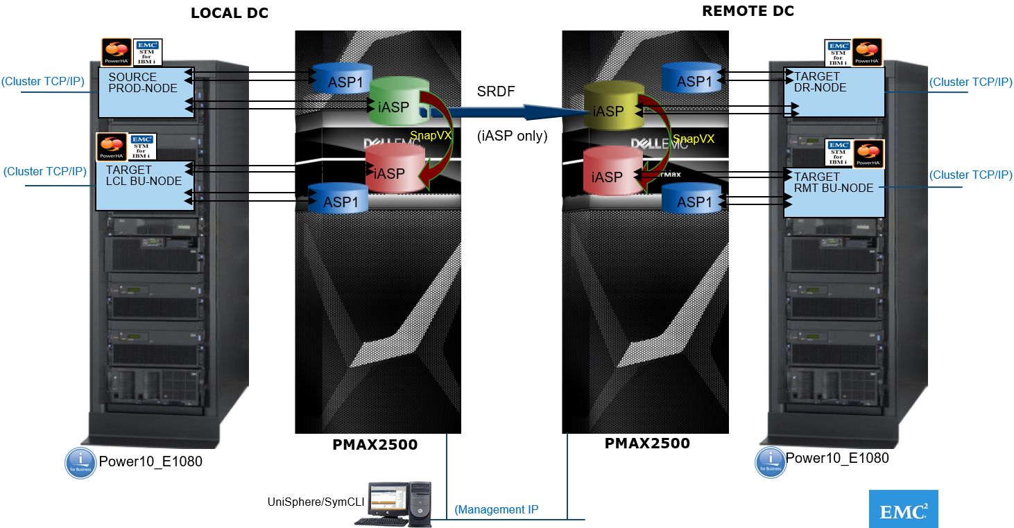
No IPL from any node is required to use the iASP or its replicas. When the iASP disks are presented to any node within the cluster, it requires the VARY ON command to make the iASP available to that node. In a PowerHA setup, the STM Source version is installed on the Source node (in EMCCTL Library). On all other nodes (either SRDF or SnapVX target replica's), the Target version is installed (in EMCCTLC Library). With all nodes being active, there are dependencies and checks and balances built into STM for certain operations in this setup that is removing disk access for a node is prohibited if the iASP is still in VARY ON state for that node. For the internode communication, there is an STM server job running in the EMCCTL subsystem on all nodes. This job communicates within the nodes across the cluster IP interfaces. Typical STM operations can be run from any node within the cluster. This requires that a set of the same STM disk, adapters, and path configuration files be available on each node. During the initial setup of STM for PowerHA, these files are configured using MAINCTL option-16 from the source node and this also propagates these files to the target-nodes, that are the IASPS, ISRCIOA, and IMAGE files in the STM install libraries EMCCTL and EMCCTLC. These files can be displayed as well, that is with DSPPFM EMCCTL/IMAGE. The files contain information about disks and disk adapters used for the iASP configuration. Adapter-ID's and disk serial numbers are stored in these files and used in the STM operations.
Now, consider the impact of a disk serial number change that happens when the NDM unspoofing operation is done. The STM configuration files still contain the old disk serial numbers. Most STM operations are no longer functional until these configuration files are updated. Updating and propagating these files can be done by following the same process as during the initial STM install when MAINCTL>Option-16 (configure iASP) is run while the iASP disks are made available to the target nodes in the respective PATH-STEP. Once these files are updated, STM iASP operations function as expected again. If any issues arise, consider to only run a scratch install again of STM for the source- and target-nodes, including the option-16 to configure the iASP PATH's/STEP's and create or propagate the STM configuration files.
Note: During this fresh install, do NOT select the option to keep the existing configuration files, as these still contain the old disk serial numbers.
Registered users with a Dell Support account can view the SRDF/TimeFinder Manager for IBM i for further relevant information about these STM editions.
Considerations for the next IPL after the device-identity reset, aka "unspoof" operation
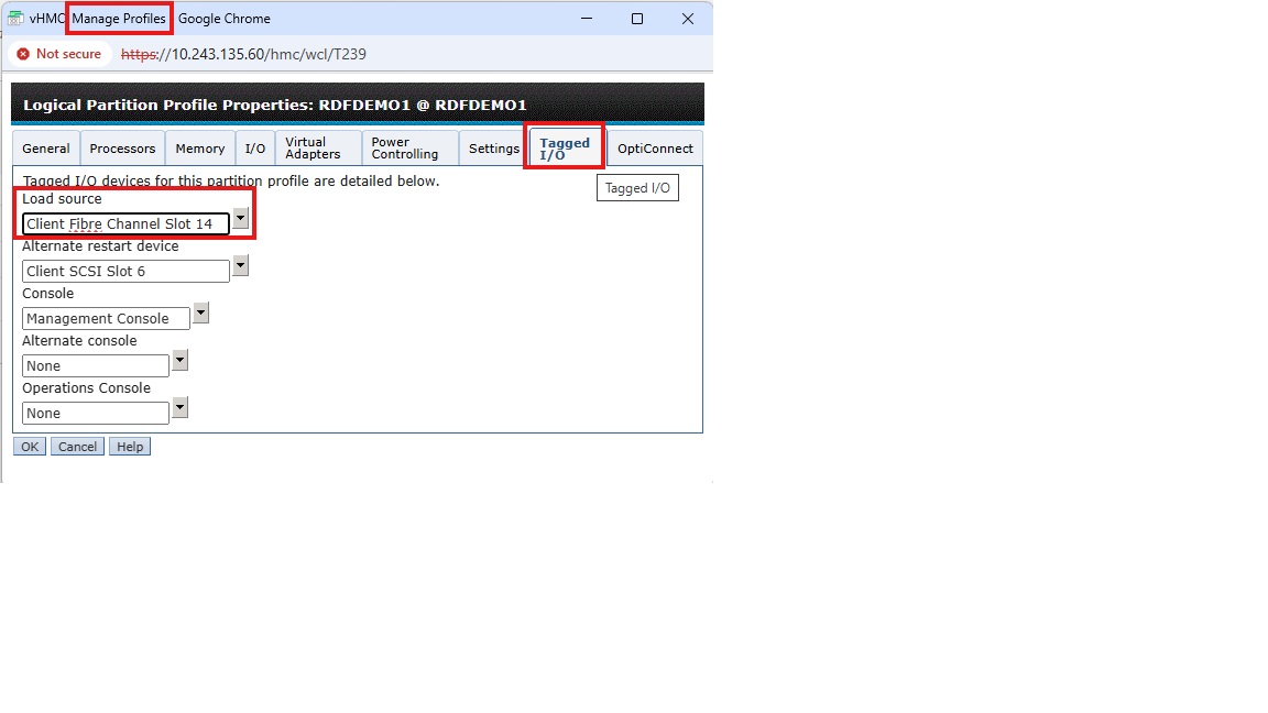
The NDM unspoof operation changes the disk serial numbers. This can only be done when the IBMi LPAR is down. When this operation is done post-migration in a planned offline maintenance slot, there are some considerations. The activation of the IBMi LPAR is controlled from the IBM PowerServer Hardware Management Console (HMC), the HMC provides the Hypervisor function for the IBM PowerVM virtualization. On this HMC, each LPAR has at least one LPAR profile with details about the LPAR configuration, that is CPU/MEM, adapters, so forth. When the LPAR is IPL-ed (IPL= Initial Program Load = boot sequence) for the first time, it reads the configuration details from the selected profile. A special tab in the profile is called "Tagged I/O." The Tagged I/O settings define where the LPAR must search for the Load Source (LS) (= bootdisk) during a B-type IPL, and for the "alternate restart device" during a D-type IPL, that is DVD or tape. If the LPAR has successfully IPL-ed for the first time, it does not have to read the profile again, as the last IPL info gets stored on the hypervisor. At next IPL, the default setting of "current configuration" is used, unless the LPAR profile is specifically selected again. If there are specific changes for the LS controller or for the LS disk details in between IPLs, then the LPAR does not accept the changed LS disk and the IPL fails. This happens, IF: The LPAR is activated with "current configuration" option, or if the Tagged I/O LS adapter is set to "none." The change of the LS disk serial number is such a change that the LPAR does not accept it and where an activation with the correct profile selected is required.
The screen capture below shows the traditional HMC LPAR profile view with a valid LS adapter selected:
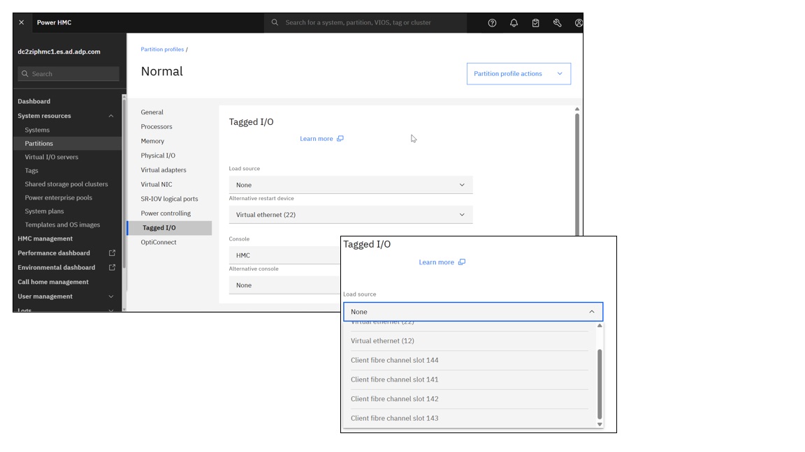
The image below shows the same information in the modern version view of the HMC v10 with VIOS 3.x /4.x.
Other useful information is contained in the PowerMax and VMAX: Non-Disruptive and Minimally Disruptive Migration Best Practices and Operational Guide
======================================================================================
PRACTICAL IBMi NDM Procedure:
#NDM (Non Disruptive Migration) procedure for IBMi host environments.
#From VMAX>>>VMAX, VMAX>>>PMAX, PMAX>>>PMAX
#Written: Q4-2021
#Author: Wopke Hoekstra CSA IBMi Global Practice
#Version: 5
==========================================================================================

# Just for reference: PowerMax OS 5978 Levels:

Name        Release Level/Code
Elm         5978.144.144
Elm SR      5978.221.221
Foxtail     5978.444.444
Foxtail SR  5978.479.479
Hickory     5978.669.669
Hickory SR  5978.711.711
==========================================================================================
#PREREQS:
# MINIMUM Microcode Requirements: Foxtail (NDM IBMi support and NDM METRO-Mode available)
# MINIMUM of 2 RF directors per array are required
# Central external UniSphere/SE (SymCLI) server required with access to the source and target arrays
# MINIMUM SE version of 9.1
====================================================================================================

#Actual Customer Environment where this procedure was used:
# "OLD" VMAX: SN# ckxxxxxxxxx/ckxxxxxxxxx / 5978.479.479
# "NEW" PMAX: SN# ckxxxxxxxxx/ckxxxxxxxxx / 5978.479.479

============================================================================================================
#Suggested NDM procedure: METRO NDM with Pre-Copy
#Also refer to the DELL EMC PowerMax NDM Whitepaper: Paragraph 3.2.4 / page 120
============================================================================================================

#PROCEDURE: Metro-based NDM with precopy
#NOTE: (NDM with precopy allows end users to copy application data from the source array to target array while the application is still running on the source array)

#SAN requirements:
#Existing Host FC IOA ports/WWPN's will be used to also zone to the new target array's FA-ports. NO NEED for additional host FC connections.
#NOTE: The NEW array needs to be connected to the same SAN Fabric's as the OLD array.
#For each zone; add the desired target-array's FA-port WWPN into the existing zone (already containing the host initiator WWPN and OLD array FA-port WWPN)
#Or alternatively create new zones with same initiators to the new target-array's FA-ports

#NOTE: For LPAR's using VIOS/VFC(NPIV) connections and when the environment is setup for Live Partition Mobility, the vFC's secondary WWPN will be included in the zoning/masking.
#The secondary WWPN's will not be active and are not in the source array's Login History Table. NDM does not accept inactive WWPN's to be in the IG of the source host, hence the NDM VALIDATE and CREATE commands will fail.
#WORKAROUND: Temporarily remove the secondary WWPN's from the source LPAR IG. After the migration, simply add these secondary WWPN's back into the new IG on the target array.

#Setup-phase:
#symdm –src_sid <SN of Source> -tgt_sid <SN of target> environment -setup
symdm -sid 008 -tgt_sid 661 environment setup
#NDM RDFGroup will be created.

Now modify the SAN zoning to include the target-array FA-ports.
#NOTE: No devices are presented from the target-array yet.
#NOTE: You can already check if the existing initiator-WWPN's are actively logging in to the new array
symaccess -sid 661 list logins -dirport 1d:4

#To check the environment at any time:
#symdm –src_sid <SN of Source> -tgt_sid <SN of target> environment -validate
symdm -src_sid 336 -tgt_sid 662 environment -validate
symdm -src_sid 008 -tgt_sid 661 environment -validate

Other commands to display further details:
symdm -sid 336 -environment list
symcfg -sid 336 list -rdfg all
symcfg -sid 008 list -rdfg all

#NOTE: Take a copy of the source-array's masking database before the activity:
symaccess -sid 336 list view -all -v -detail>masking336_24Nov2021.txt
symaccess -sid 008 list view -all -v -detail>masking008_24Nov2021.txt

#Create Phase (with precopy: (run validation prior to execution))
#This creates an SRDF/Metro session with NDM attributes and puts the SRDF/Metro pair into adaptive copy disk mode.
#It starts syncing data from R1 to R2.
#Bias is on the Metro-based NDM source.
#symdm create –src_sid <SN of Source> -tgt_sid <SN of target> -sg <SG to be Migrated> [-tgt_srp <target SRP>] [-tgt_pg <target PG>] -precopy
#First validate:
symdm create -src_sid 008 -tgt_sid 661 -sg SG_IBMPROD1_1 -precopy -validate
#Then execute:
symdm create -src_sid 008 -tgt_sid 661 -sg SG_IBMPROD1_1 -precopy

#Check NDM status:
#symdm –sid xxx list (-v) (-detail)
#symdm –sid<SN of SRC or TGT> -sg <SG to be Migrated> list –v –pairs_info -detail (shows device pairing)
#symrdf list -sid xxx (-rdfg xxx) (-sg xxx)
#symstat –sid <SRC SN> –rdfg<RDFG of Migration> –type RDF –i xx
symdm -sid 008 list

#ReadyTGT Phase:
#Moves RDF pair state from adaptive copy mode to Active/Active(in case of witness protection) or Active/Bias (without witness protection).
#Target devices are moved into a read/write mode, It puts the NDM pair in Active/Active or Active/Bias mode
#Masking view is created on the target array using the masking elements created during the create command.
#symdm –sid <SRC or TGT SN> -sg <SG to be Migrated> readytgt
symdm -sid 008 -sg SG_IBMPROD1_1 readytgt

#Check status:
#symdm –sid xxx list (-v) (-detail)
#symrdf list -sid xxx (-rdfg xxx) (-sg xxx)
symdm -sid 008 list

#On the IBMi LPAR, check for new detected FC paths (to the devices on new PowerMax)
#Logon to LPAR, go into System Service Tools: STRSST and go to "work with disks"> "disk configuration"> "9.Disk Paths"
#Let the system discover the paths, this may take a few minutes, just hit F5 to refresh the disk path status screen and verify all disks have the new paths added.

#Commit Phase (this is the actual cutover to the new array):
#symdm –sid <SRC or TGT SN> -sg <SG to be Migrated> commit
symdm -sid 008 -sg SG_IBMPROD1_1 commit

#The masking views will be removed on the old source array.
#On the IBMi LPAR, check for the old paths going into "failed" status (these failing paths are the paths to the old source array)
#Zoning cleanup: Remove the old array's FA-ports from the respective zones for this LPAR.
#Use SST procedure to run MULTIPATH RESETTER macro (this will prevent further error messages being sent to the QSYSOPR MSGQ until the system is IPL-ed)
#After next planned IPL, the path status will be correct again, with only the new active paths listed.

#ONLINE MIGRATION COMPLETED!
============================

#Remove NDM environment (ONLY after last migration is completed):
#symdm -sid xxx -environment -list
#symdm –src_sid <SN of Source> -tgt_sid <SN of target> environment -remove
symdm -sid 008 -tgt_sid 661 environment -remove
============================================================================================================

#Reset Device external Identity (un-Spoof) (Optional OFFLINE operation).
#Resetting the target's device external identity back to the original array-based identity of the NEW array (changes the IBMi disk serial number (= Vol.ID + Array-ID))
#THIS REQUIRES A SHUTDOWN OF THE IBMi LPAR!
#Can be done as planned activity when the IBMi LPAR is doing an offline activity, and will be re-IPL-ed... I.e. for full backup, scheduled IPL, etc.

#NOTE: When STM (SRDF/TimeFinder Manager for IBMi) is used on the migrated LPAR, it requires a reconfiguration or as a minimum a DISCOVER command action, due to the changing of the LPAR's disk serial numbers.
#Refer to KB article 193832 for more info and procedure.
Only unmasked devices can be unspoofed, so first record and save the details of the current masking view, then delete the MV, unspoof and then re-create the MV.
symaccess -sid xxx show view -name xxxxxxxx >masking_xxxxxxxx.txt
symaccess -sid xxx delete view -name xxxxxxxx
Display disk identity details:
symdev -sid xxx list -identity_set
symdev -sid xxx list -identity -sg <sg-name>
For a single device:
symdev -sid xxx reset -identity -dev xxx -nop
For a range of devices:
symdev -sid xxx reset -identity -devs xxx:xxx -nop

symaccess -sid xxx create view -name xxxxxxxx -sg xxxxxxxx -pg xxxxxxxx -ig xxxxxxxx
symdev -sid xxx list -identity -sg <sg-name>
Verify from the IBM HMC that in the LPAR profile, in the "Tagged I/O" -tab, that the LS controller is set to the correct FC adapter.
Do NOT leave the "Tagged I/O" LS controller setting empty with "none" selected.
IPL with B-Normal option and select the LPAR profile for the IPL, do NOT leave it to the default option of "current configuration."
Now IPL the LPAR and after system is back online, verify the disk serial numbers from SST.
The serial IDs should now reflect the new arrays symdev ID and array serial number.
=== End of Procedure ===