OptiPlex 5070 Small Form Factor (SFF) Teardown removal guide for customer replaceable unit (CRUs)
Summary: This article is a guide to the removal of those parts of the Dell Small Form Factor OptiPlex 5070 desktop, that Dell considers it easy for anyone to remove and replace.
Symptoms
These guides will take you step by step through the safe removal of what are considered to be the Customer Replaceable Unit (CRU) parts of a OptiPlex 5070 Small Form Factor (SFF) system. (CRUs are the parts of the system that shouldn't need an engineer to remove or replace.) The guides will also include pictures to reference what's involved.
Table of Contents:
Removal Guide
If these guides do not cover what you are looking to do, then you will want to reference your System Manual.
The article below provides information on safe practises to take into consideration before working with electrical equipment.
Removal Instructions
 Note: Please click on the title of the section you want to open below, in order to see the contents.
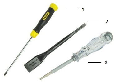
| 1 | Small Phillip's head screwdriver | 2 | Plastic Scribe |
| 3 | Small Flathead screwdriver |
 Note: Be aware that using a large Phillips or Flat Head screwdriver may result in damage to the head of the screws. This would make their removal impossible without speciality tools, that aren't available to our onsite engineers.
-
Pre-Removal Instructions Before removing the System Cover :
-
During installation or removal of any hardware always ensure all data is backed up properly
-
Disconnect any telephone, network, or USB cables from the computer
-
Disconnect the computer and all attached devices from their electrical outlets
-
-
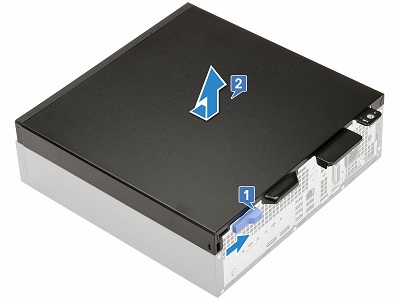
Press the blue release catch on the back of the system in towards the center [1] and then push the top cover towards the rear of the chassis and lift it up and off the system [2]
-
Pre-Removal Instructions Before removing the Front Bezel :
-
During installation or removal of any hardware always ensure all data is backed up properly
-
Disconnect any telephone, network, or USB cables from the computer
-
Disconnect the computer and all attached devices from their electrical outlets
-
Please remove the System Cover
-
-
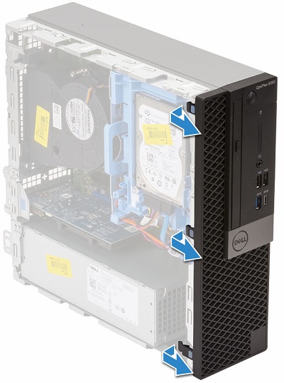
Pry up the three (3) retention clips along the top of the bezel
-
Rotate the bezel on the hooks at the bottom of the bezel and pull it off the front of the PC
-
Pre-Removal Instructions Before removing the Expansion Cards :
-
During installation or removal of any hardware always ensure all data is backed up properly
-
Disconnect any telephone, network, or USB cables from the computer
-
Disconnect the computer and all attached devices from their electrical outlets
-
Please remove the System Cover
-
-
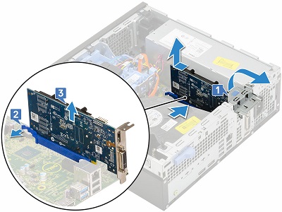
Pull the blue metal tab at the rear of the system to unlock the option slots [1]
-
Check for a release tab [2] press it if there and lift the card up and out of the slot and PC [3]
-
Pre-Removal Instructions Before removing the Coin Cell Battery :
-
During installation or removal of any hardware always ensure all data is backed up properly
-
Disconnect any telephone, network, or USB cables from the computer
-
Disconnect the computer and all attached devices from their electrical outlets
-
Please remove the System Cover
-
-
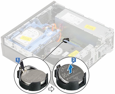
The coin cell battery is located between the heatsink and the PSU, using a plastic scribe press the release latch until the battery pops out [1]
-
Remove the battery from the system [2]
-
Pre-Removal Instructions Before removing the Hard Disk Drive (HDD) :
-
During installation or removal of any hardware always ensure all data is backed up properly
-
Disconnect any telephone, network, or USB cables from the computer
-
Disconnect the computer and all attached devices from their electrical outlets
-
Please remove the System Cover
-
-
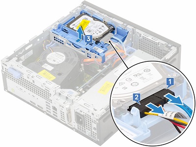
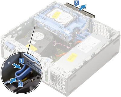
The HDD is located in the front right corner of the system. Both 3.5" and 2.5" HDD's fit in this assembly. Disconnect the cables at the rear of the drive [1,2]
-
Push the blue release table at the rear of the assembly and lift towards the front of the system and lift the assembly out of the PC [3]
-
Pre-Removal Instructions Before removing the Optical Disc Drive (DVD/CD RW) :
-
During installation or removal of any hardware always ensure all data is backed up properly
-
Disconnect any telephone, network, or USB cables from the computer
-
Disconnect the computer and all attached devices from their electrical outlets
-
Please remove the System Cover, Front Bezel and HDD Assembly
-
-
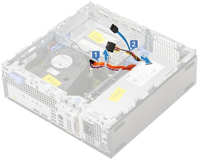
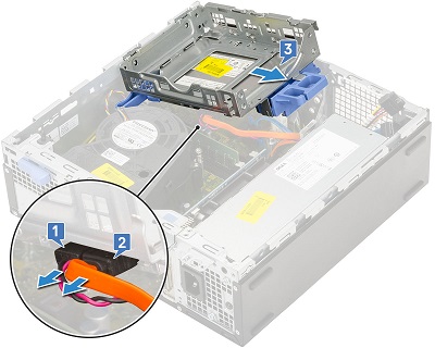
Unroute the ODD cables [1] and HDD cables [2] from the retention clip and HDD-ODD release tab on the right-hand side of the drive cage.
-
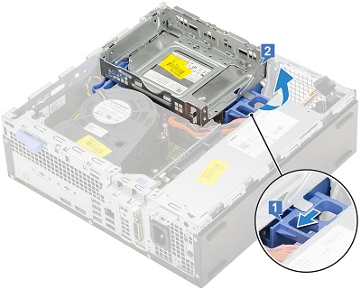
Push the blue slide towards the rear of the PC [1] to unlock the drive cage. Rotate the cage up over the right-hand side of the chassis [2]
-
Disconnect the ODD power and data cables [1,2] from the back of the ODD and slide and lift the drive cage out of the system [3]
-
Squeeze the blue release tab at the back of the ODD together [1] and push the latch towards the front of the drive cage [2] and pull the ODD away from the drive cage [3]
-
Pre-Removal Instructions Before removing the M.2 SSD Card :
-
During installation or removal of any hardware always ensure all data is backed up properly
-
Disconnect any telephone, network, or USB cables from the computer
-
Disconnect the computer and all attached devices from their electrical outlets
-
Please remove the System Cover, Front Bezel and Drive Cage
-
-
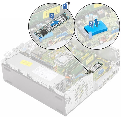
The M.2 is located under the drive cage, remove the screw holding the card down [1]
-
Lift the card out of the connector and PC [2] and remove the thermal pad from underneath the card [3]
-
Pre-Removal Instructions Before removing the Heatsink Blower Fan:
-
During installation or removal of any hardware always ensure all data is backed up properly
-
Disconnect any telephone, network, or USB cables from the computer
-
Disconnect the computer and all attached devices from their electrical outlets
-
Please remove the System Cover, Front Bezel and Drive Cage
-
-
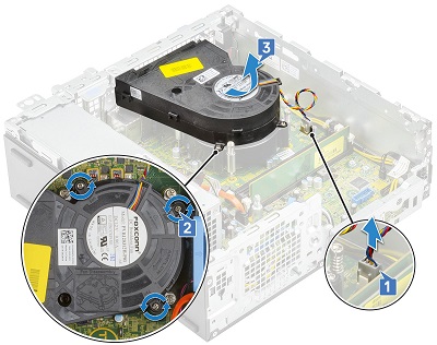
Disconnect the fan cable at the motherboard [1] and remove the three (3) screws holding the blower to the heatsink [2]
-
Lift the heatsink fan away from the computer [3]
-
Pre-Removal Instructions Before removing the Memory :
-
During installation or removal of any hardware always ensure all data is backed up properly
-
Disconnect any telephone, network, or USB cables from the computer
-
Disconnect the computer and all attached devices from their electrical outlets
-
Please remove the System Cover, Front Bezel and Drive Cage
-
-
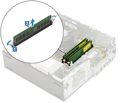
The memory is located between the heatsink and front of the PC, pull the tabs on either side of the memory dimm apart [1]
-
When the memory pops up, lift it up and out of the PC [2]
 Note: Repeat steps 2 and 3 for any additional memory dimms in the system.
-
Pre-Removal Instructions Before removing the Internal Speakers :
-
During installation or removal of any hardware always ensure all data is backed up properly
-
Disconnect any telephone, network, or USB cables from the computer
-
Disconnect the computer and all attached devices from their electrical outlets
-
Please remove the System Cover, Front Bezel and Drive Cage
-
-
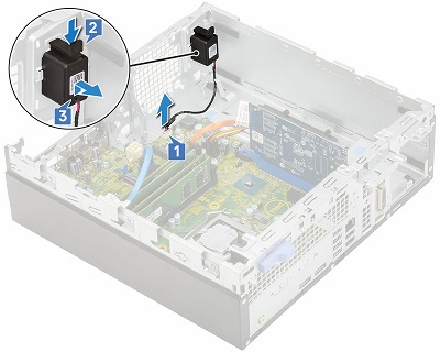
The speaker is located in front of the PSU. Disconnect the speaker cable from the motherboard [1]
-
Press the release tab on top of the speaker assembly [2] and lift the assembly up and off of the chassis [3]
-
Pre-Removal Instructions Before removing the Power Supply Unit (PSU) :
-
During installation or removal of any hardware always ensure all data is backed up properly
-
Disconnect any telephone, network, or USB cables from the computer
-
Disconnect the computer and all attached devices from their electrical outlets
-
Please remove the System Cover, Front Bezel and Drive Cage
-
-
Disconnect the Square power connector from the rear right corner of the system [1] and un-route the cable from around the chassis [2]

-
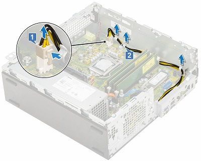
Remove the three (3) screws securing the PSU from the rear of the PC [1] and disconnect the power connector from the motherboard in front of the memory [2] and lift the power cables away from the system [3]
-
Press the blue release tab in front of the PSU [4] and the PSU towards the front of the PC and lift it out of the system [5]
| If you require further assistance, please contact Technical Support. | |
| Contact Us | Go back to the OptiPlex 5070 teardown contents page |