
Unsolved

1 Rookie

 • 

11 Posts

 • 

33 Points

151

June 18th, 2026 08:01

Dell dss 2500

I want to customize my server with basic server components and without a server chassis. 

I have these things in stock:-

1) Dell DSS 2500 motherboard

2) 2 x intel xeon e5-2650v4

3) 8 x 32 GB ECC RAM

4) 2 x 2 TB HDD SATA

5) 2 x Dell 450-watt power supply

6) 2 x Dell 750-watt power supply

7) 6 x server fan

I have connected the following things to the server, but when I start it, it gets stuck at the BIOS. Please check the photo or video.

1) Dell DSS 2500 motherboard

2) 2 x intel xeon e5-2650v4

3) 8 x 32 GB ECC RAM

4) 2 x 2 TB HDD SATA

5) 2 x Dell 450-watt power supply

6) 6 x server fan

7) Connected both HDD Sata drives with onboard raid controller card with wire  { mini SAS (SFF-8087) TO 4X SATA forward break out cable }

I have questions to ask:-

1) What are the basic components required to run an operating system?

2) Do I require IDrac 8 physical card, front control panel, back panel, raiser card and HDD back panel
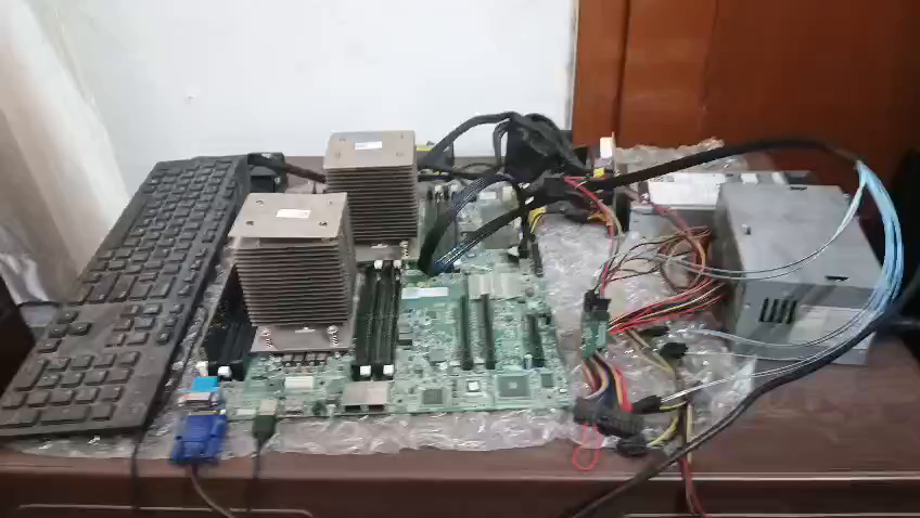

1 Attachment

Moderator

 • 

3.8K Posts

 • 

25.4K Points

June 22nd, 2026 06:45

Hi,

Basic Components Required to Run an Operating System
To successfully boot into an operating system (OS) without a factory enclosure, your open-air motherboard setup must include:
  • Motherboard (Dell DSS 2500 System Board)
  • Processor (CPU) with attached heat sink
  • Memory (RAM) (At least one validated ECC DIMM module)
  • Power Supply Unit (PSU) connected to the 24-pin and CPU power rails
  • Storage Device (HDD, SSD, or USB drive loaded with an installer/OS)
  • Cooling System (A continuous RPM signal fed into the master fan headers)
  • Video/Display Output (Monitored via the onboard VGA port)
Step-by-Step Diagnostic Check
  1. Reduce down to Minimal POST: Pull out 7 of your 8 RAM sticks. Leave only one 32GB module in slot A1. Disconnect the Mini-SAS breakout cable entirely from the board to rule out drive handshake errors. 
  2. Upgrade Power Input: Install your 2 x 750W power supplies instead of the 450W versions. 
  3. Verify Master Fans: Make sure your server fans are populated starting directly from header FAN1 sequentially. 
  4. Clear NVRAM/CMOS: Locate the NVRAM_CLR jumper on the board, move the plastic block over to pins 2-3 for 10 seconds, and return it back to pins 1-2 to wipe out any stale chassis configuration history. 
  5. Boot to Menu: Turn the unit on and continuously tap F2 (to enter BIOS Settings) or F12 (to enter Boot Diagnostics) to see if you can bypass the splash freeze. 
If you can tell me which exact text or error code is displayed on the screen when it freezes, or what color the onboard status LEDs are blinking, I can pinpoint the exact trace error causing the system halt. 

1 Rookie

 • 

11 Posts

 • 

33 Points

June 22nd, 2026 11:25

@Dell-Martin S​ 

Hi,

I have done these steps 1,2, 4, and 5, but the same issue.

For step 3, I can't find the header, FAN1 but I can see fan2, fan3, fan4, fan5, and fan6 headers on the motherboard. Please help me to find the header fan1

I want to give more information. I have not connected the IDRAC8, the back panel ( backpanel where hdd/ ssd attached), control panel ( where the power button is), no hdd/ssd attached.Keyboard not working, no light on keyboard ( keyboard connected to usb port and checked on both usb ports)

I want to use an on-board RAID controller.

ABOUT ERRORS

1) No error shows on the monitor 

2) If you see the video. When I power on from the mains. It automatically starts. On the monitor, I can see the memory configuration done. After that, the monitor turned off, and then the amber light started blinking. When I push the button, the blue light blinks, and vice versa.

1 Attachment

(edited)

Moderator

 • 

3.8K Posts

 • 

25.4K Points

June 22nd, 2026 11:58

On this specific enterprise platform, Fan 1 and Fan 2 are combined into a single proprietary multi-pin fan connection block or are directly fed through the front chassis control power lanes.


To run an open-air unsupported motherboard configuration with an onboard RAID controller, you must emulate the missing chassis components.
 
1. Trick the Front Control Power Rails
Because you lack the physical power button control panel assembly, you must trick the main front panel header.
  • Locate the multi-pin Front Panel header on the edge of the board.
  • Look for the Power Button Pin Pair (typically documented near the corner of the pins, or traceable via standard Dell 24-pin breakout rules).
  • Use a physical jumper block or briefly bridge the power pins with a screwdriver to toggle the state cleanly, rather than letting the board auto-boot from a raw power rail surge.
 
2. Install a Chassis Intrusion Jumper 
Look closely at the board for a small 2-pin header labeled INTRUSION.
  • When left completely open, the BIOS assumes the server lid is off and will freeze before allowing an operating system to boot.
  • Place a standard plastic jumper block over these two pins to "close" the circuit. This signals to the BIOS that the chassis is secure. [1]
 
3. Re-route Your Fans
Since you cannot populate a dedicated physical FAN1 header, plug your 6 server fans directly into headers FAN2, FAN3, FAN4, FAN5, and FAN6. If you have a 6th fan leftover, you will need to utilize a split trailing harness or an active fan hub to replicate the RPM pulse width modulation (PWM) signal across all channels so the BMC does not flag a missing fan zone. 
 
4. Isolate the Onboard RAID Controller
Since you are planning to use the onboard RAID controller without a drive backplane, make sure your Mini-SAS to 4x SATA forward breakout cable is connected to the primary onboard SAS port (often labeled SATA_A or SAS_A). Do not connect any drives yet. First focus on forcing the motherboard to stay powered on with a live USB keyboard light.
 
good luck

1 Rookie

 • 

11 Posts

 • 

33 Points

June 22nd, 2026 15:29

@Dell-Martin S​ 

Hi,

For step 2

1) I can't find the pin or the connector.

2) But I find this connector. What is this connector used for? On it, it's written J_RAVAJE

     Please see photo

1 Attachment

1 Rookie

 • 

11 Posts

 • 

33 Points

June 22nd, 2026 16:05

Sorry, mistype. Not J_RAVAJE, Its J_RAVAGE 

1 Rookie

 • 

11 Posts

 • 

33 Points

June 22nd, 2026 16:26

Is it possible to check logs or errors through BMC?

Moderator

 • 

3.8K Posts

 • 

25.4K Points

June 23rd, 2026 06:29

1)

Because the DSS 2500 is an enterprise node motherboard built for high-density datacenters, standard two-pin pinouts are replaced with multi-pin functional blocks:
  1. Location: The actual Chassis Intrusion line is bundled directly inside the Front Control Panel Header (the long double-row pin grid on the front edge of the board) or routed through one of the vertical riser slot pins. [1]
  2. The Problem: Because you have no front control panel assembly plugged in, the intrusion detection pins are sitting entirely disconnected. The BIOS reads an empty connection as an open chassis lid, causing the system to halt immediately.


2) 

The connector labeled J_RAVAGE is a proprietary engineering header used during factory production. It breaks out the motherboard's SPI / I2C bus lines directly to the BMC / iDRAC chip. Dell technicians use it with specialized hardware program clips to manually re-flash corrupted firmware or read underlying board log traces.
This connector cannot help you bypass the chassis intrusion or boot issues. Leaving it empty is perfectly normal and required for consumer use.

Moderator

 • 

3.8K Posts

 • 

25.4K Points

June 23rd, 2026 06:30

That's the problem with unsupported configs

1 Rookie

 • 

11 Posts

 • 

33 Points

June 23rd, 2026 12:43

Hi,

I can't find the Chassis Intrusion line on the Front Control Panel Header. I have attached photos of the front control panel header.

2 Attachments

1 Rookie

 • 

11 Posts

 • 

33 Points

June 23rd, 2026 14:52

Hi,

My mistake. There is an INTRUSION, but without a connector. Please check the photo in the attachment. Should i jumper two pins?

1 Attachment

1 Rookie

 • 

11 Posts

 • 

33 Points

July 3rd, 2026 14:40

@Dell-Martin S​ 

Please check the video for error in control panel.

1 Attachment

1 Rookie

 • 

11 Posts

 • 

33 Points

July 3rd, 2026 16:28

@Dell-Martin S 

Should I require a backplane to run this? 

I connected the onboard RAID controller connector to the SATA hard drive with the cable https://www.amazon.in/GUDMART%C2%AE-SFF-8087-Transmission-22-5Gbit-Bandwidth/dp/B0D9NZTLHZ

No Events found!

Top