Precision 7740 Teardown Removal Guide for Customer Replaceable Units (CRUs)
Summary: This article is a guide to the parts of the Dell Precision 7740 Mobile Workstation that are considered OK for anyone to remove and replace.
Symptoms
These guides take you step by step through the safe removal of the Customer Replaceable Unit (CRU) parts of a Precision 7740 Mobile Workstation system. (CRUs are the parts of the system that should not need an engineer to remove or replace.) The guides include figures that reference what is involved.
Table of Contents:
Removal Guide
If these guides do not cover what you are looking to do, then you want to reference your System Manual.
The article below provides information about safe practices to consider before working with electrical equipment.
Cause
Not applicable
Resolution
Removal Instructions
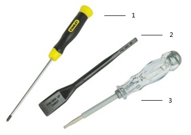
| 1 | Small Phillips head screwdriver | 2 | Plastic Scribe |
| 3 | Small Flat head screwdriver |
-
Pre-removal instructions before removing the battery:
-
During installation or removals of any hardware, always ensure that all data is backed up properly.
-
Disconnect any telephone, network, or USB cables from the computer.
-
Disconnect the computer and all attached devices from their electrical outlets.
-
-
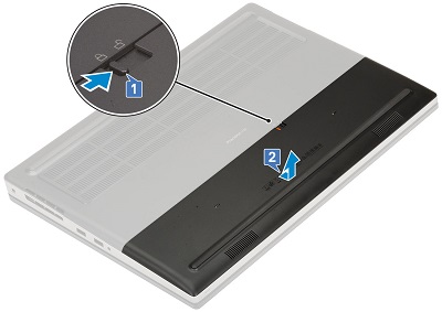
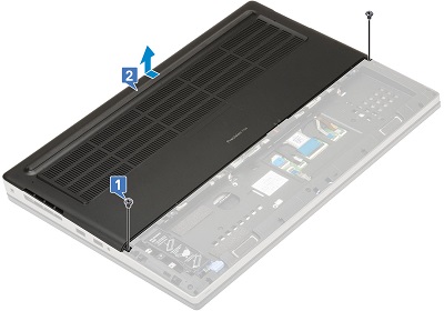
The battery cover takes up the bottom third of the base. Slide the battery latch in the middle of the cover towards the unlock icon [1]. Pull the battery cover away from the rear of the system and lift it off the bottom of the computer [2].
-
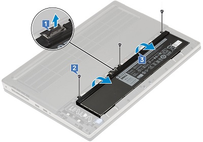
For the 6-Cell Battery, disconnect the battery cable from the connector on the middle of the battery [1]. Remove the three (3) screws along the top edge of the battery [2] and remove the battery away from the system [3].
-
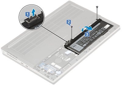
For the 4-Cell Battery, disconnect the battery cable from the connector on the left corner of the battery [1]. Remove the two (2) screws along the top edge of the battery [2] and remove the battery away from the system [3].
-
Pre-removal instructions before removing the access panel:
-
During installation or removals of any hardware, always ensure that all data is backed up properly.
-
Disconnect any telephone, network, or USB cables from the computer.
-
Disconnect the computer and all attached devices from their electrical outlets.
-
Remove the Battery.
-
-
The access panel covers the top two-thirds of the base. Remove the two (2) screws securing the bottom corners of the door [1].
-
Push the door towards the rear of the system and pull it off the system [2].
-
Pre-removal instructions before removing the micro-SD card:
-
During installation or removals of any hardware, always ensure that all data is backed up properly.
-
Disconnect any telephone, network, or USB cables from the computer.
-
Disconnect the computer and all attached devices from their electrical outlets.
-
-
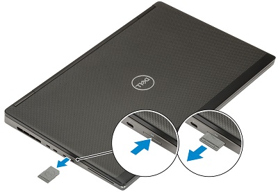
Push the seated micro-SD card further into the reader. It pops out far enough for you to get a grip of it.
-
Pull the micro-SD card fully out of the slot and system.
-
Pre-removal instructions before removing the cellular SIM card:
-
During installation or removals of any hardware, always ensure that all data is backed up properly.
-
Disconnect any telephone, network, or USB cables from the computer.
-
Disconnect the computer and all attached devices from their electrical outlets.
-
Remove the Battery, and System Cover.
-
-
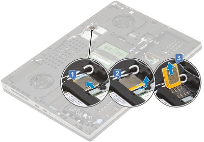
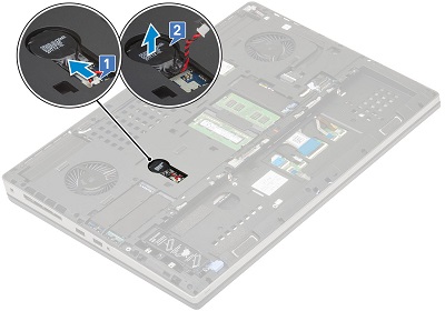
The SIM card is located above the WLAN card, gently slide the SIM card cover towards the rear of the computer to unlock it [1]. (Be careful, the card cover can become fragile.) Flip the SIM card up and over along the top edge of the card [2] and lift the card out of the system [3].
-
Pre-removal instructions before removing the keyboard:
-
During installation or removals of any hardware, always ensure that all data is backed up properly.
-
Disconnect any telephone, network, or USB cables from the computer.
-
Disconnect the computer and all attached devices from their electrical outlets.
-
Remove the Battery, and System Cover.
-
-
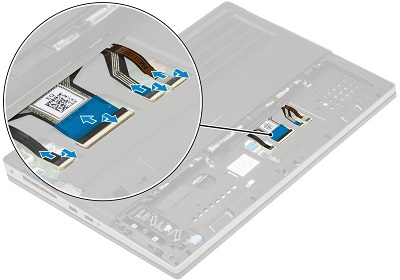
The keyboard's cables are located underneath the battery. Lift the catches on the zif connectors and disconnect the keyboard cable, the fingerprint cable, and the fingerprint button cable from the connectors on the motherboard.
-
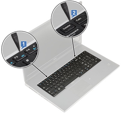
Turn the system over and open it so you can get access to the keyboard lattice. Using a plastic scribe or similar tool pry up the lattice. Start at the recess points between the F3 and F4 keys and the Delete and Calc keys.
-
Lift the lattice up and out of the system.

-
Remove the five (5) screws that hold the keyboard to the palm rest [1]. Pry up the bottom edge of the keyboard and work along both sides [2,3,4].

-
Pull the keyboard toward you and lift it out of the system.

-
Pre-removal instructions before removing the memory:
-
During installation or removals of any hardware, always ensure that all data is backed up properly.
-
Disconnect any telephone, network, or USB cables from the computer.
-
Disconnect the computer and all attached devices from their electrical outlets.
-
Remove the Battery, System Cover, and Keyboard.
-
-
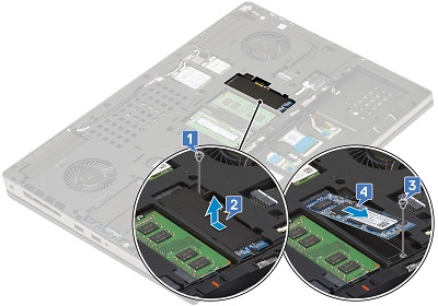
The primary memory is located underneath the keyboard. Remove the single screw securing the memory shield [1] and slide the shield to the left and lift it up away from the memory [2]. Pull the metal retention clips away from the memory DIMM [3] and lift out of the computer [4]. Repeat for any additional memory DIMMs at that location.
-
Turn the system over, because the secondary memory is located in the middle of the base of the system. As with the primary memory, pull apart the metal retention clips on either side of the memory DIMM [1]. Lift it out of the slot [2] and repeat for any additional DIMMs at that location.

-
Pre-removal instructions before removing the hard drive:
-
During installation or removals of any hardware, always ensure that all data is backed up properly.
-
Disconnect any telephone, network, or USB cables from the computer.
-
Disconnect the computer and all attached devices from their electrical outlets.
-
Remove the Battery, and System Cover.
-
-
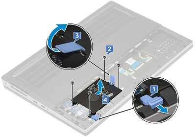
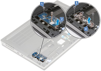
The 2.5" hard drive is located to the left side of the Battery. Pull the blue locking clip at the bottom-left corner of the hard drive cage [1] and remove the four (4) screws from around the cage [2]. Pull up on the release latch on the right side of the cage [3] to lift it up and out of the system [4].
-
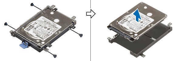
Remove the four (4) screws holding the hard drive in its cage and lift it out of the cage.
-
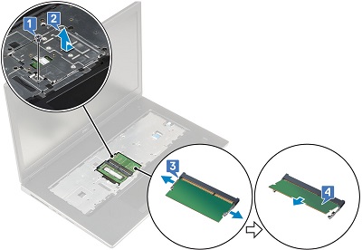
Remove the short screw from the top of the interposer card and the longer screw from the bottom of the card [1]. Pull the card towards the bottom of the system and lift it out of the computer [2].
-
Remove the three (3) screws that secure the card holder to the computer [3] and remove it as well [4].
-
Pre-removal instructions before removing the M.2 Solid State Drive (SSD):
-
During installation or removals of any hardware, always ensure that all data is backed up properly.
-
Disconnect any telephone, network, or USB cables from the computer.
-
Disconnect the computer and all attached devices from their electrical outlets.
-
Remove the Battery, and System Cover.
-
-
There are four (4) possible locations on the base of the system to fit an M.2 SSD card. The steps below take you through where each position is:
-
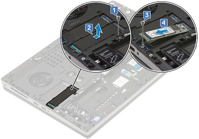
Slot 4 is located in the bottom-left corner of the base. Remove the single screw that holds the module in place [1]. Pull the blue release catch towards the bottom of the system [2]. Lift the module out of the computer [3].

-
To remove the M.2 card from the module, remove the screw from the bottom-left corner of the module [1] and pull off the thermal plate [2]. Remove the screw securing the card to the module [3] and lift the card out of the module [4].

-
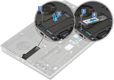
Slot 3 is located above the Battery, bay in the left corner of the base. Remove the single screw that holds the thermal plate [1] in place and pull the plate out of the system [2]. Undo the screw [3] securing the end of the card and lift the card out of the computer [4].
-
Slot 5 is located between Slot 3 and the left corner system fan. Remove the single screw that holds the thermal plate [1] in place and pull the plate out of the system [2]. Undo the screw [3] securing the end of the card and lift the card out of the computer [4].
-
Slot 6 is located between the secondary memory and the right corner system fan. Remove the single screw that holds the thermal plate in place [1]. Remove the plate from the system [2]. Remove the screw securing the card to the system [3] and lift the card out of the computer [4].
-
-
Pre-removal instructions before removing the coin-cell battery:
-
During installation or removals of any hardware, always ensure that all data is backed up properly.
-
Disconnect any telephone, network, or USB cables from the computer.
-
Disconnect the computer and all attached devices from their electrical outlets.
-
Remove the Battery, and System Cover.
-
-
The coin-cell battery is located to the left of the secondary memory. Disconnect the coin cell cable from the motherboard [1].
-
Peel the battery off the adhesive holding it in the system [2].
-
Pre-removal instructions before removing the cellular WWAN wireless card:
-
During installation or removals of any hardware, always ensure that all data is backed up properly.
-
Disconnect any telephone, network, or USB cables from the computer.
-
Disconnect the computer and all attached devices from their electrical outlets.
-
Remove the Battery, and System Cover.
-
-
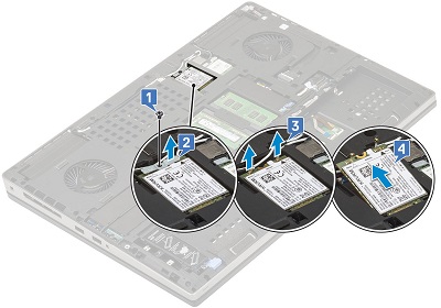
The WWAN card is located above the secondary memory. Remove the screw [1] and the bracket [2] from the card.
-
Disconnect the antenna cables from the card [3]. (The cables have a press-stud connector and pop off the stud with a little pressure.) When the card pops up, lift it out of the connector and the computer [4].
-
Pre-removal instructions before removing the WLAN card (WiFi, Wireless):
-
During installation or removals of any hardware, always ensure that all data is backed up properly.
-
Disconnect any telephone, network, or USB cables from the computer.
-
Disconnect the computer and all attached devices from their electrical outlets.
-
Remove the Battery, and System Cover.
-
-
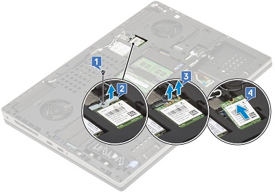
The WLAN card is located between the WWAN card and the right side system fan. Remove the screw [1] and the bracket [2] from the card.
-
Disconnect the antenna cables from the card [3]. (The cables have a press-stud connector and pop off the stud with a little pressure.) When the card pops up, lift it out of the connector and the computer [4].
If you require further assistance, contact Technical Support.
| Contact Us |