PowerScale: Install and Hardware Upgrade Tips for Intel 12800 IB Switch
Summary: This article provides information with regard to correct installation and hardware upgrade procedures for the EMC Intel 12800 Infiniband switches provided with PowerScale Clusters. These switches contain field replaceable units (FRUs) and the number of ports can also be upgraded by the addition of switch leaf modules. ...
This article applies to
This article does not apply to
This article is not tied to any specific product.
Not all product versions are identified in this article.
Instructions
When installing or upgrading the hardware on the Intel 12800 Infiniband (IB) PowerScale Switch, the following tips and guidelines should be reviewed. Please review this entire article before doing any work on an Intel 12800 Infiniband Switch.
For further detailed information, please refer to the Intel-supplied "True Scale Fabric Switches 12000 Series" documentation package. These can be found on the Intel documentation site.
INFORMATION ABOUT POWER SUPPLIES
The number of power supplies required depends on the number of switch ports installed. For each power supply supplied and present in the IB switch, a power cord must be installed in the corresponding power inlet. For the 12800 switches, make certain that the DC ON/OFF switch is illuminated. If it is not, press the button to supply power.
The following guideline should be considered when upgrading and installing the Switch:
Model 12800-040 (up to 96 IB ports): Minimum 2 power supplies required.
Model 12800-120 (up to 288 IB ports): Minimum 3 power supplies required. Power supplies required for AC redundancy = 4.
Example: If you have 97 IB ports, you should consider having 4 active power supplies installed.
If you need more information about power, please consult Appendix A of the TrueScale 12000 Hardware Installation Guide.
INFORMATION ABOUT THE MANAGEMENT MODEL
All True Scale switch models can take a maximum of 2 Management modules. Important to note, is that BEFORE power-up and after install in the customer rack, the following steps must be controlled and completed.
A management module (MM) installed in a 12800 system system normally has a label which protects the mechanical release latch (MRL) switch inside the MM from shock and vibration during shipping. This label must be removed after install in the customer rack and BEFORE power-on (otherwise the management module will not correctly initialize and activate).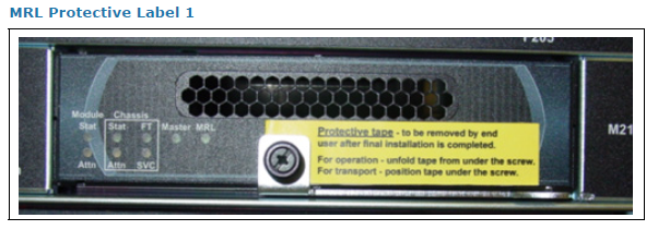
To remove the protective label, do the following:
1. Disengage the thumb screw and partially rotate the lever.
2. Peel off and remove the protective label.
3. Re-engage the lever and tighten the thumb screw. The MRL LED should be GREEN when the MRL thumbscrew is secured to the serial-Ethernet-chassis-EEPROM (SEEB) board, as shown in the image below.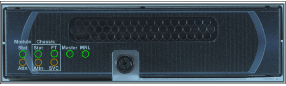
INFORMATION CONSIDERATIONS DURING INSTALLATION AND HARDWARE UPGRADE
FANS
1. It is recommended that the intake fan side is installed towards the cold aisle.
2. It is recommended that the exhaust fan side is installed towards the hot aisle.
Whether or not exhaust fans are present are dependent on the IB switch model.
Model 12800-040 (up to 96 IB ports): 4 Intake and 0 Exhaust fans will be present.
Model 12800-120 (up to 288 IB ports): 5 intake and 3 exhaust fans will be present.
If you need more information about fans, please consult Appendix A of the TrueScale 12000 Hardware Installation Guide.
To determine whether you have an intake or an exhaust fan, consider the following image and information: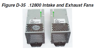
Check the FRU label or note the location of the open notch to determine which fan type you have. Intake Fan = 12800-FITK-9x. Exhaust Fan = 12800-FEXH-9X.
MANAGEMENT MODULE and LEAF RELATIONSHIP
The minimum requirement for each switch is one leaf module per management module. This leaf must be installed in the corresponding management leaf slot. In a dual management module EMC-supplied switch, leaf modules are supplied in management slots L101 and L102.
Power ON the switch ONLY AFTER making sure the MRL is correctly engaged.
LEAF MODULES AND INSTALLATION
18 or 24-port leaf modules are available. Leafs are added from bottom to top, and left to right. Leafs can be added on-line. To install the leaf, remove the supplied protective cover from the switch and simply push the leaf module in place.
In the diagram below, the correct LEAF INSTALLATION process would be to populate Slot 101, then Slot 102, then Slot 103, then Slot 104, and so on, filling the chassis up and then right. Follow this method for leaf installation until all Leaf Modules are installed. In the diagram below, a spine Module is shown in Slot 105.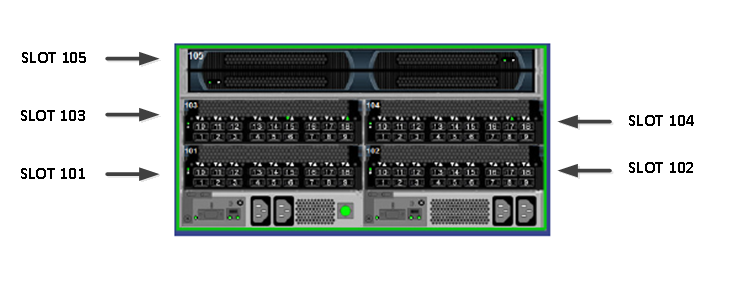
VERIFICATION
It is always recommended to verify that the hardware installation has succeeded. The recommendation is to connect to the Switch Chassis Viewer WEBUI, as follows:
Default IP of Isilon IB Switches: 192.168.100.9
The standard method will be that the on-site Engineer will connect to a RJ-45 Management Port on the Switch Management Module using a standard Cat 5 Ethernet cable.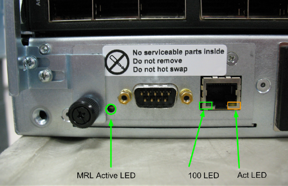
Configure the field laptop for a 192.168.100.99/255.255.240.0 IP Address.
1. Connect to the WEBUI
Open a browser window and connect to IP 192.168.100.9:
User login name: admin
User Password: adminpass
The Chassis Viewer home page is displayed. All modules should be present.
2. Connect via SSH and control Firmware Version
Open PuTTY or your preferred SSH client and connect to IP 192.168.100.9.
User login name: admin
User password: adminpass
switchPrompt> fwVersion
(Verify the customer firmware level.). This should be 7.2.x. If not, follow How to upgrade firmware on Intel (QLogic) 12300 and 12800 InfiniBand switches to update the firmware.
MODULE LED INFORMATION
Below is general LED information. The above-mentioned Hardware Installation Guide provides more details about the LEDs.
Leaf Module LEDs: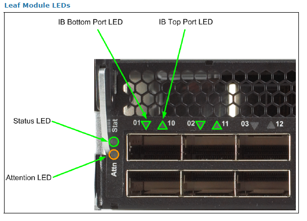
Fan LEds: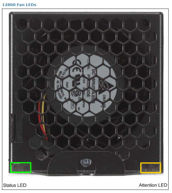
Power Supply LEDs: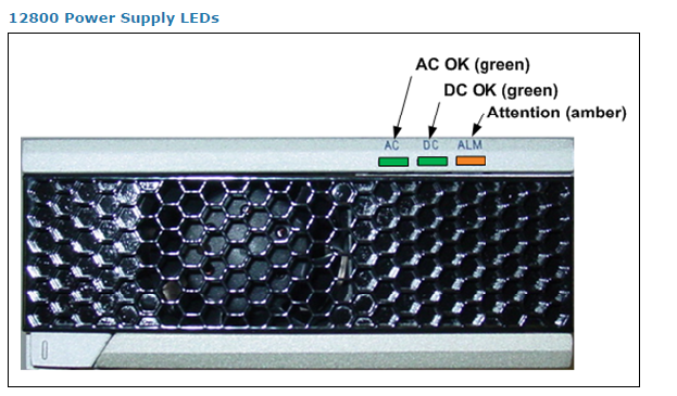
Please open an SR and contact EMC Support if any hardware problems are discovered in the installation or ugprade of any PowerScale IB switch.
Affected Products
Isilon SwitchesProducts
Isilon Switch QLOGIC 48-PORT QDR SWITCH 12800-040, Isilon SwitchesArticle Properties
Article Number: 000019215
Article Type: How To
Last Modified: 08 Jan 2026
Version: 4
Find answers to your questions from other Dell users
Support Services
Check if your device is covered by Support Services.