SmartFabric OS10 Virtual Link Trunking Layer 2 Reference Architecture
Summary: Dell Virtual Link Trunking (VLT) allows Layer 2 information to be shared across the two nodes. For this purpose, the same VLT domain-id should be configured on both VLT nodes. For rapid convergence and optimal service, the same VLT MAC address should be configured on both the nodes using the vlt-mac command (optional). In the absence of vlt-mac configuration, if the primary VLT node goes down, the VLT port channel on the secondary node flaps, causing slight traffic disruption. ...
This article applies to
This article does not apply to
This article is not tied to any specific product.
Not all product versions are identified in this article.
Instructions
Dell Virtual Link Trunking allows Layer-2 information to be shared across the two nodes. For this purpose, the same VLT domain-id should be configured on both VLT nodes. For rapid convergence and optimal service, the same VLT MAC address should be configured on both the nodes using the vlt-mac command (optional). In the absence of vlt-mac configuration, if the primary VLT node goes down, the VLT port channel on the secondary node flaps, causing slight traffic disruption.
Figure 1. Simple Layer 2 VLT
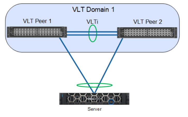
The primary node election's priority is based on the lower system mac-address of the switch; however, with the primary-priority command, the VLT node with the least configured priority takes over as the primary node. This election is not preempted. If the primary node is reloaded, it is assigned as the secondary role. The role change avoids disruptions in traffic flow due to the election process.
The election happens only during the initial configuration or when VLT is initially launched. The VLT role election has no significance for the data traffic flowing through the VLT domain. It is only for the control protocol exchange and handles potential split-control failure scenarios.VLAN ID 4094 is assigned automatically and internally reserved as a control VLAN to exchange VLT-related information between the nodes. The IPv6 address that is automatically assigned within the reserved range is mapped for VLAN 4094 for reachability between the VLT nodes.
For the VLT interconnect (VLTi) link, once the discovery interfaces are configured on both nodes, port channel 1000 is automatically configured, mapping the physical discovery interfaces. The ports should be configured as no switchport from the default Layer-2 mode while configuring the discovery interfaces.
Every thirty seconds, heartbeat messages are sent between the VLT nodes to check the liveliness of the peers and to handle the VLTi failure scenario. The heartbeat interval value is configurable and reaches the peer through the backup destination. Similarly, keep-alive messages (nonconfigurable) are sent through the VLTi port channel.
For VLT port channels, the user should explicitly assign the vlt-port-channel id to the configured port channel on both of the nodes. This port channel identifier should be the same for both of the nodes.
Important factors to remember:
VLTport channel interfaces must be switch ports.- Dell Technologies strongly recommends that the VLT interconnect (
VLTi) be a staticLAGand that you disableLACPon theVLTi. - If you include RSTP or PVST, it must be configured before
VLTis configured. VLTHeartbeat is supported only on default VRFs.- If you enable
IGMPsnooping on theVLTpeers, ensure the value of thedelay-restorecommand is not less than the query interval. - Ensure that the spanning tree root bridge is at the Aggregation layer.
VLTinterconnect over 1G ports is not supported.- Each
VLTdomain has a unique MAC address that you create. - In a
VLTdomain, the peer switches must run the same Dell Networking OS software version. - If you replace a
VLTpeer node, preconfigure the switch with theVLTsystem MAC address,unit-id, and otherVLTparameters before connecting it to the existingVLTpeer switch using theVLTiconnection.
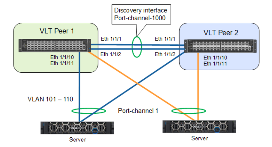
In this sample configuration, the 1/1/1 and 1/1/2 interfaces form the discovery interface/VLTi (Po-1000) on the VLT Peer1. Similarly, the 1/1/1 and 1/1/2 interfaces form the discovery interface on VLT Peer2. The VLT backup destination is mapped to the remote peer's management IP address. Port channel 1 is configured on both VLT nodes as interface 1/1/10 and 1/1/11. VLAN 101-110 is mapped to port channel 1.
Figure 2. Sample configuration
The configurations for VLT-Peer1 and VLT-Peer2 are the same except for the back-up destination IP address. The sample configuration for VLT-Peer1 is as follows:
VLT-Peer1# configure terminal
VLT-Peer1(config)# interface ethernet 1/1/1
VLT-Peer1(conf-if-eth1/1/1)# no shutdown
VLT-Peer1(conf-if-eth1/1/1)# no switchport
VLT-Peer1(conf-if-eth1/1/1)# exit
VLT-Peer1(config)# interface ethernet 1/1/2
VLT-Peer1(conf-if-eth1/1/2)# no shutdown
VLT-Peer1(conf-if-eth1/1/2)# no switchport
VLT-Peer1(conf-if-eth1/1/2)#exit
VLT-Peer1(config)# vlt-domain 1
VLT-Peer1(conf-vlt-1)# primary-priority 1
VLT-Peer1(conf-vlt-1)# vlt-mac de:11:de:11:de:11
VLT-Peer1(conf-vlt-1)# discovery-interface ethernet 1/1/1
VLT-Peer1(conf-vlt-1)# discovery-interface ethernet 1/1/2
VLT-Peer1(conf-vlt-1)# backup destination 10.16.208.184
VLT-Peer1(config)# interface range vlan 101-110
VLT-Peer1(conf-range-vl-101-110)#exit
VLT-Peer1(config)# interface port-channel 1
VLT-Peer1(conf-if-po-1)# switchport mode trunk
VLT-Peer1(conf-if-po-1)# switchport trunk allowed vlan 101-110
VLT-Peer1(conf-if-po-1)#end
Additional Information
For a full guide, see Dell SmartFabric OS10 - Virtual Link Trunking - Reference Architecture Guide | Dell Technologies Info Hub
Affected Products
PowerFlex rack, ScaleIOArticle Properties
Article Number: 000317732
Article Type: How To
Last Modified: 27 Jan 2026
Version: 3
Find answers to your questions from other Dell users
Support Services
Check if your device is covered by Support Services.