PowerStore: Node Embedded Module LEDs
Summary: This article covers the PowerStore major component LED states, locations, descriptions, and more. Understanding the LED states is critical for troubleshooting.
This article applies to
This article does not apply to
This article is not tied to any specific product.
Not all product versions are identified in this article.
Symptoms
This article covers the PowerStore major component LED states, locations, descriptions, and more. Understanding the LED states is critical for troubleshooting.
Table of Contents
- Before you Begin
- Base Enclosure Front View
- Base Enclosure Rear View
- Embedded Module View
- Base Enclosure I/O Module View
- Base Enclosure Power Supply
- 2U, 25-drive Expansion Enclosure Front View
- 2U, 25-drive Expansion Enclosure Rear View
- 2U, 25-drive Expansion Enclosure Power Supply, and Cooling Module
1. Before Starting
- This article uses details from the PowerStore Hardware Information Guide.
- Each Node contains one embedded module that can hold one 4-port card for frontend connectivity and internal communication between nodes and appliances.
- This article includes a diagram from Node A (bottom node). Node B has the same LED indicator structure, however it is inverted as the Node is installed upside down in the Enclosure.
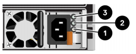
2. Base Enclosure Front View
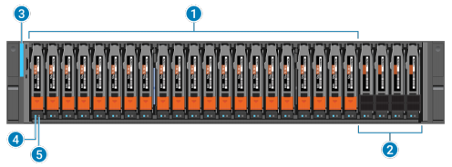
The front of the base enclosure contains the following elements:
| Location | Description |
|---|---|
| 1 | Drives |
| 2 | NVRAM NVMe drives (Note: In configurations that only use two NVMe NVRAM drives, slots 21 and 22 must remain empty.) |
| 3 | Base enclosure power-on LED |
| 4 | Drive power and activity LED |
| 5 | Drive fault LED |
Table 1: Base Enclosure Front View
Base enclosure and drive LEDs: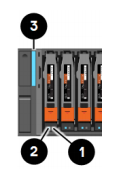
| LED | Location | State | Description |
|---|---|---|---|
| Drive fault | 1 | Amber | Fault has occurred. |
| Off | No fault has occurred. | ||
| Drive Activity | 2 | Blue | Drive activity. |
| Off | The drive is powered off. | ||
| Base enclosure power and fault | 3 | Blue | Power is on. No fault has occurred. |
| Amber | Power is on. Fault has occurred within the enclosure. | ||
| Blue and amber alternating | The system is not initialized. | ||
| Off | The power is off. |
Table 2: Base Enclosure and Drive LEDs
3. Base Enclosure Back View
- The rear of the base enclosure contains two nodes: NodeA and NodeB.
- Each Node contains the following hardware components:
- One embedded module
- Two optional I/O modules
- One power supply module

| Location | Description |
|---|---|
| 1 | Node B |
| 2 | Node A |
| 3 | Power supply module |
| 4 | I/O module, slots 0 and 1 |
| 5 | Embedded module |
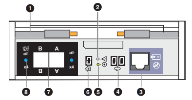
4. Embedded Module View
- Each node contains one embedded module that can hold one 4-port card for frontend connectivity and internal communication between nodes and appliances.
- The first two ports of the 4-port card on the embedded module connect to a 10GbE/25GbE Ethernet switch.
- Note: Both nodes must have the same type of embedded modules in the same slots.
- The embedded module contains the following components:
- One 4-port card
- One non-maskable interrupt (NMI) button
- Two mini-SAS HD backend ports
- Two RJ45 LAN connectors
- System management Port
- Service Port
- One USB port
- One mini serial port
- One DB9 serial port
Embedded module and 4-port card LED status:
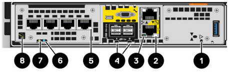
Embedded module LEDs:
| LED | Location | State | Description |
|---|---|---|---|
| Embedded module power | 1 | Amber | Embedded module has faulted. |
| Off | No fault has occurred, normal operation. | ||
| Ethernet port link | 2 | Green | Link established. |
| Off | No link established | ||
| Ethernet port activity | 3 | Amber blinking | Port activity. |
| Off | No port activity | ||
| SAS port link | 4 | Blue | SAS port link is up. |
| Off | No link established | ||
| Port link | 5 | Green | Link up with high speed. |
| Amber | Link up with degraded speed. | ||
| Off | Link down | ||
| Node Fault | 6 | Amber | Fault has occurred. |
| Blue | Node in Degraded Mode | ||
| Amber or blue blinking | The system is booting. | ||
| Blue and amber alternating (blue for 3 seconds) | The system is not initialized. A management IP address has not been assigned. | ||
| Blue and amber alternating at one second intervals. | Node is in Service Mode | ||
| Off | No fault has occurred. normal operation. | ||
| Node Power | 7 | Green | Node is no (main power). |
| Green blinking | Node is initializing a serial over LAN session (Standby Mode). | ||
| Off | Node is off. | ||
| Unsafe to remove | 8 | White | Do not remove the node. Improper removal could cause data loss. |
| Off | Safe to remove the embedded module when the embedded module has been properly prepared. |
NOTE: For further information see these articles:
5. Base Enclosure I/O Module View
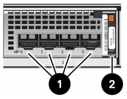
The example above is an Ethernet module.
| LED | Location | State | Description |
|---|---|---|---|
| Port Link | 1 | Green or blue | Link up |
| Off | Link down | ||
| Power fault | 2 | Green | Power on |
| Amber | Power fault |
Table 5: Base Enclosure I/O Module View
6. Base Enclosure Power Supply
- Each node of the base enclosure contains a power supply.
- If a power supply fails on a node, the other power supply maintains the power for the entire appliance.
Base enclosure power supply LEDs:
| LED | Location | State | Description |
|---|---|---|---|
| Fault | 1 | Solid amber | Power supply or backup fault. check cable connection. |
| Off | No fault | ||
| DC power (output) - Not Supported | 2 | Green | N/A |
| Off | N/A | ||
| AC power (input) | 3 | Green | AC power is on. |
| Off | AC power is off. Verify the power source. |
7. 2U, 25-drive Expansion Enclosure Front View
The front of the 2U, 25-drive expansion enclosure includes the following components:
- Drives in 2.5-inch carriers (hot-swappable)
- Status LEDs

| Location | Description |
|---|---|
| 1 | 2.5 inch, 12-Gb/s SAS drives |
| 2 | Expansion enclosure fault LED (amber) |
| 3 | Expansion enclosure power status LED (blue) |
| 4 | Drive status and activity (blue) |
| 5 | Drive fault LED (amber) |
2U, 25-drive Expansion Enclosure, and Drive Status LEDs:
| LED | Location | Color | State | Description |
|---|---|---|---|---|
| Expansion enclosure fault | 2 | Blue | On | No fault |
| Amber | On | Fault | ||
| Expansion enclosure power | 3 | Blue | On | Powering up and powered up |
| — | Off | Powered down | ||
| Drive Fault | 4 | Amber | On | Fault |
| — | Off | No fault | ||
| Drive power and activity | 5 | Blue | On | Powering up and powered up |
| Blinking | Drive activity |
8. 2U, 25-drive Expansion Enclosure Rear View
The rear of the 2U, 25-drive expansion enclosure includes the following components: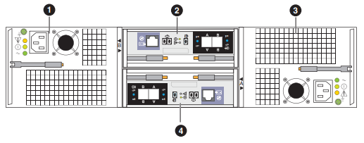
| Location | Description |
|---|---|
| 1 | Power supply and cooling module (B) |
| 2 | 12-Gb/s SAS link control card (LCC) (B) |
| 3 | Power supply and cooling module (A) |
| 4 | 12-Gb/s SAS link control card (LCC) (A) |
2U, 25-drive Expansion Enclosure LCC ports, LEDs, and connectors:
2U, 25-drive Expansion Enclosure LCC Component Locations:
| Location | Description |
|---|---|
| 1 | Ejector latch handles |
| 2 | LCC fault LED |
| 3 | LCC management port (RJ-12) (not used) |
| 4 | Backend bus ID display (always displays 01). |
| 5 | LCC power LED |
| 6 | Enclosure ID display |
| 7 | 12-Gb/s SAS ports |
| 8 | SAS port status LED |
12-Gb/s LCC LED Status:
| LED | Location | Color | State | Description |
|---|---|---|---|---|
| LCC fault LED | 2 | Amber | On | Fault within the LCC |
| — | Off | No fault or powered off | ||
| LCC power LED | 5 | Green | On | Powered on and no fault |
| — | Off | Powered off | ||
| SAS port status LED | 8 | Amber | On | SAS port faulted |
| Blue | On | SAS port linked up | ||
| — | Off | No connector in port |
9. 2U, 25-drive Expansion Enclosure Power Supply, and Cooling Module
The following figure shows an example of a 2U, 25-drive expansion enclosure power supply, cooling module and status LEDs: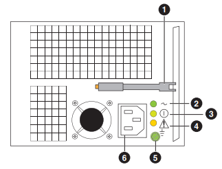
| Location | Description |
|---|---|
| 1 | Ejector latch handle |
| 2 | AC power LED (input) |
| 3 | DC power LED (input) - (not supported) |
| 4 | Power supply and cooling module fault LED |
| 5 | Ground screw |
| 6 | Power supply AC power in |
2U, 25-drive Expansion Enclosure Power Supply, and Cooling Module LED status:
| LED | Location | Color | State | Description |
|---|---|---|---|---|
| AC power LED (input) | 2 | Green | On | AC power on |
| — | Off | AC power off, verify source power. | ||
| DC power LED (output) | 3 | Green | On | DC power on (not supported) |
| — | Off | DC power off, verify source power. | ||
| Power supply and cooling module fault LED | 4 | Amber | On | Fault |
| Blinking | During power shutdown and during overvoltage (OVP) and under undervoltage protection (UVP) fault | |||
| — | Off | No fault or power off |
Cause
This article covers the PowerStore major component LED states, locations, descriptions, and more.
Resolution
This knowledge article may be used to learn helpful PowerStore LED information. Each Node contains one embedded module that can hold one 4-port card for frontend connectivity and internal communication between nodes and appliances.
Note: Node B has the same LED indicator structure, however it is inverted as the Node is installed upside down in the Enclosure.
Affected Products
PowerStoreArticle Properties
Article Number: 000125739
Article Type: Solution
Last Modified: 14 Mar 2025
Version: 7
Find answers to your questions from other Dell users
Support Services
Check if your device is covered by Support Services.