PowerEdge: Understanding Disk Errors: PDR1001, PDR3, and LED Indicators on Physical Drives (PD)
Summary: This article explains what disk errors PDR1001 and PDR3 mean on Dell PowerEdge servers, how physical drive LED indicators provide quick visual diagnostics, and the best practices to resolve these issues. By understanding these alerts and acting promptly, you can maintain storage health, prevent downtime, and protect critical data. ...
This article applies to
This article does not apply to
This article is not tied to any specific product.
Not all product versions are identified in this article.
Instructions
Managing enterprise storage health is critical for uptime and data integrity. Dell PowerEdge servers provide advanced monitoring through iDRAC and RAID controllers, which report disk-related issues using error codes such as PDR1001 and PDR3. Additionally, physical drive LEDs offer quick visual diagnostics. This article explains what these codes mean, why they occur, and how to respond effectively.
1. What is PDR1001?
PDR1001 signals a physical disk failure:
- Message: Fault detected on drive
<number>in disk drive bay<bay>. - Cause: The RAID controller has detected a failure and taken the disk offline.
- Impact: The affected drive is no longer part of the array, which can lead to degraded performance or data loss if redundancy is compromised.
Recommended Actions
- Reseat the drive to rule out connection issues.
- Check iDRAC logs for related alerts.
- Update firmware for the RAID controller and drives.
- If the error persists, contact Dell Support.
2. What is PDR3?
PDR3 indicates a physical disk malfunction:
- Message: The Physical Drive (PD)
<PD name>is not correctly functioning. - Common Causes:
- Firmware bugs (notably on certain Intel SSDs).
- Hardware failure or connectivity issues.
- Backplane or RAID controller voltage anomalies.
Recommended Actions
- Reseat the disk and verify detection.
- Update firmware (especially for affected SSD models).
- If unresolved, contact Dell Support.
- For repeated PDR3 alerts, inspect the backplane and controller.
3. Understanding Physical Drive LED Indicators
On hot swap drives, the backplane provides two LED indicators per drive that transmit light to the top of their respective caddies.
- The drive manages the light on the left and indicates activity on the drive.
- The backplane with the storage controller controls the indicator on the right and is used to indicate drive status.
Refer to the sections below for detailed explanations:
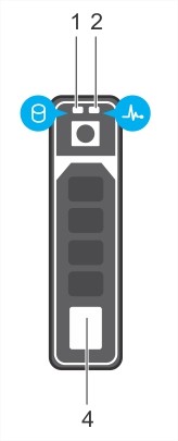 |
1. Physical disk activity indicator 2. Physical disk status indicator 4. Physical disk eject button. |
| Drive-status indicator pattern (RAID only) | Condition |
| Blinks green two times per second | Identifying the drive or preparing for removal. |
| Blinks green, amber, and turns off. | Predicted drive failure. |
| Blinks amber four times per second | Drive failure |
| Blinks green slowly | Drive rebuilding |
| Steady green | Drive online |
| Blinks green three seconds, amber three seconds, and turns off six seconds. | Rebuild aborted. |
| Off | Ready for insertion, removal, or not detected |
Affected Products
PowerFlex rack, Modular Infrastructure, Rack Servers, Tower Servers, XE Servers, XR Servers, OEM Server Solutions, PowerEdge c6300, PowerEdge C6400, PowerEdge C6600Article Properties
Article Number: 000143247
Article Type: How To
Last Modified: 04 Dec 2025
Version: 8
Find answers to your questions from other Dell users
Support Services
Check if your device is covered by Support Services.