Dell PowerEdge MX Deployment with VMware Cloud Foundation Deployment Guide
Notes, cautions, and warnings
Audience and Scope
Audience and Scope
This deployment guide includes step-by-step instructions for deployment of VMware Cloud Foundation on Dell PowerEdge MX platform. Any deviation from the listed configurations may negatively impact functionality.
- Dell products including the location of buttons, cables, and components in the hardware
- Functional knowledge of the items in the Dell owner's manuals for the products being used
- VMware products and the components or features of vSphere
- Data center infrastructure best practices in the areas of server, storage, networking, and environmental considerations such as power and cooling
The scope of this document excludes existing infrastructure components outside of the specific hardware and software that is mentioned in this guide. Dell takes no responsibility for any issues that may be caused to existing infrastructure during deployment.
Overview
Overview
Dell Technologies vision
VMware Cloud Foundation
Deployment of VMware Cloud Foundation on the Dell PowerEdge MX platform provides a hyperconverged infrastructure solution incorporating best-in-class hardware from Dell with core VMware products including vSphere, vSAN, NSX-T, vRealize Log Insight, and SDDC Manager. Virtualization of compute, storage, and networking is delivered in a single package with VMware Cloud Foundation on the PowerEdge MX7000 chassis.
Dell has determined the compatibility and established certification across hardware and software. The combination of Cloud Foundation software on the PowerEdge MX7000 chassis that is described in this document has been validated by Dell and certified by VMware . The PowerEdge MX platform systems that are described in this guide are certified as vSAN Ready Nodes, as shown in the VMware Compatibility Guide (VCG).
Dell Technologies Demo Center
The Dell Technologies Demo Center is a highly scalable, cloud-based service that provides 24/7 self-service access to virtual labs, hardware labs, and interactive product simulations. Several interactive demos are available on the Demo Center for PowerEdge MX platform deployments. Go to Dell Technologies Interactive Demo: OpenManage Enterprise Modular for MX solution management to quickly become familiar with deploying MX Networks.
Hardware Overview
Hardware Overview
Dell PowerEdge MX7000 chassis
Key features of PowerEdge MX7000 chassis include:
- 7U modular enclosure with eight slots that can accommodate 2S single or four 4S double-width compute sleds and 12 Gb/s single-width storage sleds.
- 25 Gb Ethernet, 12 Gb SAS, and 32 Gb Fiber channel I/O options.
- Three I/O network fabrics—two for general use and one for storage only; each with redundant modules.
- Multichassis networking up to 10 chassis.
- Single management point for compute, storage, and networking.
- High-speed technology connections, now and into the future, with no mid-plane upgrade.
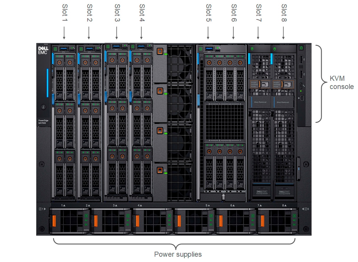
Front view of the Dell PowerEdge MX7000 chassis
- Four PowerEdge MX740c sleds in slots one through four
- One PowerEdge MX840C sled in slots five and six (not used in this guide)
- Two PowerEdge MX5016s sleds in slots seven and eight
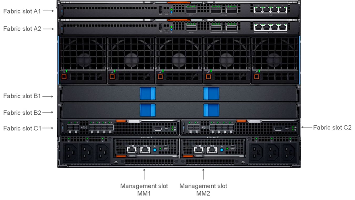
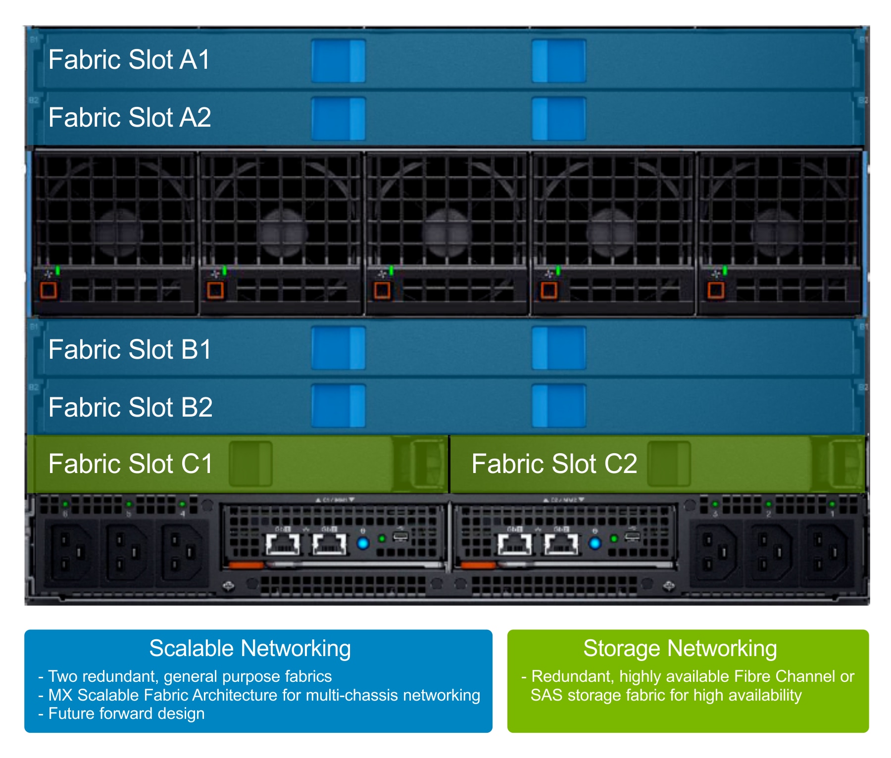
Back view of the Dell PowerEdge MX7000 chassis
- Two Networking MX5108n Ethernet switches installed in fabric slots A1 and A2
- Two PowerEdge MX9002m management modules that are installed in management slots MM1 and MM2
- Two PowerEdge MX5000s SAS fabric switch modules that are installed in fabric slots C1 and C2
- Empty or available fabric slots B1 and B2
Logical view of the Dell PowerEdge MX7000 chassis
Dell PowerEdge MX7000 chassis supports three fabrics: two for general use and one for storage only. All three fabrics support redundant modules.
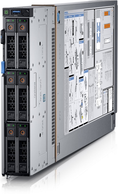
Dell PowerEdge MX740c and MX750c compute sled
The Dell PowerEdge MX740c and MX750c are two-socket, full-height, single-width compute sleds that offer impressive performance and scalability. The MX740c and MX750c are ideal for dense virtualization environments and can serve as a foundation for collaborative workloads. An MX7000 chassis can support up to eight MX740c and MX750c sleds. Mixing compute sleds of different generations is supported.
Key features include:
- Single-width slot design
- One or two CPU sockets
- 24 or 32 DIMM slots of DDR4 memory (MX740c and MX750c)
- Boot options include BOSS-S1 or Internal Dual SD Modules (IDSDM)
- Up to six SAS/SATA SSD/HDD and NVMe PCIe SSDs
- Two PCIe mezzanine card slots for connecting to network Fabric A and B
- One PCIe mini-mezzanine card slot for connecting to storage Fabric C
- iDRAC with Lifecycle Controller
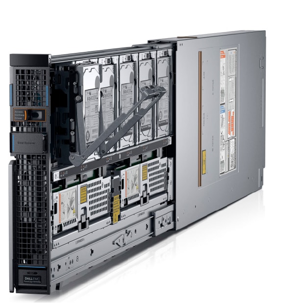
Dell PowerEdge MX5016s storage sled
Dell PowerEdge MX9002m management module
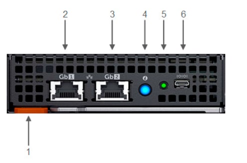
- Handle release
- Gigabit Ethernet port 1
- Gigabit Ethernet port 2
- ID button and health status LED
- Power status LED
- Micro-B USB port
Dell Networking MX9116n Fabric Switching Engine
- Two 100 GbE QSFP28 ports
- Two 100 GbE QSFP28 unified ports
- Twelve 2x100 GbE QSFP28-Double Density (DD) ports
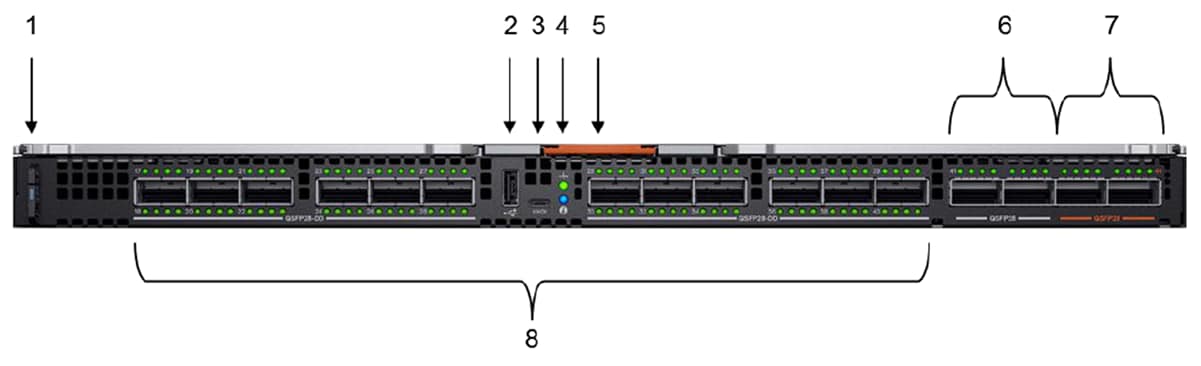
- Express service tag
- Storage USB port
- Micro-B USB console port
- Power and indicator LEDs
- Handle release
- Two QSFP28 ports
- Two QSFP28 unified ports
- 12 QSFP28-DD ports
Dell Networking MX7116n Fabric Expander Module
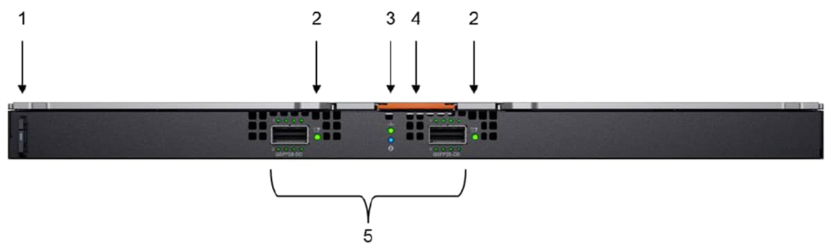
- Express service tag
- Supported optic LED
- Power and indicator LEDs
- Module insertion or removal latch
- Two QSFP28-DD fabric expander ports
Dell Networking MX5108n Ethernet switch
- One 40 GbE QSFP+ port
- Two 100 GbE QSFP28 ports
- Four 10 GbE RJ45 BASE-T ports
The ports can be used to provide a combination of network uplinks, VLT interconnects (VLTi), or for FCoE connectivity. The MX5108n switch supports FCoE Initialization Protocol (FIP) Snooping Bridge (FSB) mode but does not support NPG or direct attach FC capabilities. The PowerEdge MX7000 chassis supports up to four MX5106n Ethernet switches in Fabric A or Fabric B, or both.
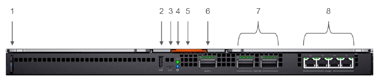
- Express service tag
- Storage USB port
- Micro-B USB console port
- Power and indicator LEDs
- Module insertion or removal latch
- One QSFP+ port
- Two QSFP28 ports
- Four 10GBASE-T ports
Dell PowerEdge MX5000s SAS switch
PowerEdge MX5000s provides Fabric C SAS connectivity to each compute and one or more PowerEdge MX5016s storage sleds. Compute sleds connect to the PowerEdge MX5000s using either SAS Host Bus Adapters (HBA) or a PowerEdge RAID Controller (PERC) in the mini-mezzanine PCIe slot.
The PowerEdge MX5000s switches are deployed as redundant pairs to offer multiple SAS paths to the individual SAS disk drives. The PowerEdge MX7000 chassis supports redundant PowerEdge MX5000s in Fabric C.
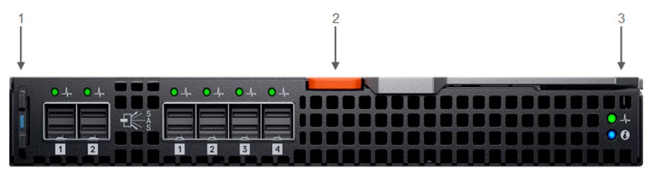
- Express service tag
- Module insertion or removal latch
- Power and indicator LEDs
Dell PowerSwitch S5232F-ON
The Dell PowerSwitch S5232F-ON is a 1U, multilayer switch with 32x 100 GbE QSFP28 ports and 2x 10 GbE SFP+ ports. This guide uses two S5232F-ON switches as leaf switches.

Validated Components
VMware no longer maintains a VMware Compatibility Guide for Cloud Foundation. Since vSAN is an underlying requirement of Cloud Foundation, any hardware specified as a vSAN Ready Node is approved for Cloud Foundation.
Hardware components
- Identical drive configurations in each target host
- There must be one size for all cache drives, as well as one size for all capacity drives
- The number of capacity drives in a host is cleanly divisible by the number of cache drives (that is, the result is a whole number)
- Open the VMware Compatablity Guide in any web browser.
- Select vSAN for What are you looking for" and type MX740c for Keyword.
- Click Update and View Results.
The options listed are all vSAN Ready Nodes based on MX740c.
Software and firmware
The VMware Compatibility Guide (VCG) is the system of record for versions of certain types of firmware and drivers which are certified to be compatible with vSphere and vSAN. These include server platform, vSAN disk controllers, and network interface cards. For more information on other components, see https://www.dell.com/support.
Software
This document is written for VMware Cloud Foundation 4.0 running on ESXi 7.0. The required build and version of ESXi is specified by the version of Cloud Foundation to be installed. It is critical that the versions of both Cloud Foundation and ESXi correspond.
| Software component | Version | Build number |
| Cloud Builder VM | 4.3.1 | 18624509 |
| SDDC Manager | 4.3.1 | 18624509 |
| vCenter Server Appliance | 7.0 Update 2d | 18455184 |
| ESXi | 7.0 Update 2c | 18426014 |
Physical Layout
Physical Layout
You can implement multiple configurations of VMware Cloud Foundation on a Dell PowerEdge MX7000 chassis. The Cloud Foundation software addresses the host servers using their IP address. Deploying compute sleds across multiple PowerEdge MX7000 chassis has no impact on the software as long as the networking is configured properly on the PowerEdge MX I/O Modules (IOMs) and the switches to which the PowerEdge MX7000 chassis connects. The physical layout and resulting cabling is impacted by the number of PowerEdge MX7000 chassis in use, but no other changes are made in the environment.
Configuration options
The Dell PowerEdge MX7000 chassis can be deployed as a single chassis or in a multi-chassis group, enabling multiple chassis to be managed as if they were a single chassis. A PowerEdge MX Scalable Fabric enables multiple chassis to behave like a single chassis from a networking perspective. To learn more about the PowerEdge MX Scalable Fabric Architecture, refer to the Dell EMC PowerEdge MX Networking Deployment Guide.
The PowerEdge MX I/O Guide includes detailed information on Scalable Fabric topologies and the cabling options for all configuration options.
Dual chassis cabling
This section provides details on the topology used in the validation of the deployment for VMware Cloud Foundation in this guide.
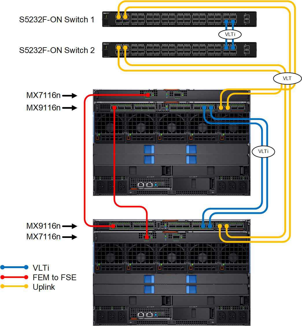
Dell PowerEdge MX5016s storage sleds are internally cabled and the PowerEdge MX5000s SAS IOM has no impact on external cabling.Cabling for a dual Dell PowerEdge MX7000 enclosure configuration using Dell MX9116n Fabric Switching Engines and MX7116n Fabric Expander Modules
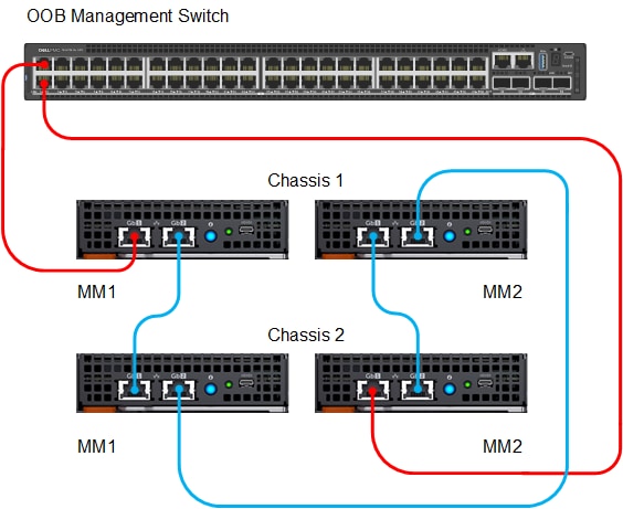
The following diagram shows the management module cabling for a dual chassis deployment. The MX7000 chassis are daisy-chained, and the management modules are pictured without the full chassis.
The following diagram shows the cabling for a dual chassis deployment with uplinks to a customer network leaf switch pair.
Pre-deployment Requirements
Management host
In this example, a host in an existing vSphere environment is used to run the services that are required to install Cloud Foundation. The management VLAN and VXLAN VLAN are extended to this management host. An NTP time server is installed on the management VLAN and a DHCP server on the VXLAN VLAN.
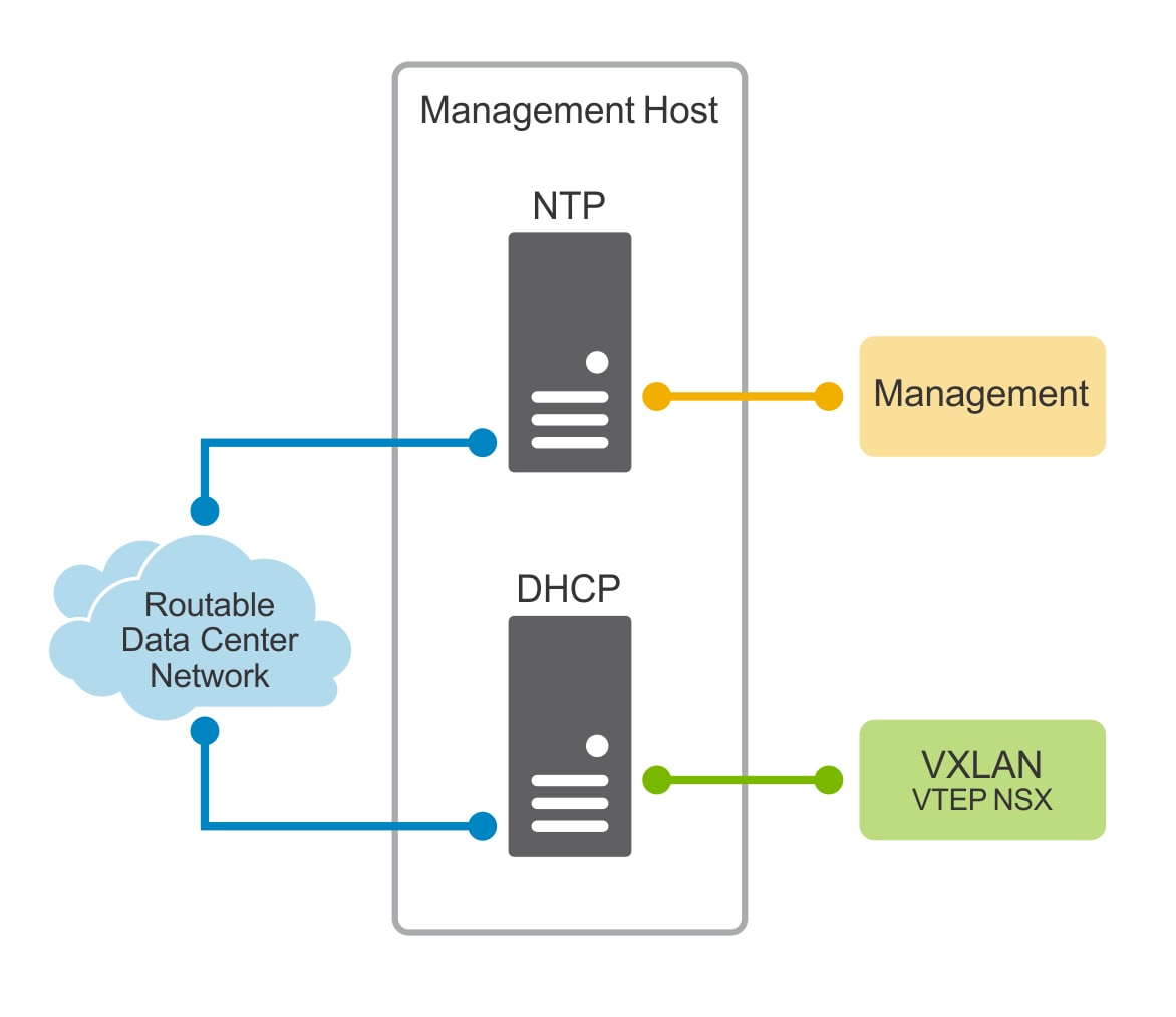
Connectivity
The VMware Cloud Builder VM must be able to communicate with the hosts that become the Cloud Foundation management cluster. In this example, the new cluster hosts were given IP addresses on the 172.17.11.0/24 subnet and placed on the management VLAN (1711). A port group on the management host that was tagged with VLAN 1711 was created and connected to a port on a switch that accepted (ingress) traffic. The switchports between that initial ingress port and the new hosts were tagged with VLAN 1711.
Network services
There are three network services that are essential for VMware Cloud Foundation deployment.
Domain Name System
Domain Name System (DNS) is required to provide both forward and reverse name resolution. The IP addresses of name servers, search domains, and hostnames of all the VMware Cloud Foundation VMs must be inserted into the Cloud Builder deployment parameter sheet. Forward and reverse DNS entries of any hostname that are indicated in the parameter sheet should be tested and retested for both forward and reverse lookups. Test the DNS entries using their Fully Qualified Domain Name (FQDN) and their short name (hostname).
Dynamic Host Configuration Protocol
A VTEP (VxLAN Tunnel End Point) is the software-based endpoint of a VXLAN connection that communicates over IP. The IP addresses can be provided via an IP address pool defined in the VMware Cloud Builder parameter file or via Dynamic Host Configuration Protocol (DHCP). Whenever a new cluster node is added to Cloud Foundation, a new tunnel endpoint is created which requires an IP address.
If DHCP is selected, place the DHCP server (or VM) on a reliable and well-maintained part of your infrastructure. The validation process checks to ensure that an IP address pool is being provisioned or that a DHCP server is available on the VXLAN network as specified in the parameter sheet. Validation fails if no IP address pool is provisioned or there is no DHCP response on the VXLAN network.
Network Time Protocol
Time synchronization is critical to the VMware Cloud Foundation stack. All hosts and the Cloud Builder VM are synchronized to a reference time source before attempting to run the validation phase of the Cloud Builder process. Network Time Protocol (NTP) traffic is routed from client to source or it can travel over the same L2 network.
Networking Requirements
This chapter covers the networking requirements from both the Cloud Foundation software perspective and from a networking hardware connectivity perspective. This section also describes the options for configuring networks on a Dell PowerEdge MX7000 chassis, with a focus on the unique capabilities of the MX7000 SmartFabric and Scalable Fabric infrastructure. The actual networking configuration procedures are described in the later sections.
VMware Cloud Foundation networking
Cloud Foundation requires seven networks and at least one connection to a customer network (for external access to your Cloud Foundation stack). In the following example, a private IP address range is used for all connectivity within the management stack. There is also an IP network that connects back to an external network.
Each of these networks is propagated to the Cloud Foundation stack using tagged VLANs. Using tagged VLANs enables mapping of port groups to VLANs, allowing access to resources as needed. All of these networks are routable to and from each other. The routing task is executed at some layer above the access level switched fabric that is deployed here.
The networks required to deploy Cloud Foundation are listed in the following table:
| Network | Description |
| Management | Dedicated to communication between all the deployed resources and services. When the SDDC Manager Utility needs to communicate to any other service or resource, it uses the management network. |
| vSAN | Used to communicate and synchronize vSAN storage traffic across multiple hosts to ensure data integrity and resiliency. |
| vMotion | Used to quickly redistribute virtual machine state and or storage between hosts. |
| Host Overlay | The host overlay network is used by NSX-T for control plane communication between the hosts of the Cloud Foundation cluster. |
| Uplinks (two) | The uplink networks are used by NSX-T for data traffic into and out of the cluster. |
| Edge Overlay | This network is used by the Edge Nodes in an NSX-T environment to allow the transport nodes to access the capabilities of NSX-T. |
Design considerations
VMware Cloud Foundation consists of a virtual management infrastructure designed to make the deployment of vSAN clusters and resources easier and more consistent. The Dell MX7000 chassis is a compute, storage and networking platform designed to make hardware deployment easier and more consistent.
A component of the MX7000 chassis infrastructure is SmartFabric. SmartFabric is integrated into the OS10 switch operating system and the Dell OME-Modular management software. SmartFabric provides the ability to manage the IOMs running OS10. SmartFabric provides a graphical utility for managing networks and uplinks and customizable templates. Templates are used to configure the server facing ports quickly and consistently on many switch ports. Templates are useful when deploying multiple cluster nodes which would all have the same network requirements. Templates provide value by programmatically identifying the switch ports to which a selected server is connected and configuring those ports based on the selected template. Server profiles are a combination of template and identity settings that are applied to a specific server or multiple servers. When the server template is deployed successfully, OME-M automatically creates and applies a server profile to that template. OME-M also allows you to manually create a server profile that you can apply to the designated compute sleds. Instead of deleting and recreating server templates, profiles can be used to deploy with modified attributes on server templates. A single profile can be applied to multiple server templates with modified attributes, or all attributes.
- Uplink creation and configuration
- VLT
- LACP link aggregation
- Spanning Tree configuration
- VLAN tagging (tagged and untagged)
- VLAN creation
- Server facing port configuration
SmartFabric does not provide capabilities such as Layer 3 routing configurations. Layer 3 routing is an important topic in the VCF deployment conversation. NSX-T, which is deployed as part of VCF, works best when it can exchange routing information with an upstream BGP-enabled router.
The MX7000 Scalable Fabric Architecture leverages the MX9116n Fabric Switching Engine (FSE) and the MX7116n Fabric Expansion Modules (FEM). In this design the Ethernet ports are configured on the FSE and the FEMs extend those ports to their compute resources. A single FSE can support up to nine FEMs and each FEM can connect to as many as eight hosts. Configuration of these server facing ports is implemented by the templates. SmartFabric tracks the ports to which a server is connected and applies the settings defined in a template. The implementation of a template can even track the location of a server if it is moved and dynamically configure the connected switch ports when the server is inserted into a different slot in the same multi chassis group connected to the same scalable fabric.
It is these advantages that have driven the decision to implement SmartFabric mode rather than a manually configured network environment. While manually configured IOMs provide more granular configuration capabilities, SmartFabric provides manageability, portability and scalability that match the manageability and rapid deployment capabilities of Cloud Foundation.
The following figure shows the connectivity between the data center and the MX7000 chassis. The leaf switches are manually configured to connect to a scalable fabric that can contain up to 160 server facing ports. The connection between the top of rack switches and the SmartFabric is a layer 2 connection configured as either an LACP aggregated connection or a Spanning Tree managed connection. VLT is used by SmartFabric to create a robust path when an LACP aggregated connection is deployed.
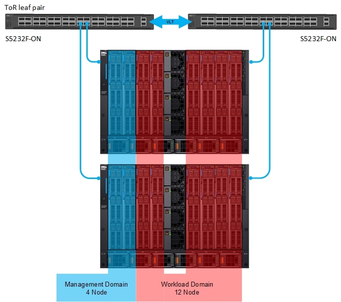
In this example the leaf switches are BGP-enabled, layer 3 devices. While the leaf switches are configured manually, they need only be configured once with minor modifications as the environment expands. The SmartFabric managed IOMs connect to the leaf switches. SmartFabric templates are used to assign network profiles to the assigned servers. Templates can be assigned to follow a specific server that may get moved from one slot to another or from one chassis to another (all chassis and slots must belong to the scalable fabric).
Using this architecture allows expansion of an 8-node cluster to a 16-node cluster by reusing the template used to deploy the first eight nodes. Templates can be cloned, and the cloned templates can be modified and saved as new templates. Using templates to deploy hosts provides fast deployment and consistent results.
Physical hardware
Installing physical hardware to provide additional network interfaces in an MX7000 chassis environment requires the installation of devices into the B fabric of the MX7000 chassis. More MX9116n IOMs are installed into slots B1 and B2 on the rear of the chassis. Extra network mezzanine cards are installed into the B connector of each of MX740c compute sleds to interface with the B fabric IOMs.
Installing dedicated hardware provides better throughput, lower latency, and simplified monitoring of network performance and metrics.
Network connectivity
Deploying Dell Networking MX9116n Fabric Switching Engines (FSEs) and Networking MX7116n Fabric Expansion Modules (FEMs) is a different process. The FSEs are installed into the A1 fabric of the first chassis and the A2 fabric of the second chassis. The FEMs are distributed across both PowerEdge MX7000 chassis in the remaining A fabric slots. The FEMs connect back to the FSEs using a double data rate, 200 Gbps cable. The connection between the compute sleds and the MX modular switches do not use any kind of link aggregation protocol. Additional PowerEdge MX7000 chassis (up to 8 more) can be added and require only the MX7116n FEMs in the A1 and A2 fabric slots. The additional ports available for uplink make the MX9116n an excellent choice for the deployment of VMware NSX-T edge nodes. Since NSX-T is now a part of Cloud Foundation 4.0, we place the emphasis of this document on the MX9116n Scalable Fabric Architecture.
The connections from the modular switches to the external network are implemented using Virtual Link Trunking (VLT) link aggregation. VLT allows you to create a single LACP-managed link aggregation from the two modular switches to an LACP-managed aggregation in the external network. Use the link aggregation only on the link between the modular switches and the customer network.
VLAN and subnets for networking configuration
| Name | VLAN ID | Subnet | Netmask |
Default gateway |
| Management | 1711 | 172.17.11.0 | 255.255.255.0 | 172.17.11.1 |
| vSAN | 1712 | 172.17.12.0 | 255.255.255.0 | 172.17.12.1 |
| vMotion | 1713 | 172.17.13.0 | 255.255.255.0 | 172.17.13.1 |
| Host Overlay | 1714 | 172.17.14.0 | 255.255.255.0 | 172.17.14.1 |
| Uplink1 | 2711 | 172.27.11.0 | 255.255.255.0 | 172.27.11.1 |
| Uplink2 | 2712 | 172.27.12.0 | 255.255.255.0 | 172.27.12.1 |
| Edge Overlay | 2713 | 172.27.13.0 | 255.255.255.0 | 172.27.13.1 |
MTU settings
Configuring jumbo frames is a best practice for both VMware vMotion and vSAN networks, both of which are core components of Cloud Foundation. All the switch ports on the modular switches and up to the aggregation switches used to connect multiple Dell PowerEdge MX7000 chassis enclosures together must be configured for jumbo frames. It is also recommended to configure jumbo frames on the VXLAN network. The validation phase run as part of the Cloud Foundation installation process tests end-to-end connectivity of all specified devices, but fails if the jumbo frames are not correctly configured.
SmartFabric Network Configuration
The Dell PowerEdge MX9002m management module hosts the OpenManage Enterprise Modular (OME-M) console. Creation and deployment of SmartFabric topologies is facilitated using the OME-Modular console in conjunction with the SmartFabric OS10 network operating system on the MX9116n switch.
SmartFabric is a web-based mechanism to create a reusable networking template that can be applied to a PowerEdge MX7000 chassis, the IOMs (switches) and the compute sleds.
SmartFabric creates and configures the switches based on networking best practices. By selecting the topology, SmartFabric creates the VLT domain and VLTi connections and creates the uplink LACP enabled link aggregations. It assigns VLANs to ports as either tagged or untagged based on the networks that are created by the administrator through the SmartFabric interface.
- Create chassis groups.
- Create the networks to be used in the fabric.
- Select IOMs and create the fabric that are based on the required physical topology.
- Create uplinks from the fabric to the existing network and assign networks to those uplinks.
- Deploy the appropriate server templates to the compute sleds.
To create a SmartFabric using the OME-M console, follow the instructions in the Create the SmartFabric section of the Dell EMC PowerEdge MX Networking Deployment Guide.
Create chassis groups
Chassis groups are defined in OME-M. Before a chassis group can be created, the chassis PowerEdge MX9002m modules must be cabled together.
For details on cabling the management modules for multi-chassis deployments, see the Managing chassis section in the Dell EMC OpenManage Enterprise-Modular Edition for PowerEdge MX7000 Chassis User Guide. Cabling diagrams can also be referenced in the Dell EMC PowerEdge MX Networking Deployment Guide.
For details on creating chassis groups, see the Chassis groups section in the Dell EMC OpenManage Enterprise-Modular Edition for PowerEdge MX7000 Chassis User Guide.
Define networks
Networks or subnets should be defined to meet the VMware Cloud Foundation requirements. The prerequisites to define networks are as follows:
- Create chassis groups
- Cloud Foundation management network
- vMotion network
- vSAN network
- VXLAN network
- Uplink1 network
- Uplink2 network
Create VLANs
See the Dell EMC PowerEdge MX Networking Deployment Guide for instructions on how to create VLANs in OME-M.
In this step, all seven networks documented in the VLAN and subnets for networking configuration are defined in OME-M. These VLANs are later used in defining networks on uplinks, and applied to server profiles and templates.
Create the SmartFabric
- MX9116n Fabric Switching Engine (FSE)
- MX9116n FSE and MX7116n Fabric Expander Module (FEM)
- MX5108n
To create a SmartFabric using the OME-M console, follow the instructions in the Create the SmartFabric section in the SmartFabric Creation chapter of the Dell EMC PowerEdge MX Networking Deployment Guide.
A SmartFabric is a logical entity that consists of a collection of physical resources (such as servers and switches) and logical resources (such as networks, templates, and uplinks). In this step, a single SmartFabric is designed for the deployment.
This example with two chassis uses the design type of two MX9116n FSEs in different chassis.
Configure uplinks
The newly created fabric requires uplinks to connect to the rest of the network. These uplinks are created as a single logical link to the upstream network using the same Virtual Link Trunking (VLT).
To create an Ethernet uplink from the MX9116n Fabric Switching Engines (FSEs) to the S5232F-ON leafs, refer to the Create Ethernet – No Spanning Tree uplink section in the SmartFabric Creation chapter of the Dell EMC PowerEdge MX Networking Deployment Guide.
After creating uplinks, the SmartFabric creates an uplink object and the status of the fabric turns green.
This example defines Ethernet port interfaces on each MX9116n to uplink to a pair of top of rack leaf switches in the data center.
Configure jumbo frames
VMware Cloud Foundation requires jumbo frames on all links.
To configure the MTU size, see the Optional steps > Configure Ethernet ports section in the SmartFabric Creation chapter of the Dell EMC PowerEdge MX Networking Deployment Guide. Set all network interfaces to an MTU value of 9216.
Server templates
A server template contains the parameters that are extracted from a reference server and allows the parameters to be quickly applied to multiple compute sleds. First, create an empty template by copying one from any existing compute sled. Then, modify the template and then apply it to new compute sleds as needed.
Create server template
To create a server template, see the Create a server template section of the Server Deployment chapter in the Dell EMC PowerEdge MX Networking Deployment Guide.
Associate network with server template
The templates that you created must be associated with the networks. VLANs set as tagged or untagged will be applied to the settings of the other compute sleds when the templates are deployed.
To associate the networks with a template, see the Deploy a server template section of the Server Deployment chapter in the Dell EMC PowerEdge MX Networking Deployment Guide.
Deploy server template
Deploy the server templates to apply the settings and parameters to the compute sleds. After a server template deployment, the interfaces on the switch are updated automatically. SmartFabric configures each interface with untagged and tagged VLANs along with associated QoS settings.
To deploy the server template, follow the instructions in the Deploy a server template section of the Server Deployment chapter in the Dell EMC PowerEdge MX Networking Deployment Guide.
Server profiles
A server profile is a combination of template and identity settings that are applied to a specific server or multiple servers. When the server template is deployed successfully, OME-M automatically creates and applies a server profile to that template. OME-M also allows you to manually create a server profile that you can apply to the designated compute sleds. Instead of deleting and recreating server templates, profiles can be used to deploy with modified attributes on server templates. A single profile can be applied to multiple server templates with modified attributes, or all attributes.
Profile deployment
PowerEdge MX environment supports Profiles with OME-M 1.30.00 and later. OME-M creates and automatically assigns a profile once the server template is deployed successfully. If the server template is not deployed, OME–M allows user to create server profiles and apply them to compute sled or slot.
To create and assign a server profile, follow the instructions in the Profile deployment section of the Server Deployment chapter in the Dell EMC PowerEdge MX Networking Deployment Guide.
VMware Cloud Foundation and SDDC Design Considerations
VMware Cloud Foundation relies on a set of key infrastructure services to be made available externally. You must configure these external services before you begin deployment.
External services overview
| Service | Purpose |
| Active Directory (AD) |
(Optional) Provides authentication and authorization.
Note: AD is required if you are deploying vRealize Automation.
|
| Dynamic Host Configuration Protocol (DHCP) | Provides automated IP address allocation for VXLAN Tunnel Endpoints (TEPs) if you choose DHCP. |
| Domain Name Service (DNS) | Provides name resolution for the various components in the solution. |
| Network Time Protocol (NTP) | Synchronizes time between the various components. |
| Simple Message Transfer Protocol (SMTP) | (Optional) Provides method for email alerts. |
| Certificate Authority (CA) |
(Optional) Allows replacement of the initial self-signed certificates that are used by Cloud Foundation.
Note: A CA is required if you are deploying vRealize Automation.
|
Active Directory
VMware Cloud Foundation uses Active Directory (AD) for authentication and authorization to resources. The AD services must be reachable by the components that are connected to the management and vRealize networks.
You must configure user and group accounts in AD before adding them to the SDDC manager and assigning privileges.
Dynamic Host Configuration Protocol
VMware Cloud Foundation can use either Dynamic Host Configuration Protocol (DHCP) or static IP address pools to automatically configure each VM kernel port of an ESXi host that is used as a TEP with an IPv4 address. One DHCP scope must be defined and made available for this purpose.
The DHCP scope or IP address pool that is defined should be large enough to accommodate all of the initial and future servers that are used in the Cloud Foundation solution. Each host requires two IP addresses, one for each TEP configured.
Domain Name System
During deployment, you must provide the DNS domain information to be used to configure the various components. The root DNS domain information is required and, optionally, you can also specify subdomain information.
DNS resolution must be available for all the components that are contained within the VMware Cloud Foundation solution, which includes servers, virtual machines, and any virtual IPs that are used. For more information on the components that are required for DNS resolution before starting a Cloud Foundation deployment, see Host names and IP addresses.
Ensure that both forward and reverse DNS resolutions are functional for each component before deploying Cloud Foundation or creating any workload domains.
Network Time Protocol
All components must be synchronized against a common time provider by using the Network Time Protocol (NTP) on all nodes. Important components of VMware Cloud Foundation, such as vCenter Single Sign-On (SSO), are sensitive to a time drift between distributed components. Synchronized time between the various components also assists with troubleshooting.
- The IP addresses of two NTP sources are provided during the initial deployment.
- The NTP sources must be reachable by all the components in the Cloud Foundation solution.
- Time skew is less than 5 minutes between NTP sources.
Simple Mail Transfer Protocol mail relay (optional)
Certificate Authority (optional)
The components of the SDDC require SSL certificates for secure operation. During deployment, self-signed certificates are used for each of the deployed components. These certificates can be replaced with certificates that are signed by an internal enterprise certificate authority (CA) or by a third-party commercial CA.
If you plan to replace the self-signed certificates, the CA must be able to sign a Certificate Signing Request (CSR) and return the signed certificate. All endpoints within the enterprise must also trust the root CA of the CA.
If you plan to deploy vRealize Automation, a CA is required, and the certificates are required during installation.
Physical network requirements
Before deploying VMware Cloud Foundation, configure the physical network to enable the following features:
- VLAN Tagging (802.1Q)
- Jumbo frames
- A minimum MTU value of 1600 is required, however it is recommended that you set the MTU to 9216.
Network pools
Cloud Foundation uses a construct that is called a network pool to automatically configure VM kernel ports for vSAN, NFS, and vMotion.
Cloud Foundation uses an Internet Protocol Address Management (IPAM) solution to automate the IP configuration of VM kernel ports for vMotion, vSAN, and NFS (depending on the storage type being used).
When a server is added to the inventory of Cloud Foundation, it goes through a process called host commissioning. During this process, the hosts are associated with an existing network pool. When the host is provisioned during the create VI workload domain, add cluster, or add host workflow, it automatically configures the VMkernel ports and allocates IP addresses for vMotion, vSAN, and NFS from the network pool the host was associated with.
You can expand the included IP address range of a network pool at any time, however you cannot modify the other network information. Ensure that you have defined each subnet in the network pool to account for current and future growth in your environment.
VLANs and IP subnets
Network traffic types within VMware Cloud Foundation are isolated from each other by using VLANs. Before deploying your SDDC, you must allocate VLAN IDs and IP subnets for each required traffic type. Configure the VLAN IDs and IP subnets in your network to pass traffic through your network devices. Before you start the Cloud Foundation deployment, verify that the allocated network information is configured and does not conflict with pre-existing services before starting your Cloud Foundation deployment.
- The number of workload domains that are created
- The number of clusters defined
- The optional components that are installed
The following table lists the basic allocation of VLANs and IP subnets for a sample deployment. Use this sample to define the VLANs and IP subnets in your environment.
| Workload domain | Cluster | VLAN function | VLAN ID | Subnet | Gateway |
| Management | Cluster-01 | Management | 1711 | 172.17.11.0/24 | 172.17.11.253 |
| vMotion | 1712 | 172.17.12.0/24 | 172.17.12.253 | ||
| vSAN | 1713 | 172.17.13.0/24 | 172.17.13.253 | ||
| VXLAN (NSX-T VTEP) | 1714 | 172.17.14.0/24 | 172.17.14.253 | ||
| vRealize Suite (optional) | 1715 | 172.17.15.0/24 | 172.17.15.253 | ||
| Uplink 1 | 2711 | 172.27.11.0/24 | 172.27.11.253 | ||
| Uplink 2 | 2712 | 172.27.12.0/24 | 172.27.12.253 |
Host names and IP addresses
Before deploying a VMware Cloud Foundation, or creating or expanding a workload domain, you must define the hostnames and IP addresses for various system components.
Most of the defined hostnames and IP addresses need to exist in DNS and be resolvable, through forward and reverse lookups.
- External services—services that are external to the Cloud Foundation solution and are required for proper operation.
- Virtual infrastructure layer—components that provide for the basic foundation of the Cloud Foundation solution.
- Operations management layer—components used for day-to-day management of the environment, for example, vRealize Operations.
- Cloud management layer—services that use the infrastructure layer resources, for example, vRealize Automation.
Host names and IP addresses for external services
- NTP
- AD
- DNS
- Certificate Authority (CA)
The following table provides sample information for the external services. This example uses a DNS domain called osevcf17.local for illustration purposes. Modify the sample information to conform to the configuration of your site.
| Component group | Hostname | DNS | IP address | Description |
| DNS | z18-infra | z18-inra.hevcflab18.in | 172.17.11.11 | DNS & DHCP |
| NTP | ntp01 | z18-ntp01.hevcflab18.in | 172.17.11.251 | First NTP Server |
| ntp02 | z18-ntp02.hevcflab18.in | 172.17.11.252 | Second NTP server |
Host names and IP addresses for the virtual infrastructure layer
Most of the virtual infrastructure components that are installed by VMware Cloud Foundation require their hostnames and IP addresses to be defined before deployment.
During the initial deployment of Cloud Foundation, the management domain is created and you must define components specific to the management domain before installation.
After the initial deployment, additional workload domains are created and you must define components specific to each additional workload domain.
Planning ahead for the initial deployment and the workload domains to be created avoids delays in deployment.
The following table provides an example of the information for the virtual infrastructure layer using the standard deployment model with a single workload domain. This example uses a DNS domain called osevcf17.local for illustration purposes. Modify the sample information to conform to the configuration of your site.
| Workload domain | Hostname | DNS zone | IP address | Description |
| Management | z18-sddc-manager | z18-sddc-manager.hevcflab18.in | 172.17.11.24 | SDDC Manager |
| z18-vc01 | z18-vc01.hevcflab18.in | 172.17.11.23 | vCenter Instance (vcsa) | |
| z18-m01-nsx01 | z18-m01-nsx01.hevcflab18.in | 172.17.11.26 | NSX-T Management Cluster | |
| z18-m01-nsx01a | z18-m01-nsx01a.hevcflab18.in | 172.17.11.27 | NSX-T Virtual Appliance 1 | |
| z18-m01-nsx01b | z18-m01-nsx01b.hevcflab18.in | 172.17.11.28 | NSX-T Virtual Appliance 2 | |
| z18-m01-nsx01c | z18-m01-nsx01c.hevcflab18.in | 172.17.11.29 | NSX-T Virtual Appliance 3 | |
| vcfz18-host01 | vcfz18-host01.hevcflab18.in | 172.17.11.111 | Management ESXi host 01 | |
| vcfz18-host02 | vcfz18-host02.hevcflab18.in | 172.17.11.112 | Management ESXi host 02 | |
| vcfz18-host03 | vcfz18-host0.hevcflab18.in | 172.17.11.113 | Management ESXi host 03 | |
| vcfz18-host04 | vcfz18-host04.hevcflab18.in | 172.17.11.114 | Management ESXi host 04 |
Deploy VMware ESXi to Cluster Nodes
Only perform the steps listed in this section if the compute sleds were not pre-installed with VMware ESXi 7.0. If the compute sleds have been pre-installed with ESXi 7, proceed to Configure ESXi settings—using DCUI. Below are the steps to install ESXi on each of the Dell PowerEdge MX740c hosts that are part of the management cluster. This guide covers the steps to install ESXi remotely using iDRAC Virtual Console with Virtual Media. In this example, a static IP address is assigned to the management interface of the ESXi hosts, which is required for Cloud Foundation.
Prerequisites
- Dell OME-Modular and iDRAC IP addresses or FQDNs
- OME-Modular and iDRAC credentials
- iDRAC Enterprise license that is applied on all nodes
- Dell -customized ESXi image
- Host names, Management VLAN ID, IP address information
- Credentials for vSphere
- Hostnames added to DNS server
Installation of VMware ESXi
- Install the ESXi 7.0 U2 A05 Dell Customized ESXi image.
- After you deploy the ESXi 7.0 U2 A05 Dell Customized ESXi image, upgrade the ESXi host with the VMware-ESXi-7.0U2c-18426014-depot.zip file to achieve ESXi 7.0 Update 2c build# 18426014. You can download the relevant patches by logging into https://customerconnect.vmware.com/patch/, or you can execute the following command on the ESXi hosts:
esxcli software profile update -p ESXi-7.0U2c-18426014-standard -d https://hostupdate.vmware.com/software/VUM/PRODUCTION/main/vmw-depot-index.xml
Connect to iDRAC and boot installation media
- The virtual console should be in HTML5 mode, which is the default setting.
- The location of the Dell Customized ESXi image (ISO image) file should not be changed during the installation process.
- Using a web browser, go to the Open Manage Enterprise Modular (embedded chassis management) web interface at https://<OME Modular Address>.
- Log in with your credentials.
- From the Devices menu, click Compute.
- Select the required compute node.
- Click Launch Virtual Console, and then enable the support in the pop-up window for each iDRAC device.
Note: When the virtual console is launched for the first time, repeating this step may be necessary due to browser pop-up blocker.
Figure 16. Virtual console preview
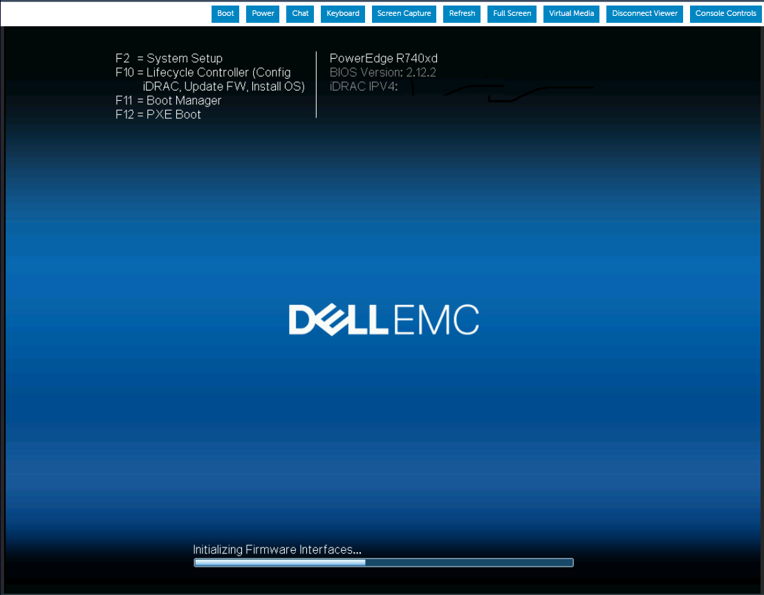
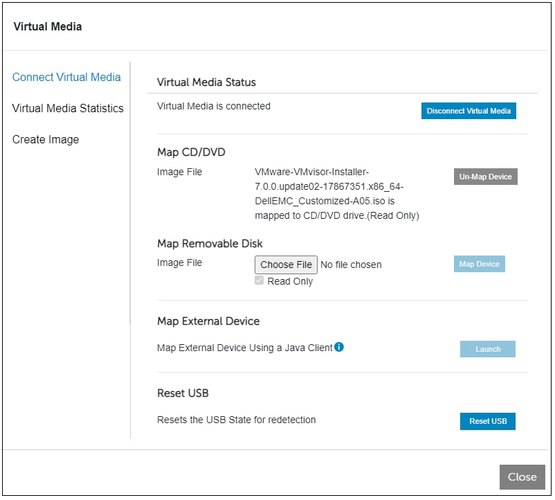
- The mapping screen for the virtual media is displayed on the Virtual Media menu.
- In the Map CD/DVD section, click Choose File.
- Browse and select the required Dell Customized ESXi image (ISO image) file.
- Click Map Device and then click Close.
Figure 17. Virtual media mapping page
- From the Virtual Console menu, click Boot, and then click Virtual CD/DVD/ISO.
- Click Yes.
- From the Power menu, click Power on System.
- If the system is not turned on, click Power on System. If the system is ON, click Power Cycle System (cold boot).
Install VMware ESXi
- In the Welcome to ESXi Installation window, press Enter.
- Review the End User License Agreement (EULA), and then press F11 to accept and continue.
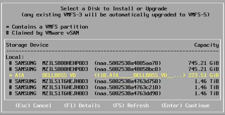
- On the Select a Disk to Install or Upgrade page, select the DELLBOSS VD device, and then press Enter.
Note: If DELLBOSS VD device has been used for previous ESXi installation, in the ESXi/VMFS Found dialog box, choose to overwrite the existing VMFS datastore, and then press Enter.
Figure 18. ESXi disk partition page
- Select the required keyboard layout, and then press Enter.
- Enter the root password, and then press Enter.
- In the Confirm Install window, press F11 to install the VMware ESXi.
- In the Installation Complete window, press Enter to reboot the server.
The installation completes and the server boots into ESXi.
- From the Virtual Media menu, click Disconnect Virtual Media.
Configure VMware ESXi settings using web interface
- Using a web browser, go to the ESXi host-level management web interface at https://<ESXi Host Address>/ui.
- Enter the credentials that were created during the ESXi installation, and then click Log in.
- In the Navigator pane, click Networking.
The current port groups on the host are displayed by default. One is configured with VLAN information that is entered during installation and the other is still at zero.
- Right-click VM Network and then click Edit settings.
Figure 19. ESXi web interface—Edit settings page
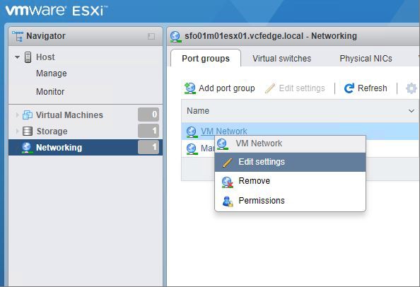
- In the Edit Port Group window, enter the Management VLAN ID, and then click Save.
CAUTION: Leaving the VLAN ID at default setting causes pre-deployment validation to fail during a later step.
- In the Navigator pane, click Manage to set up the NTP.
- In the right pane, click Time & Date.
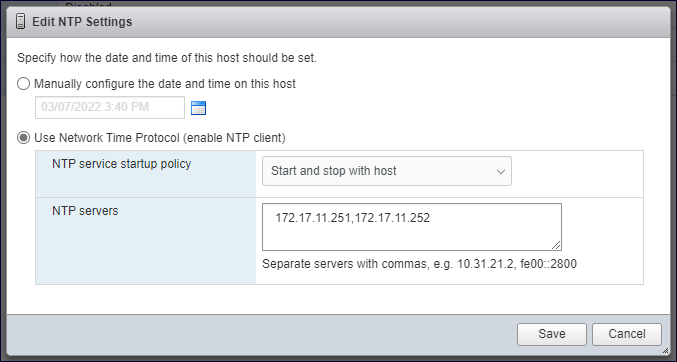
- Click Edit Settings and then select Use Network Time Protocol (enable NTP client).
- In the NTP Servers box, enter the NTP server IP addresses.
Note: If multiple IP addresses are provided, separate the IP addresses with commas.
- Click Save.
Figure 20. ESXi web interface—Edit NTP Settings page
- In the Manage pane, select the Services tab.
The resulting page is shown in the following figure:
Figure 21. ESXi settings web interface—Manage pane
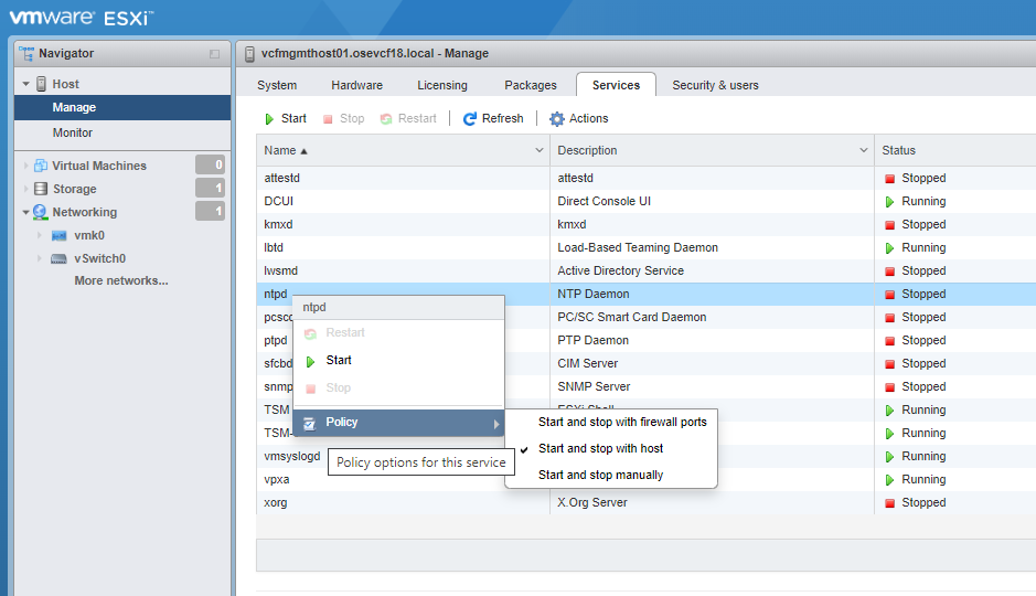
- Right-click on the ntpd service and set the policy to Start and stop with the host.
Repeat all the steps for each host targeted for Cloud Foundation management domain deployment. Validate that each ESXi host can access the NTP servers by establishing an SSH connection to each host and executing the ntpq -p command. A refid value of .INIT. indicates that your host is not obtaining time from your specified time source.
VMware Cloud Builder and SDDC Deployment
The primary software installation tool for VMware Cloud Foundation 4.x is Cloud Builder. It is delivered as a virtual appliance in the standard OVA format. This section describes the steps to deploy the OVA. The Cloud Builder VM is a temporary tool to facilitate deployment of Cloud Foundation. It can be discarded after the deployment.
Deploy VMware Cloud Builder
- Cloud Builder OVA file with version and build numbers that are specified in Validated Components section
- The following must be deployed to an ESXi host outside of the Cloud Foundation target nodes and have network access to the Cloud Foundation Management VLAN on which the Cloud Builder VM resides
- All prior sections are reviewed and any listed steps completed
- Using a web browser, go to the vCenter web interface at https://<vCenter Address>.
- In the Navigator pane, on the Hosts and Clusters tab, locate an available ESXi host.
- Right-click the ESXi host and select Deploy OVF Template.
- Locate the OVA file locally or from the URL, and then click Next.
- Select the required ESXi server to host the Cloud Builder VM, and then click Next.
Note: The selected EXSi server should not be targeted for Cloud Foundation deployment.
- Click Next.
- Review the EULA, and if you agree, click Accept, and then click Next to continue.
- Select the required datastore and then click Next.
- Select the required network and then click Next.
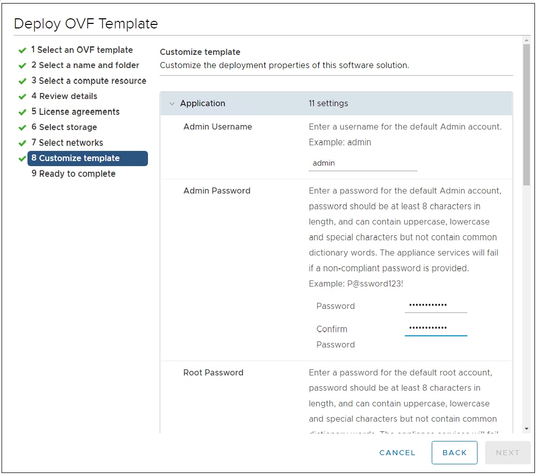
- In the Customize Template page, enter username, password, network IP address and subnet mask, default gateway, hostname, DNS, and NTP resources in the appropriate fields, and then click Next.
CAUTION: You must adhere to the following password rules that are listed on the screen:
- Noncompliant passwords cause an unrecoverable error when attempting to access and use the Cloud Builder VM in the next section of the document.
- The password rules vary for different user accounts. For example, minimum 8-character rule is applicable to some users and minimum 12-character rule is applicable to other users.
- You must not enter dictionary words as passwords.
Note: IP Address and related fields must align with the IP subnet of the Cloud Foundation Management VLAN.
Figure 22. OVF customize template page
- Review the Ready to Complete final configuration page, and then click Finish.
- In the Recent Tasks pane, check the OVA deployment status.
- When the OVA deployment is complete start the Cloud Builder VM.
Check Time Synchronization
admin@cloudbuilder [ ~ ]$ ntpq -p
remote refid st t when poll reach delay offset jitter
============================================================================
*ntp.osevcf.loca 143.166.226.32 2 u 588 1024 377 0.264 -0.134 0.137
VMware Virtual Cloud Foundation Deployment Using Cloud Builder
Prerequisites
- Cloud Builder OVA file with version and build numbers specified in the Validated components section must be deployed to an available ESXi host outside of the Cloud Foundation target nodes with network access to the Cloud Foundation Management VLAN.
- Target hardware certified on VMware Compatibility Guide (VCG) with appropriate firmware versions are specified in the Validated components section.
- Clean install of ESXi on each target server node, with SSH/NTP/DNS enabled and configured.
- Physical switches configured with jumbo frames and necessary VLANs.
- All prior sections are reviewed and any listed steps completed.
- A completed parameter sheet (can be downloaded during the CloudBuilder process.
Launch Cloud Builder web interface
- Turn on Cloud Builder VM.
The VM must finish booting up and load the application stack.Note: You can monitor the progress of Cloud Builder VM from a VM console session.
- Using a web browser, go to the Cloud Builder web interface at https://<Cloud Builder IP Address>.
Figure 23. Cloud Builder web interface
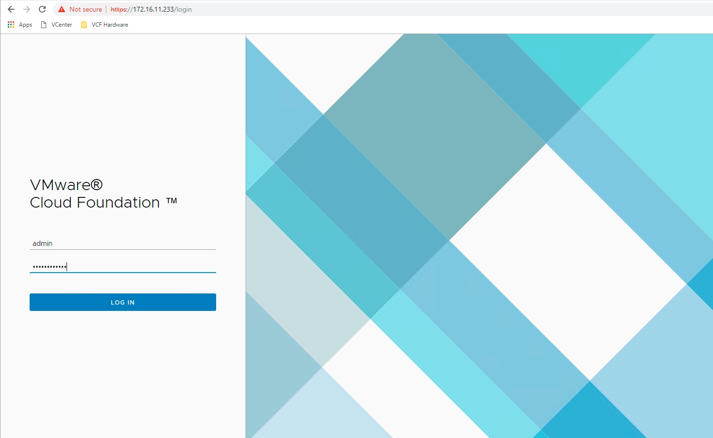
- Log in using the credentials that you specified during OVA deployment.
- Click Check All to review the checklist of pre-bring-up steps and confirm that all the steps that are completed, and then click Next.
- Review the EULA, and if you agree, click Agree to End User License Agreement, and then click Next.
- If you have not obtained and completed the Cloud Foundation Information Spreadsheet, click Download Deployment Parameter Sheet.
VMware Cloud Builder deployment parameter sheet
This worksheet is incorporated into the Cloud Builder VM and specific version of Cloud Foundation that is deployed. Save the worksheet to a safe location and edit the file modifying the information to match your deployment environment.
- Do not deploy Cloud Foundation using the deployment parameter sheet intended for a different version of Cloud Foundation.
- Any parameter field with a yellow background indicates that data format validation rules for that field have been specified.
- If when adding information to the parameter sheet your font turns red, you have not entered the right information.
- Do not copy and paste data between fields as different fields may have different requirements.
- Copying fields can change or delete the specified input data validation for that data.
VMware Cloud Builder parameters
Management Workload tab
- ESXi hosts
- vSAN
- vCenter
- NSX-T
- SDDC Manager Appliance
Users and Groups tab
In the Users and Groups tab, you can set the passwords for your initial VMware Cloud Foundation components.
Hosts and Networks tab
- Specify the VLAN IDs, subnets, gateways, and MTU for the networks that are used for the four required VMware Cloud Foundation networks.
- The MTU value should be the MTU size that can be tested during validation. For an actual MTU value of 9000 set this value to 9000.
- Specify the management IP addresses of the deployed hosts which are on the Cloud Foundation management VLAN.
- Specify the range of IP addresses for both the vSAN and vMotion networks.
- Host names that you enter in the Management Domain ESXi Hosts section are also auto-populated in the ESXi Host column of the ESXi Host Security Thumbprint section.
By default, use of DSA fingerprints as a more secure method to validate a host's authenticity is optional and disabled. Unique fingerprints are automatically generated on each host during installation. You can view the fingerprints using the DCUI under View Support Information. Due to the complexity of fingerprints, it is easier to access the hosts using SSH where they can be copied and pasted into the cloud builder deployment parameter sheet. Change the Validate ESXi Thumbprints option to Yes to enable fingerprint validation.
Deploy Parameters tab
- All the hostnames must be configured for forward and reverse look-ups.
- Test all the hostnames before attempting validation.
- Ensure that all the values provided are consistent with the values used to deploy the VMware Cloud Builder VM.
- The NTP server would have already been tested as the ESXi hosts have already been configured to this same NTP server(s).
- Change the hostnames that are listed and the domain that meets the customer required specifications.
- For a simplified network installation where a multi-tiered BGP environment is not available make sure that field K27 is set to No.
Run VMware Cloud Builder Deploy SDDC
- Turn on Cloud Builder VM.
- The VM must finish booting up and load the application stack.
- Using a web browser, go to the Cloud Builder web interface at https://<Cloud Builder IP Address>.
- Log in using the credentials that you specified during OVA deployment.
- Review the EULA, and if you agree, click Agree to End User License Agreement, and then click Next.
- Select VMware Cloud Foundation. Be sure not to select VMware Cloud Foundation on VxRAIL.
- Review the list of Prerequisites and ensure that they have all been completed
- Place a checkmark to indicate that the prerequisites have been met and select Next
- If you have not obtained and completed the Cloud Foundation Information Spreadsheet, click Download Deployment Parameter Sheet. If you have the parameter sheet click Next to move forward
- If you have not completed your parameter sheet do it now. If the parameter sheet is complete, click Next to continue.
- Click Select File to browse to your completed parameter sheet.
- Locate your completed parameter sheet and click Open.
- Click Next to begin the validation phase.
If validation discovers any issues in your configuration or parameter file, it shows an error and provides clear and detailed information on the issue. Read the message provided, correct the issue(s) and run the validation again. Validation can be run as many times as necessary to obtain a successful result.
- Once Validation has passed, and you have the green banner indicating that 'Configuration file validated successfully', click Next. A pop-up appears on the screen to Deploy SDDC Manager.
- Click DEPLOY SDDC to continue
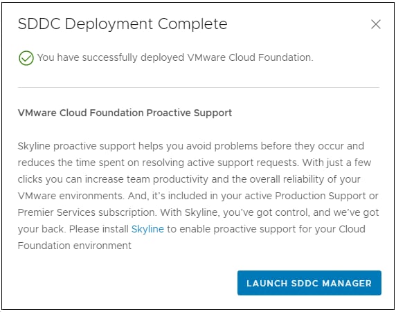
The deployment process begins. The deployment takes more than an hour. If the deployment completes successfully, a SDDC Deployment Complete pop-up message appears. If there were any issues, you can identify them in the VMware Cloud Foundationdeployment screen.
- Review any task failures and correct the issue. You can restart the deployment when you have resolved the issue(s).
- Click LAUNCH SDDC MANAGER
Figure 24. Pop-up window on successful SDDC deployment
VMware Cloud Builder Configuration Validation
- After you have completed the deployment parameter spreadsheet, click Upload, select the file, and then click Open.
A message is displayed to acknowledge successful upload of the parameter sheet.
- Click Validate and monitor progress on the Configuration File Validation page.
Figure 25. Configure Cloud Builder validation
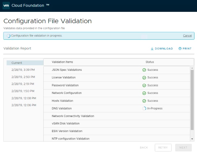
Note: Validation may take 15 minutes or more. However, if there are issues such as the DNS server being down or if you provided a wrong IP address, validation may take longer.
Note: On the Validation Report page, you can access the information about previous validation attempts. Each validation attempt is tracked with an entry that is designated by the date and time of execution.
- If the validation fails, expand the failed line item and review the detailed error messages. Some of the possible validation failures are shown in the following example.
Figure 26. Configuration validation error messages

- Resolve all the reported failures within the targeted servers, required services, network environment, or parameter spreadsheet, and then re-run validation in Cloud Builder by clicking Retry.
- Repeat Steps 1-4, until the validation is successful.
VMware SDDC bring-up
- In the Bringing Up the SDDC page, click Next to start the deployment of Cloud Foundation.
Note: You can monitor the deployment progress on the Bringing Up the SDDC page and this deployment process may require two hours or more, depending on your environment.
- If a bring-up failure occurs, expand the failed line item, review the detailed error messages. Depending on the nature of the error, resolve all the reported failures and click Retry.
Note: If an unrecoverable failure occurs during SDDC bring-up, it is necessary to resolve the root cause issue, wipe the Cloud Foundation target servers including all disk partitions, and then restart from the Deploy ESXi to cluster nodes section.
- The SDDC bring-up process is completed when the Cloud Builder reports that the SDDC has been successfully created.
When the SDDC bring-up process is complete, this indicates that the Cloud Foundation is successfully deployed.
- Access the recently deployed SDDC Manager by clicking the link on the page.
Figure 27. SDDC manager dashboard
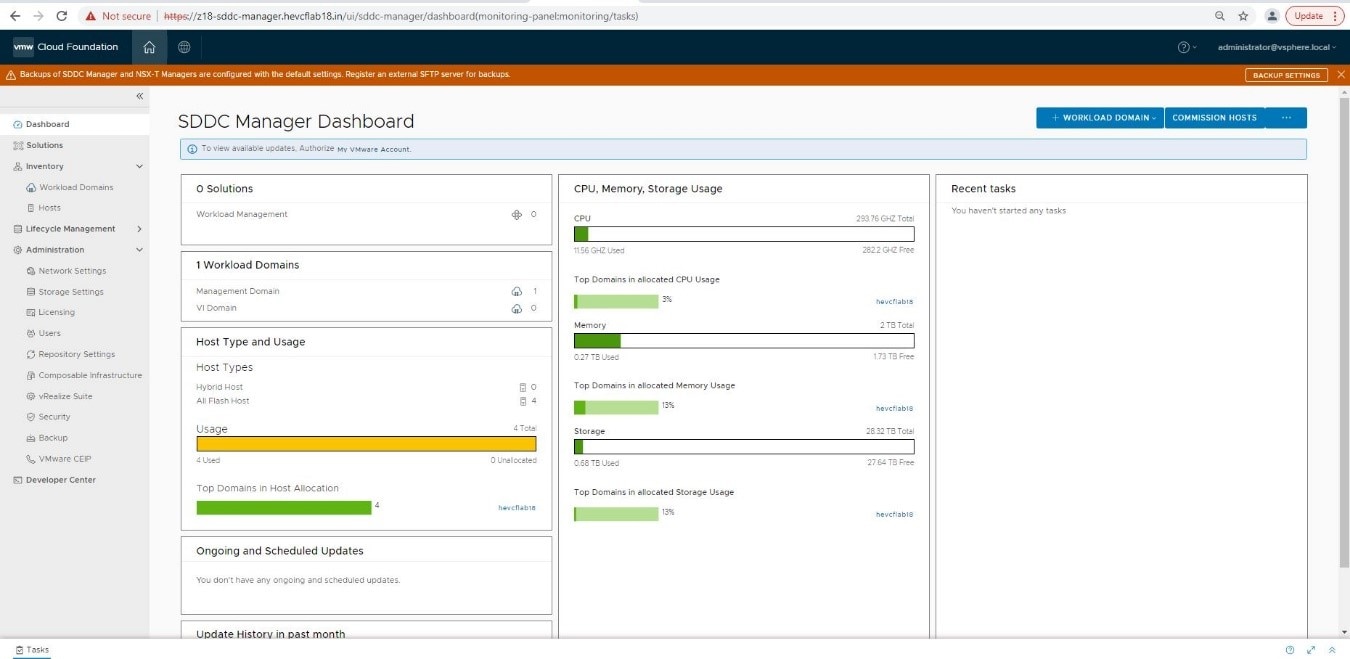
- Confirm deployment of vCenter, vSAN, NSX-T, and vRealize Log Insight.
Note: Hostnames and IP addresses are in the Cloud Foundation Deployment Parameters spreadsheet.
The Cloud Builder VM can now be discarded.
VMware VCF Post-installation Validation
VMware Cloud Foundation cluster verification
VMware SDDC Manager
Log in to VMware SDDC Manager using a web browser at: https://<ip address or DNS name>. The SSO user ID is administrator@vsphere.local and the password is the one you specified during installation.
vsphere.local . Do not use the DNS domain that was used for the Cloud Foundation deployment.
VMware Customer Experience Improvement Program
Join VMware Customer Experience Improvement Program (CEIP) when prompted. CEIP provides statistical data to SDDC Manager, allowing for improved performance and troubleshooting.
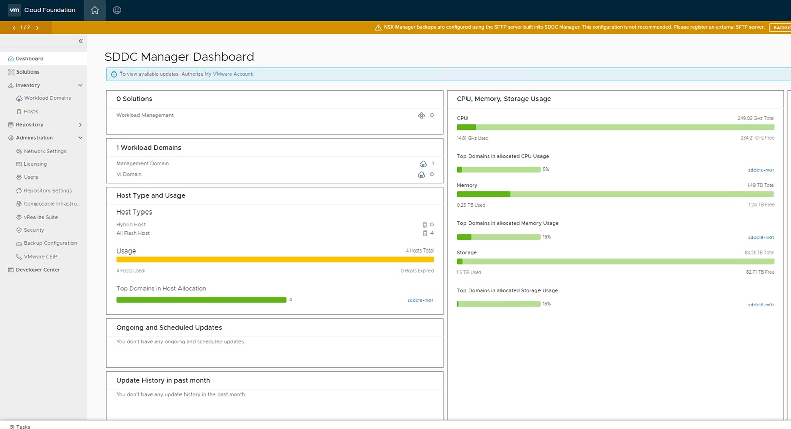
The following figure shows a sample SDDC Manager dashboard. In this example, the host usage is yellow because the management cluster has consumed all of the hosts currently available to Cloud Foundation.
VMware vCenter
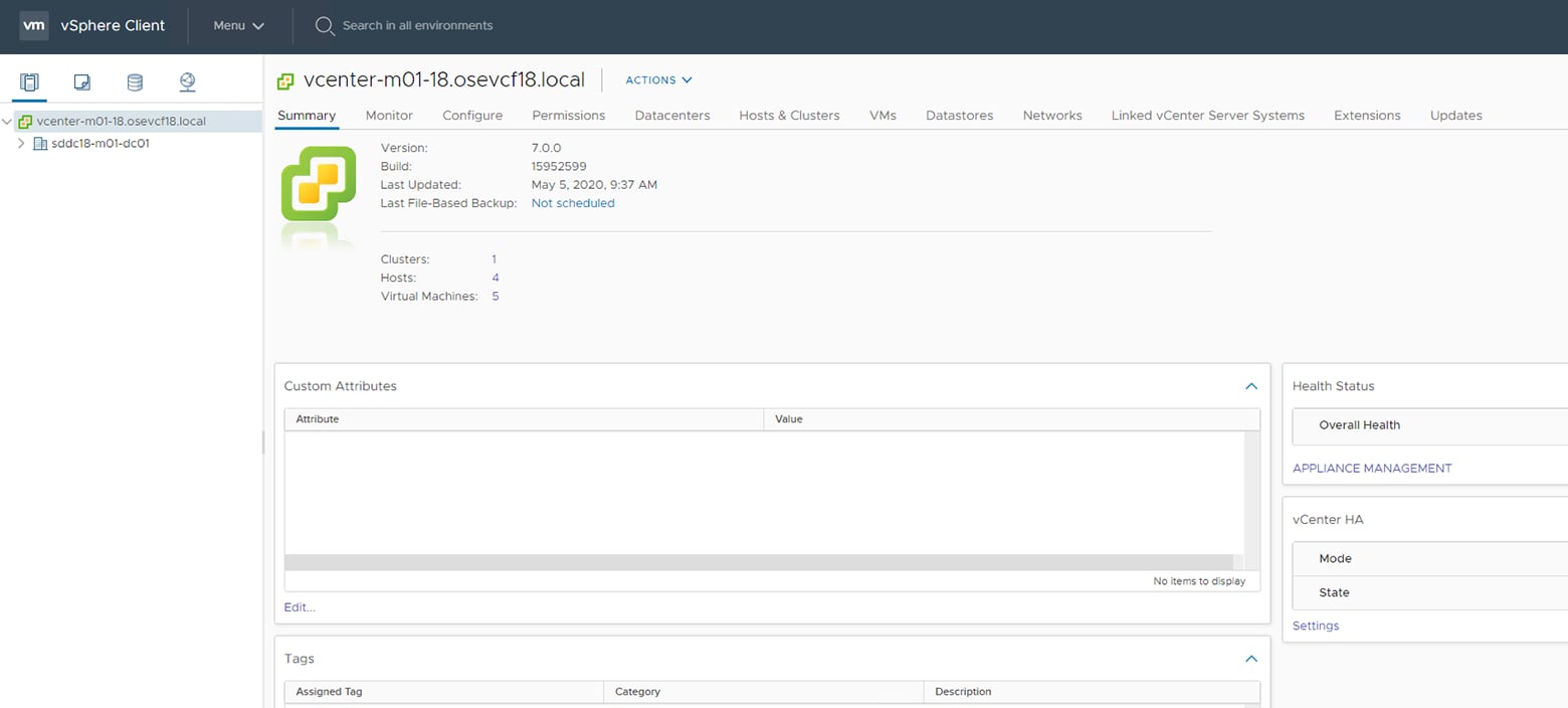
administrator@vsphere.local . Verify that the cluster appears healthy and that there are no warnings.
Validate that the VMs created during deployment are all up and running. Validate that your VSAN is running and available. Look at the disk groups that are created and ensure they are consistent with the disks available in the hosts. Look at the virtual networking components that are deployed to vCenter.
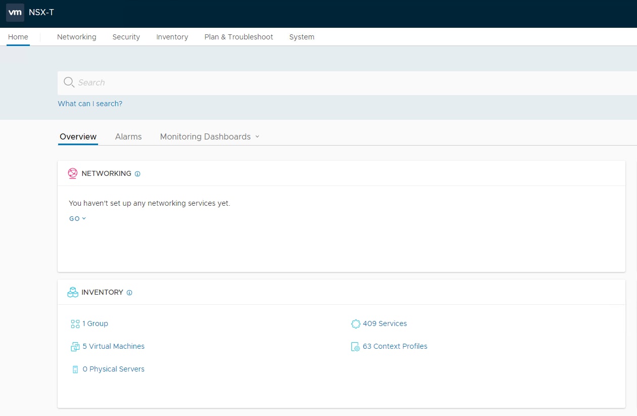
VMware NSX-T Manager
VMware Cloud Foundation installation complete
- Configure your VMware account credentials in SDDC manager
- If you chose simplified networking, configure your SDDC for VLAN backed Application Virtual Networks
- Install additional products such as:
- Life Cycle Manager
- vRealize Suite
- Other licensed bundles.
- Deploy a Workload Domain
Troubleshooting - VMware ESXi and VCF
Here is a list of common troubleshooting guidelines that can be used to solve common issues with VMware ESXi and VCF.
VMware ESXi host upgrade failures
Upgrading VMware ESXi 7.0 U2 from A05 to Patch 7.0 U2c with ESXCLI fails when you run the following command:
esxcli software profile update -p ESXi-7.0U2c-18426014-standard -d https://hostupdate.vmware.com/software/VUM/PRODUCTION/main/vmw-depot-index.xml
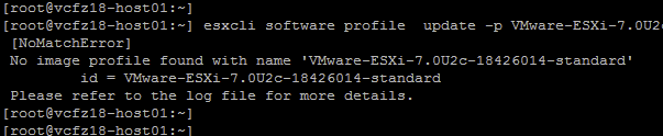
Sample log entries:
. . .
. . .
2021-10-27T14:01:11Z esxupdate: 2193582: root: ERROR: Traceback (most recent call last):
2021-10-27T14:01:11Z esxupdate: 2193582: root: ERROR: File "/usr/lib/vmware/esxcli-software", line 794, in <module>
2021-10-27T14:01:11Z esxupdate: 2193582: root: ERROR: main()
2021-10-27T14:01:11Z esxupdate: 2193582: root: ERROR: File "/usr/lib/vmware/esxcli-software", line 785, in main
2021-10-27T14:01:11Z esxupdate: 2193582: root: ERROR: ret = CMDTABLE[command](options)
2021-10-27T14:01:11Z esxupdate: 2193582: root: ERROR: File "/usr/lib/vmware/esxcli-software", line 252, in ProfileUpdateCmd
2021-10-27T14:01:11Z esxupdate: 2193582: root: ERROR: res = t.UpdateProfileFromDepot([], opts.profile, depotUrls=depoturls,
2021-10-27T14:01:11Z esxupdate: 2193582: root: ERROR: File "/lib64/python3.8/site-packages/vmware/esximage/Transaction.py", line 353, in UpdateProfileFromDepot
2021-10-27T14:01:11Z esxupdate: 2193582: root: ERROR: patcherVibs = _getPatcherForProfileCmd(profileName,
2021-10-27T14:01:11Z esxupdate: 2193582: root: ERROR: File "/lib64/python3.8/site-packages/vmware/esximage/Transaction.py", line 2550, in _getPatcherForProfileCmd
2021-10-27T14:01:11Z esxupdate: 2193582: root: ERROR: newProfile, _ = Transaction.GetProfileAndCompsFromSources(
2021-10-27T14:01:11Z esxupdate: 2193582: root: ERROR: File "/lib64/python3.8/site-packages/vmware/esximage/Transaction.py", line 1437, in GetProfileAndCompsFromSources
2021-10-27T14:01:11Z esxupdate: 2193582: root: ERROR: raise Errors.NoMatchError(profilename,
2021-10-27T14:01:11Z esxupdate: 2193582: root: ERROR: vmware.esximage.Errors.NoMatchError: ('VMware-ESXi-7.0U2c-18426014', "No image profile found with name 'VMware-ESXi-7.0U2c-18426014'")
Resolution
Run the following command:
esxcli software profile update -p ESXi-7.0U2c-18426014-standard -d https://hostupdate.vmware.com/software/VUM/PRODUCTION/main/vmw-depot-index.xmlAlternatively, upgrade ESXi with another method, such as vLCM.
VMware ESXi 7.0 U2c upgrade failure with error related to i40en
While updating the VMware ESXi 7.0 U2 host to ESXi 7.0 U2c, the upgrade might fail and the following entries might be logged in the esxupdate.log file:
2021-10-29T14:11:21Z esxupdate: 2102510: esxupdate: ERROR: File /tmp/esx-update-2102510/lib64/python3.8/site-packages/vmware/esximage/Transaction.py, line 928, in checkBaseImageUpgrade
2021-10-29T14:11:56Z esxupdate: 2102510: esxupdate: ERROR: esximage.Errors.InstallationError: This upgrade transaction would skip ESXi Base Image VIB(s) VMW_bootbank_i40en_1.11.1.31-1vmw.703.0.0.49537716, which could cause failures post upgrade. Please use an alternative upgrade method that would install the above VIB(s). For example, use an image profile instead of VIBs to perform the upgrade.
This is a known issue with upgrades. Refer to the following VMware knowledgebase article: https://kb.vmware.com/s/article/85982.
VMware ESXi CLI Commands
This section lists common commands that can be used to configure VMware ESXi hosts. You can run the commands via an SSH session.
NTP settings
| Setting | Command |
| Stop the ntpd service | esxcli system ntp set -e=no |
| Specify the NTP reference server by FQDN | esxcli system ntp set -s=ntp.osevcf.local |
| Specify the NTP servers by IP address | esxcli system ntp set -s=100.71.100.2 -s=100.71.100.3 |
| Start the ntpd service | esxcli system ntp set -e=yes |
DNS settings
| Setting | Command |
| Add a DNS search domain | esxcli network ip dns search add -d rainpool.com |
| Remove a DNS search domain | esxcli network ip dns search remove -d rainpool.com |
| Add a DNS server IP address | esxcli network ip dns server add -s 100.171.204.4 |
| Remove a DNS server IP address | esxcli network ip dns server remove -s 100.171.204.4 |
MTU settings
| Setting | Command |
| Configure the MTU on a vSwitch | esxcli network vswitch standard set -v=vSwitch0 -m 9000 |
| Configure the MTU on a VM kernel | esxcli network ip interface set -m 9190 -i vmk0 |
Configure VLAN ID on a portgroup
| Setting | Command |
| Set the portgroup "VM Network" to a VLAN ID of 1711 | esxcli network vswitch standard portgroup set --portgroup-name="VM Network" -v 1711 |
| Review the configuration of existing portgroups | esxcli network vswitch standard portgroup list |
Enable the CEIP (Customer Experience Improvement Program)
| Setting | Command |
| Enable the CEIP (Customer Experience Improvement Program) | esxcli system settings advanced set -o /UserVars/HostClientCEIPOptIn -i 2 |
Install depot files
Depot files are installed from the command line. Depot files must first be copied on to the server. There are many utilities that can be used to copy the depot file to the ESXi host. After the file has been copied, the following command will apply the updates contained in the depot file. The installation of the depot file update will not be complete until the host is rebooted.
esxcli software profile update -p VMware-ESXi-7.0U2c-18426014-standard -d /vmfs/volumes/datastore1/depot/VMware-ESXi-7.0U2c-18426014-depot.zipMaintenance mode
| Setting | Command |
| Enter maintenance mode | esxcli system maintenanceMode set --enable=true |
| Exit maintenance mode | esxcli system maintenanceMode set --enable=false |
Manual Switch Configuration (Optional)
Switch operating mode
MX7K-IOM-A2# show switch-operating-mode
MX7K-IOM-A2# Switch-Operating-Mode : Full Switch Mode
VLANs and subnets for manual switch configuration
interface vlan1711
description 1711-Mgmt
no shutdown
mtu 9216
interface vlan1712
description 1712-VMotion
no shutdown
mtu 9216
interface vlan1713
description 1713-VSAN
no shutdown
mtu 9216
interface vlan1714
description 1714-host-overlay
no shutdown
mtu 9216
interface vlan2711
description 2711-Uplink1
no shutdown
mtu 9216
interface vlan2712
description 2712-Uplink2
no shutdown
mtu 9216
interface vlan2713
description Edge-Overlay
no shutdown
mtu 9216
Uplink and VLTi ports
VLTi ports are specified during the configuration of the VLT domain by specifying the interconnect ports as discovery interfaces. The resulting VLTi port group cannot be managed manually. The VLT domain must be created on both VLT peer switches.
Configure the ports for VLTi
To configure the ethernet1/1/37 through 1/1/40 ports, ensure that the:
- Ports are preconfigured correctly.
- Ports are set to the correct frame size.
- Ports are not set in any switchport (VLAN) mode.
- Ports are not shut down.
interface ethernet1/1/40
no shutdown
no switchport
mtu 9216
flowcontrol receive off
Configure VLT domain
MX9116-A1(config)#
MX9116-A1(config)# vlt-domain 10
MX9116-A1(conf-vlt-100)# discovery-interface ethernet1/1/37,1/1/38,1/1/39,1/1/40
MX9116-A1(conf-vlt-10)# backup destination 100.71.242.220
MX9116-A1(conf-vlt-10)# exit
Verify VLT settings
MX9116-A1# show vlt 10
Domain ID : 10
Unit ID : 2
Role : secondary
Version : 2.3
Local System MAC address : 3c:2c:30:80:a8:80
Role priority : 32768
VLT MAC address : aa:bb:cc:11:11:11
IP address : fda5:74c8:b79e:1::2
Delay-Restore timer : 90 seconds
Peer-Routing : Disabled
Peer-Routing-Timeout timer : 0 seconds
VLTi Link Status
port-channel1000 : up
VLT Peer Unit ID System MAC Address Status IP Address Version
----------------------------------------------------------------------------------
1 3c:2c:30:80:aa:80 up fda5:74c8:b79e:1::1 2.3
MX9116-A1# show port-channel summary
Flags: D - Down I - member up but inactive P - member up and active
U - Up (port-channel) F - Fallback Activated
--------------------------------------------------------------------------------
Group Port-Channel Type Protocol Member Ports
--------------------------------------------------------------------------------
1 port-channel1 (D) Eth DYNAMIC 1/1/41(P) 1/1/42(P)
1000 port-channel1000 (U) Eth STATIC 1/1/37(P) 1/1/38(P) 1/1/39(P) 1/1/40(P)
Verify the VLTi (port-channel)
MX9116-A1#
MX9116-A1# show port-channel summary
Flags: D - Down I - member up but inactive P - member up and active
U - Up (port-channel) F - Fallback Activated
--------------------------------------------------------------------------------
Group Port-Channel Type Protocol Member Ports
--------------------------------------------------------------------------------
1000 port-channel1000 (U) Eth STATIC 1/1/37(P) 1/1/38(P) 1/1/39(P) 1/1/40(P)
MX9116-A1#
Configure the Link Aggregation Control Protocol
A VLT link aggregation is created by creating a VLT port channel on each of the MX9116N switches. First create the uplink VLT port channel on both switches and assign the appropriate VLANs.
Here are the port channels that are created on switch one:
MX9116-A1# show running-configuration interface port-channel 1
!
interface port-channel1
description "Uplink to DataCenter"
no shutdown
switchport mode trunk
switchport trunk allowed vlan 96, 1711-1714, 2711-2713
mtu 9216
vlt-port-channel 1
MX9116-A1# show port-channel summary
Flags: D - Down I - member up but inactive P - member up and active
U - Up (port-channel) F - Fallback Activated
--------------------------------------------------------------------------------
Group Port-Channel Type Protocol Member Ports
--------------------------------------------------------------------------------
1 port-channel1 (D) Eth DYNAMIC 1/1/41(P) 1/1/42(P)
1000 port-channel1000 (U) Eth STATIC 1/1/37(P) 1/1/38(P) 1/1/39(P) 1/1/40(P)
MX9116-A1#
MX9116-A1# show running-configuration interface port-channel 1
!
interface port-channel1
description "Uplink to DataCenter"
no shutdown
switchport mode trunk
switchport access vlan 1
switchport trunk allowed vlan 96, 1711-1714, 2711-2713
mtu 9216
vlt-port-channel 1
Configure the host facing ports
On switch one:
MX9116-A2(config)#
MX9116-A2(config)# interface range ethernet 1/1/1-1/1/16
MX9116-A2(conf-range-eth1/1/1-1/1/16)# switchport mode trunk
MX9116-A2(conf-range-eth1/1/1-1/1/16)# switchport trunk allowed vlan 96, 1711-1714, 2711-2713
MX9116-A2(conf-range-eth1/1/1-1/1/16)# mtu 9216
MX9116-A2(conf-range-eth1/1/1-1/1/16)# no shutdown
MX9116-A2(conf-range-eth1/1/1-1/1/16)# exit
MX9116-A2(config)#
On switch two:
MX9116-A2(config)#
MX9116-A2(config)# interface range ethernet 1/1/1-1/1/16
MX9116-A2(conf-range-eth1/1/1-1/1/16)# switchport mode trunk
MX9116-A2(conf-range-eth1/1/1-1/1/16)# switchport trunk allowed vlan 96, 1711-1714, 2711-2713
MX9116-A2(conf-range-eth1/1/1-1/1/16)# mtu 9216
MX9116-A2(conf-range-eth1/1/1-1/1/16)# no shutdown
MX9116-A2(conf-range-eth1/1/1-1/1/16)# exit
Save your switch configuration on each MX9116N switch using the following command:
MX9116-A2(config)# do write mem
Verify switch configuration
- All required VLANs and subnets
- VLT Domain
- VLTi
- VLT Link Aggregations
- Link Aggregations
- Host facing ports
Versions Used in This Guide
The following tables include the hardware, software, and firmware used to configure and validate the scenarios and topologies in this guide.
| Item | Version |
| PowerEdge MX7000 chassis | N/A |
| PowerEdge MX740c sled | A01 |
| PowerEdge M9002m modules (2 per chassis) | 1.30.10 |
| Networking MX9116n FSE (1 per chassis) | 10.5.2.5 |
| Networking MX7116n FEM (1 per chassis) | N/A |
| Item | Firmware version |
| PowerEdge MX740c sled | 1.30.10 baseline |
| Item | Version |
| ESXi - Dell Customized | 7.0U2, build 17867351 |
| ESXi depot (update) | 7.0U2, build 18426014 |
| Cloud Builder | 4.3.1.0 18624509 |
For more information about PowerEdge baselines, refer to Dell PowerEdge MX7000 Solution Baselines.
References
References
Dell Technologies documentation
The following Dell Technologies documentation provides additional and relevant information. Access to these documents may depend on your log in credentials. If you do not have access to a document, contact your Dell Technologies representative.
- Dell EMC Networking Guides
- Dell EMC PowerEdge MX IO Guide
- Dell EMC SmartFabric OS10 User Guide
- Dell EMC PowerStore Guides
- Dell Technologies Interactive Demo: OpenManage Enterprise Modular for MX solution management
- Dell EMC PowerEdge MX SmartFabric and Cisco ACI Integration Guide
- Manuals and documents for Dell EMC Networking MX5108n
- Manuals and documents for Dell EMC Networking MX9116n
- Manuals and documents for Dell EMC PowerEdge MX7000
- Manuals and documents for Dell EMC PowerSwitch S3048-ON
- Manuals and documents for Dell EMC PowerSwitch S5232-ON
- Manuals and documents for Dell EMC PowerSwitch S4148U-ON
- Fibre Channel Deployment with S4148U-ON in F_Port Mode
- FCoE-to-Fibre Channel Deployment with S4148U-ON in F_Port Mode
Dell PowerEdge MX7000 Solution Baselines
The Dell EMC OpenManage Enterprise-Modular Edition for PowerEdge MX7000 Chassis User's Guide provides information on new and previous versions of Dell MX7000 components. To find the version table, refer to the MX7000 Solution Baselines section in the chapter Updating firmware for PowerEdge MX solution.
The MX7000 Chassis baseline information can also be found in the Networking Support & Interoperability Matrix.
Dell Technologies Networking Infrastructure Solutions documentation
The following documentation provides additional networking solutions information.
Networking solutions: https://infohub.delltechnologies.com/t/networking-solutions-57/
Support and feedback
For technical support, visit https://www.dell.com/support.
We encourage readers to provide feedback on the quality and usefulness of this publication by sending an email to Dell_Networking_Solutions@Dell.com.