Dell PowerFlex File Replication using Datadobi StorageMAP
Executive summary
Executive summary
Introduction
Audience
Terminology
We Value your feedback
Product overview
PowerFlex family
PowerFlex software-defined infrastructure enables broad consolidation across the data center, encompassing almost any type of workload and architecture. The software-defined architecture offers automation and programmability of the complete infrastructure and provides scalability, performance, and resiliency to enable effortless adherence to stringent workload SLAs.
The PowerFlex family provides a foundation that combines compute and high-performance storage resources in a managed unified fabric. PowerFlex comes in flexible deployment options (rack, appliance, or custom nodes and in the public cloud) that enable independent (two-layer), HCI (single-layer), or mixed architectures. PowerFlex is ideal for high-performance applications and databases, building an agile private/hybrid cloud, or consolidating resources in heterogeneous environments.
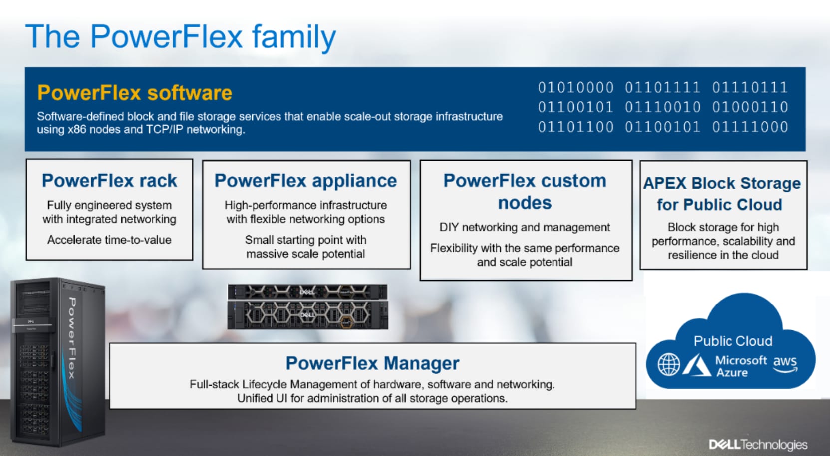
Figure 1. PowerFlex Family
PowerFlex software components
Software is the key differentiation in the PowerFlex offering. PowerFlex software components not only provide software-defined storage services, but also help simplify infrastructure management and orchestration. This software enables comprehensive IT Operational Management (ITOM) and Life Cycle Management (LCM) capabilities that span compute as well as storage infrastructure, from BIOS and Firmware to nodes, software, and networking.
PowerFlex
PowerFlex is the software foundation of PowerFlex software-defined infrastructure. It is a scale-out block and file storage service that is designed to deliver flexibility, elasticity, and simplicity with predictable high performance and resiliency at scale.
PowerFlex Manager
PowerFlex Manager is the software component in the PowerFlex family that enables ITOM automation and LCM capabilities for PowerFlex systems. Starting with PowerFlex 4.0, the unified PowerFlex Manager brings together three separate components used in previous releases – PowerFlex Manager, the core PowerFlex UI, and the PowerFlex gateway. The new PowerFlex UI runs in Kubernetes and embraces a modern development framework.
PowerFlex file services
PowerFlex File Controllers, also known as File Nodes, are physical nodes that enable PowerFlex software defined File Services. They host the NAS Servers, which in turn host the tenant namespaces and file systems, mapping PowerFlex volumes to the file systems presented by the NAS Servers. All major protocols are supported, such as NFS, SMB/CIFS, FTP, and NDMP. PowerFlex file service is supported from PowerFlex 4.0.
PowerFlex with NVMe over TCP (NVMe/TCP)
NVMe is a family of open specifications that defines an industry standard for both a logical interface and a communication protocol for accessing block storage across an internal PCIe fabric or through external fabrics such as TCP/IP and FC. NVMe is designed to take advantage of the internal parallelism and low latency inherent in flash-based media SSDs.
NVMe/TCP is an extension of the NVMe base specification that defines the binding of the NVMe protocol to message-based fabrics using TCP. By binding the NVMe protocol to TCP, NVMe/TCP enables the efficient end-to-end transfer of commands and data between NVMe hosts and NVMe controller devices by any standard Ethernet-based TCP/IP networks.
From PowerFlex release 4.x onwards, support for NVMe/TCP has been added for on-premises deployment with the introduction of a new Storage Data Target (SDT) component installed in the storage layer. The NVMe initiator in the operating system or hypervisor communicates with the SDT, which then communicates with the Storage Data Server (SDS). The NVMe initiator is part of the kernel of the application host operating system or hypervisor.
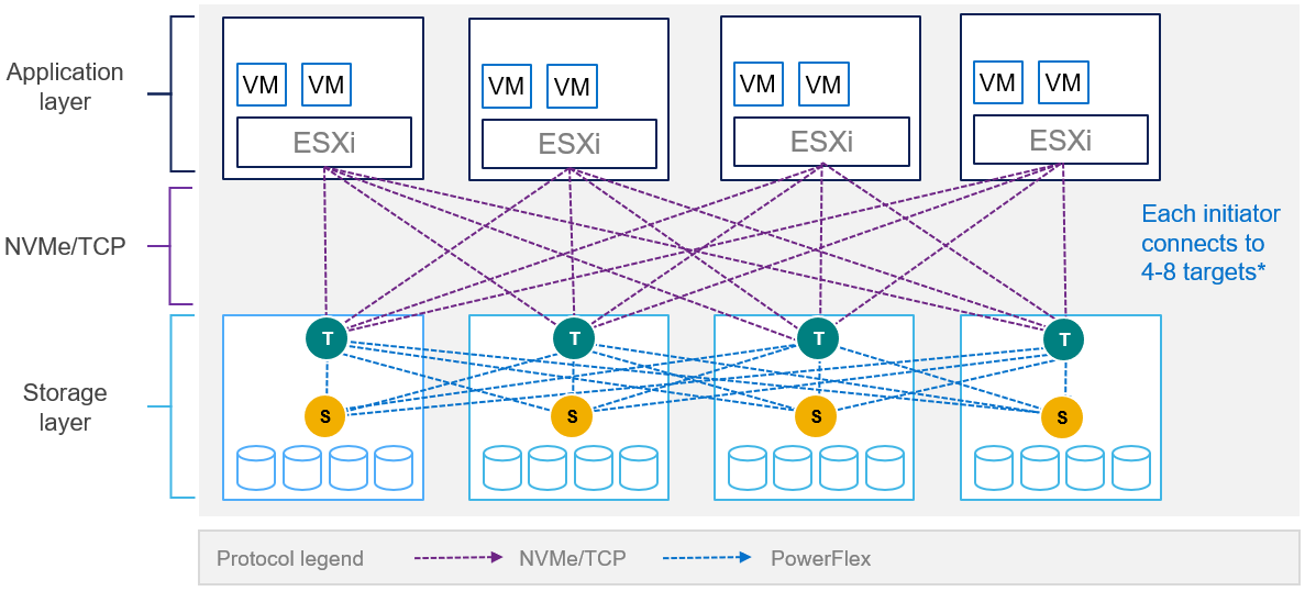
Figure 2. PowerFlex with NVMe/TCP
For more information, see PowerFlex with NVMe over TCP.
PowerFlex deployment architectures
PowerFlex software-defined storage offers flexibility of deployment architecture to help best meet the specific deployment and architectural requirements. PowerFlex can be deployed in a two-layer (Independent), single-layer (Hyperconverged/HCI), or a mixture of the two architectures (Mixed). OpenShift environments on PowerFlex use a two-layer (independent) architecture.
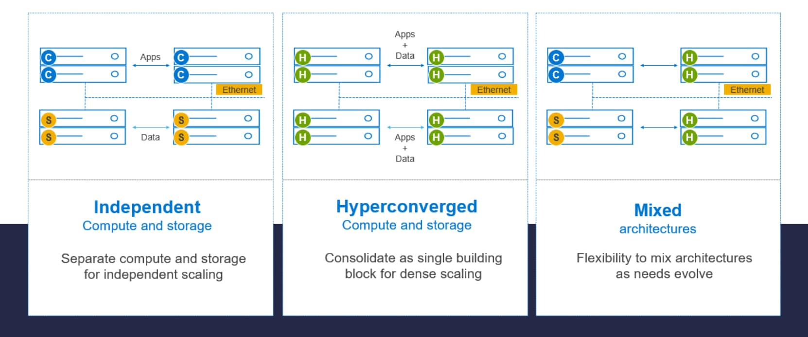
Figure 3. PowerFlex deployment architectures
Independent architecture
In an independent architecture, or two-layer architecture, some nodes provide storage capacity and host datasets while other, separate, and independent nodes, host applications and workloads. Compute and storage resources can be scaled independently by adding nodes to the cluster. This separation of compute and storage resources can also help minimize software licensing costs in certain situations. And this architecture can be ideal for hosting high-performance high-value databases and application workloads.
Hyperconverged architecture
In an HCI architecture, each node in the cluster contributes storage resources and hosts applications and workloads. This architecture allows you to scale your infrastructure uniformly and with a predefined building block that adds both storage and compute resources. This architecture is appropriate for data center and workload consolidation.
Mixed architecture
A mixed architecture is a combination of both the HCI and Independent architectures. As shown in Figure 3 there are some storages only nodes, compute only nodes, and HCI nodes as a part of the same PowerFlex cluster. This is a desirable architecture when working with an existing compute infrastructure and adding high-performance software-defined infrastructure. This can also be a starting point for a two-layer deployment design as external workloads are migrated to PowerFlex.
PowerFlex consumption options
PowerFlex rack
PowerFlex rack is a software-defined storage platform that delivers flexibility, elasticity, and simplicity with predictable performance and resiliency at scale by combining compute as well as high-performance storage resources in a managed unified network. This rack-scale engineered system, with integrated networking, enables customers to achieve the scalability and management requirements of a modern data center.
PowerFlex appliance
PowerFlex appliance is a PowerEdge server which has been configured to be a node in a software-defined storage deployment. This offering allows customers the flexibility and savings to bring their own compatible networking.
PowerFlex custom nodes
PowerFlex Custom Nodes are validated server building-blocks configured for use with PowerFlex. They are available with thousands of configuration options and are available for customers who prefer to build their own environments.
Dell APEX Block Storage for Public Cloud
PowerFlex software is also available in the public cloud as Dell APEX Block Storage for Public Cloud. It offers the same on-premises benefits of high-performance, linear scalability, and high resilience as in cloud. It also adds cloud-specific benefits, such as large volume sizes, extreme performance based on NVMe drives, and predictable scalability. The Dell APEX Block Storage self-healing architecture simplifies and increases the availability of infrastructure. It is designed to remain running even when it encounters failures. With fast rebuilds, Dell APEX Block Storage recovers rapidly from failures and keeps operating, without degrading performance or compromising availability. You can also extend this availability and configure it to protect your application availability across multiple availability zones.
PowerFlex CSI/CSM
An important component outside of PowerFlex that enables a flexible consumption model for Kubernetes is the PowerFlex CSI driver, developed as a part of the Dell Kubernetes strategy. After loading the CSI driver for PowerFlex into Kubernetes, it can be used to provision persistent volumes from the underlying PowerFlex storage resource. If the Kubernetes deployment is running low on PowerFlex storage resources, you can add PowerFlex storage nodes to increase the system capacity and performance.
The CSI driver connects the PowerFlex system and Kubernetes deployments. It is a storage broker which dynamically provisions volumes from PowerFlex through the PowerFlex API gateway to the Kubernetes cluster. Once the volume is available on PowerFlex, it is immediately mapped to the requesting pod. If a pod is destroyed or rescheduled, the CSI plug-in ensures that the volumes are remapped upon rescheduling of that pod.
- Customers running Kubernetes clusters on PowerFlex use the Dell Container Storage Modules (CSM), which extend the CSI driver capabilities. These modules:
- Provide enterprise storage capabilities to Kubernetes for cloud-native stateful applications.
- Reduce management complexity, so that developers can independently use enterprise storage with ease and automate daily operations.
- Extends storage functionality and capabilities beyond using the CSI driver alone.
These modules include snapshot, observability, authorization, application mobility, and resiliency.
PowerFlex supports multiple operating systems, different deployment options on-premises and public cloud deployment models (available in AWS and Azure). PowerFlex is validated with leading Kubernetes distributions as shown in Figure 4.
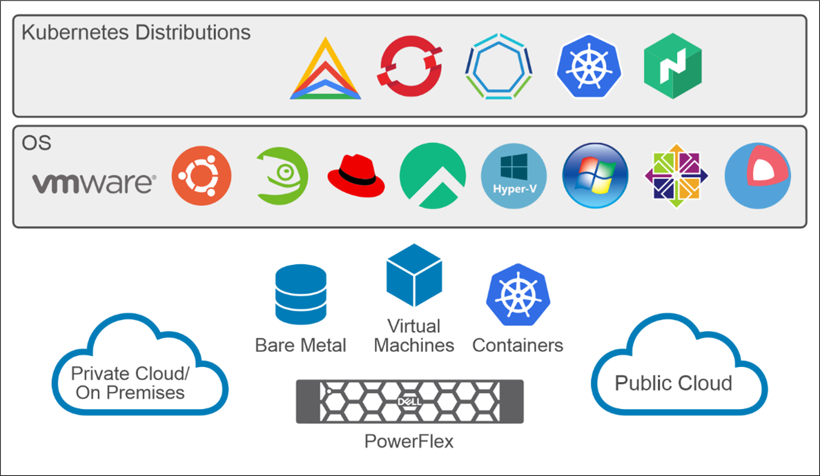
Figure 4. PowerFlex for different Kubernetes distributions
Datadobi StorageMAP
Solution overview
Overview
Logical architecture
The following image shows the logical architecture of the PowerFlex file clusters using two-layer deployment architecture.
In this example, on each site there are four nodes that are dedicated for storage. PowerFlex storage (SDS) components are installed on these four nodes, two nodes that are configured as PowerFlex file nodes and three more client nodes that are dedicated for running client applications consuming the file shares. This model decouples compute from storage, allowing either of them to scale independently, as needed.
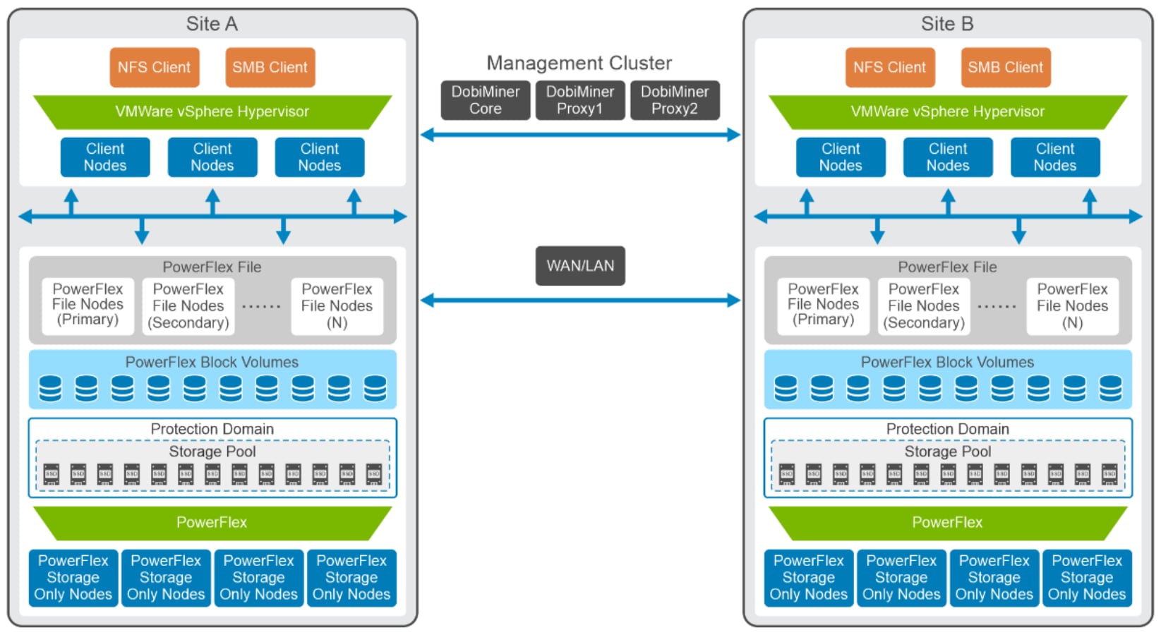
Figure 5. Logical design for PowerFlex file replication using StorageMAP
The client nodes are used to deploy Windows and Linux clients to mount the SMB and NFS file shares respectively. The DobiMiner core and DobiMiner proxies are installed and connected to both Site-A and Site-B File Servers.
On the storage side, PowerFlex Manager is used to deploy a PowerFlex storage node on four bare metal servers. Similarly, PowerFlex Manager is used to deploy PowerFlex file cluster on two PowerFlex file nodes.
For more information about installation and configuration of PowerFlex, see Dell PowerFlex Install and Upgrade Guide.
Network architecture
The following diagram shows the network architecture that is configured on both the sites.
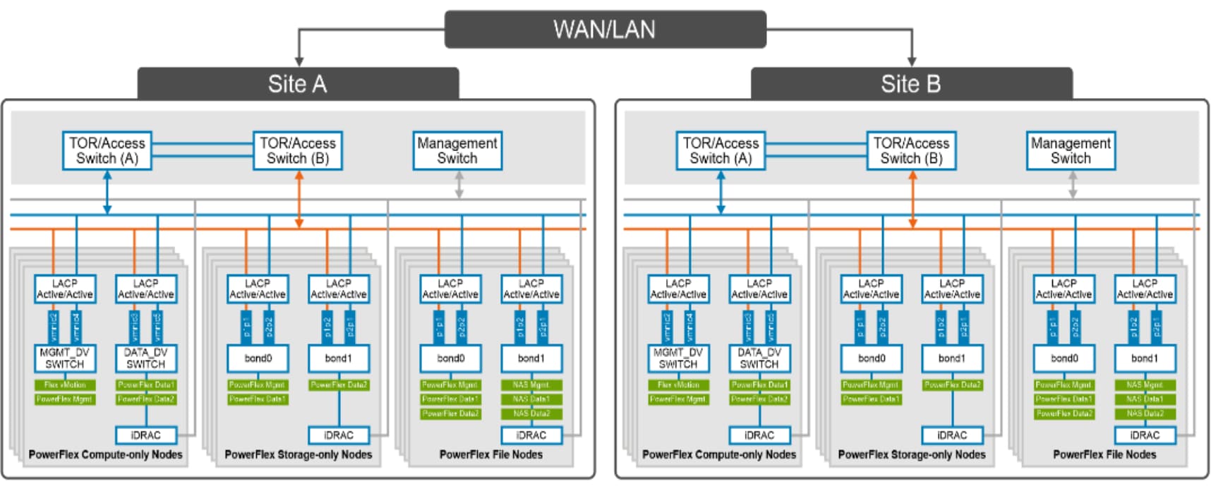
Figure 6. Network design for PowerFlex file replication using StorageMAP
At the physical layer, two Top of Rack (TOR) switches are used for redundancy and load-balancing purposes at each site. A peer link is configured on both the TOR switches.
The network ports of different network interfaces on each PowerFlex node are configured to carry PowerFlex management, PowerFlex data and PowerFlex file traffic. An LACP bond is configured at the host level with two network interfaces to form a single-bonded (logical) interface for increased bandwidth and redundancy.
The bond0 and bond1 are the LACP bonded interfaces and are configured with multiple VLAN tagged interfaces for all the PowerFlex networks. The traffic is logically separated by creating VLANs which separate different traffic on the bond interfaces as shown in the preceding figure. PowerFlex data1 and data2 are used for data traffic whereas NAS_data1 and NAS_data2 are dedicated for PowerFlex File data traffic.
The following table shows the different networks that are configured for this solution. For more information, see the PowerFlex node VLAN setup.
Table 2. Network details
|
Network type |
VLAN ID |
|
OS Management |
105 |
|
PowerFlex Management |
150 |
|
PowerFlex Data 1 |
151 |
|
PowerFlex Data 2 |
152 |
|
NAS Management |
250 |
|
NAS Data 1 |
251 |
|
NAS Data 2 |
252 |
Note: Based on the physical locations of Site-A and Site-B, it is recommended to enable (TOR-link) connectivity between the two sites for replication.
StorageMAP architecture
StorageMAP replication components can be deployed in any way - one proxy against multiple storage servers, many proxies to one storage server, and any other combination as long as the proxies are connected to both the source and target system.
Figure 7 shows the logical components that are involved in the functioning of file Replication using StorageMAP components.
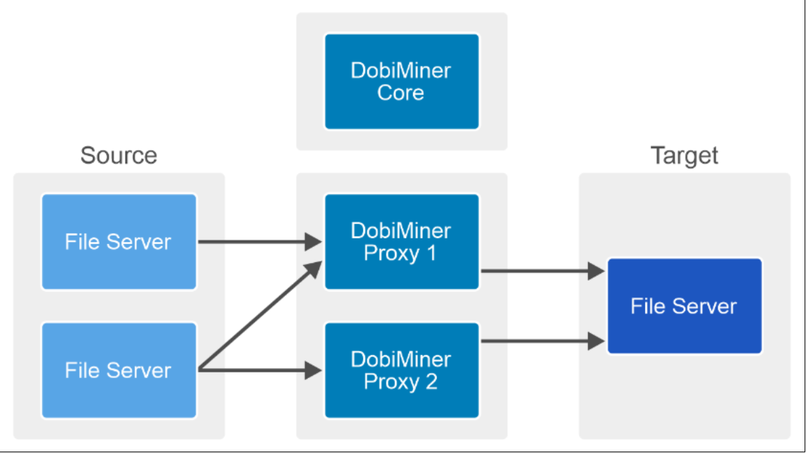
Figure 7. Logical components of StorageMAP
For details about the system requirements for DobiMiner Core and Proxy, see StorageMAP system requirements.
Note: To validate the replication use cases on SMB and NFS protocols, universal proxies are used.
Configuring PowerFlex file servers
Prerequisites
Prepare the PowerFlex file servers for replication
The following steps show how to create the PowerFlex file server at Site-A. Similar steps need to be performed at Site-B.
- Log in to PowerFlex Manager UI and click File > NAS Servers as shown in the following figure:
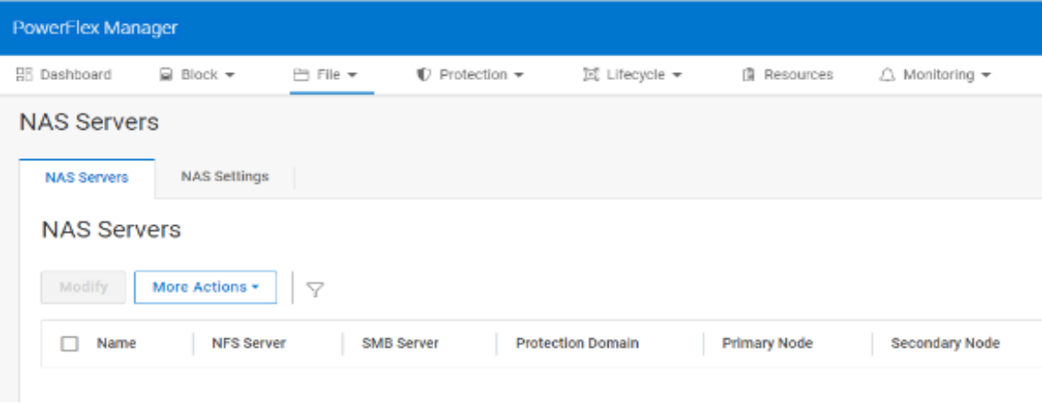
Figure 8. NAS Servers option in PowerFlex Manager UI
- Click Create NAS Server. Enter NAS Server Name, IP Address and select the NAS protection domain as shown in the following figure:
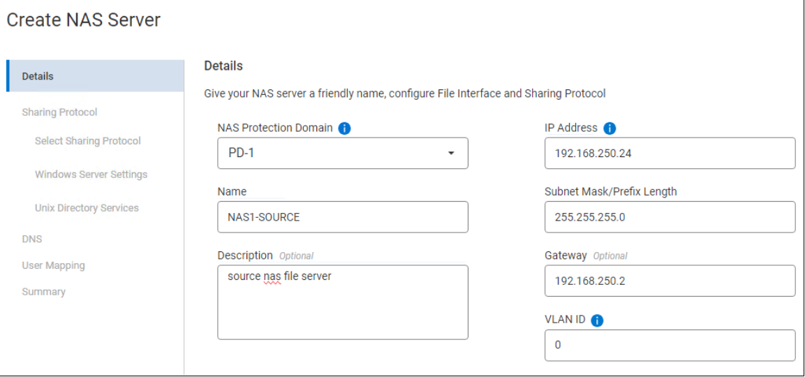
Figure 9. Create NAS Server
- Select the Sharing Protocol type: SMB, NFSv3, or NFSv4 as shown in the following figure:
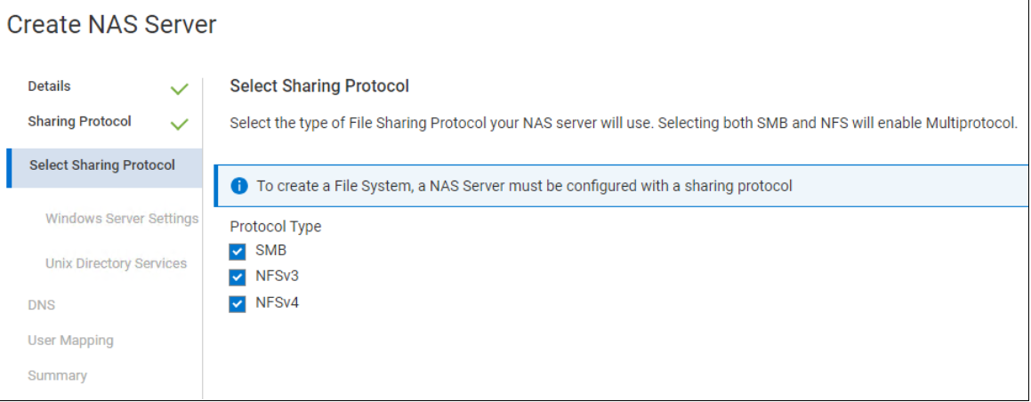
Figure 10. Select Sharing Protocol
- On Windows Server Settings, select Join to the Active Directory Domain and complete the Active Directory details. Click Next as shown in the following image,
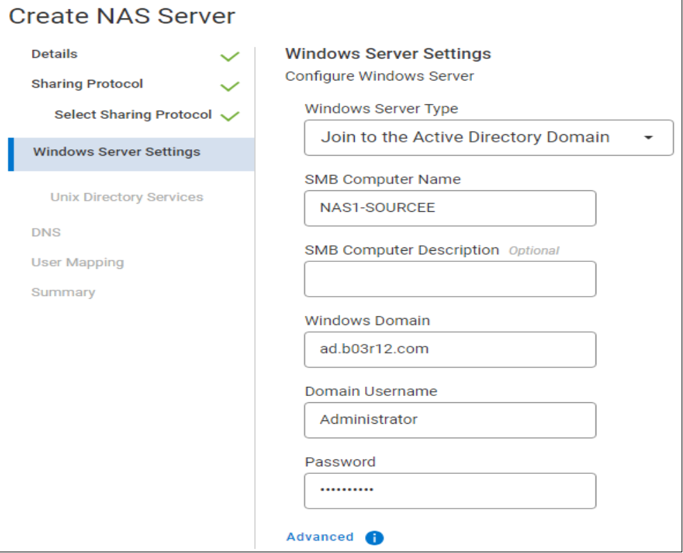
Figure 11. Windows Server Settings
- Enter DNS IP address and click Add. And then click Next.
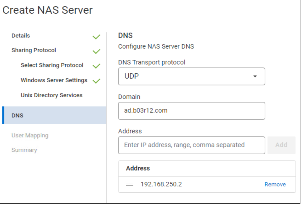
Figure 12. DNS details
- Click Create NAS Server as follows:
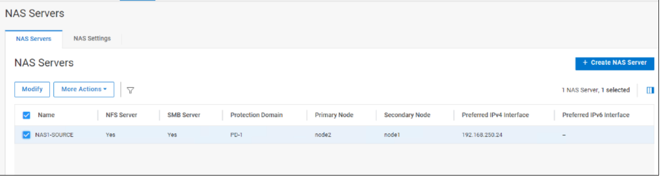
Figure 13. NAS File Server created
- Go to File > File Systems > Create File System as follows:
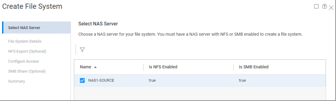
Figure 14. Create File System
- Select the Storage pool and enter the file system name and size. Click Next.
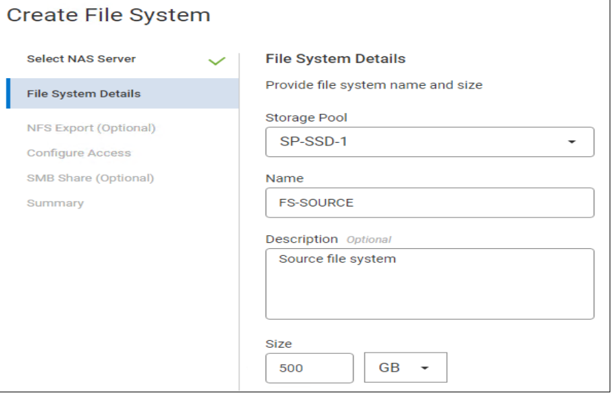
Figure 15. File System Details
- Enter the NFS Export details.
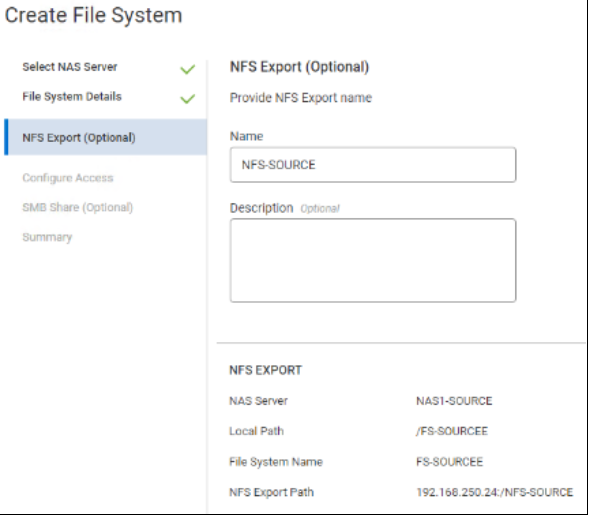
Figure 16. NFS Export Details
- Configure Access and select the default access to Read/Write, allow root as follows:
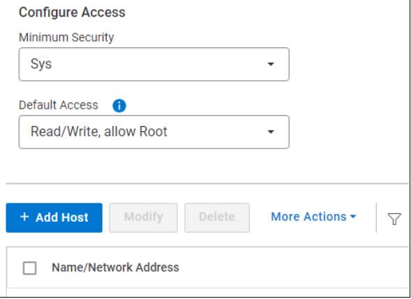
Figure 17. Configure Access
- Enter SMB Share details and click Create File System.
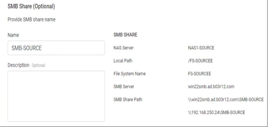
Figure 18. SMB Share details
Replication operations using StorageMAP
Prerequisites
Steps to add a file server
- To add a new file server, go to the Configuration module and click the File Servers option. Click the Add… button to open the Add New File Server dialog box as follows:
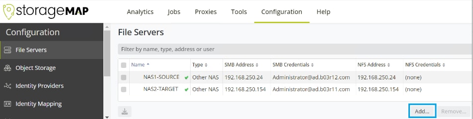
Figure 19. Add new file server
2. In the Add New File Server window, click Other NAS for PowerFlex File Servers.
3. Enter a name for the file server and specify the IP address (or DNS name) for data access by the NFS protocol.
4. For SMB shares, enter the SMB IP address and credentials. Make sure that the SMB account used is a member of the local administrators group and the local backup operators group. Refer the StorageMAP User Manual documentation for more details.
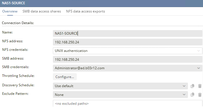
Figure 20. File server details
5. Select one or more proxies and click Test connection… to validate that the selected proxies can connect to the selected file servers using the credentials provided.
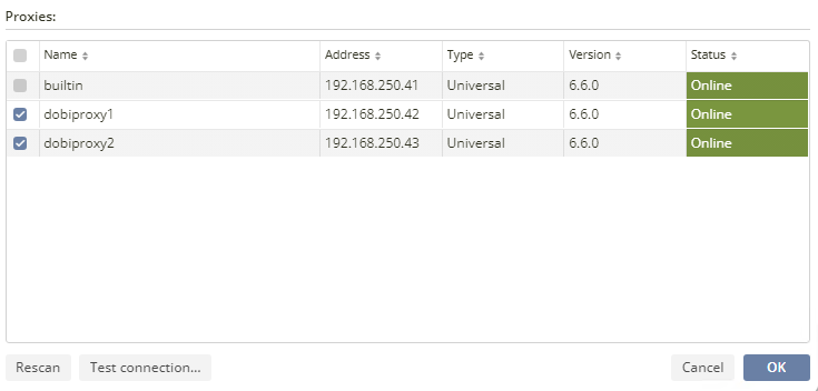
Figure 21. Proxies Test connection
6. The added file servers are now listed under the configuration tab as shown in the following figure:

Figure 22. Source and Target NAS File Servers
Start a replication
Steps to add a replication path
- To add a replication path, take the following steps: Go to the Jobs module and click the Replicate option as shown in the following figure:
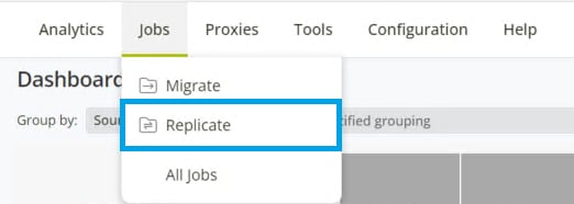
Figure 23. Replicate option
2. Click the New replication… button at the bottom right to open the Select source path window as shown in the following figure:
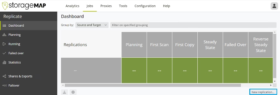
Figure 24. Create a new replication path
3. In Select source paths, select the source file server from the drop-down at the top as follows:

Figure 25. Select Source replication path
4. Select one or more target paths that need to be included in the replication as shown in the following figure. You can replicate at any level: The root or any level subdirectory.
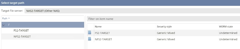
Figure 26. Select Target replication path
5. Click Next. The Select target path dialog box is displayed.
6. Select the target file server or bucket and location.
7. Create additional directories to serve as the root level for the replication data.
After the required prechecks are done, the Job options screen is displayed. If there are any precheck failures, StorageMAP displays the issues found and, depending on the issue, offer to fix it by changing the file server’s configuration as shown in the following figure:

Figure 27. Sample replication path
Replication options: General options
The following is a description of the key options in this screen.
- Iteration schedule - Allows you to define the frequency of the replication processes for the selected replication paths.
- Recovery point objective - This marks the time between the start of the last successfully completed replication iteration and the current time. Both iteration schedule and recovery point objective have options of default (configurable in system settings), pre-built intervals, and even a custom schedule which is represented by the “other” option (opens a window to allow a custom schedule to be created).
- Root directory handling - Allows you to determine how StorageMAP should copy the security (permission bits or ACL) of the root folder of the replication to the target. The available options are: Do not copy security, Copy security, and Convert inherited security to explicit.
- Excluded Path Pattern - Files or directories matching the pattern will be excluded from the replication.
The following figure shows the job options:
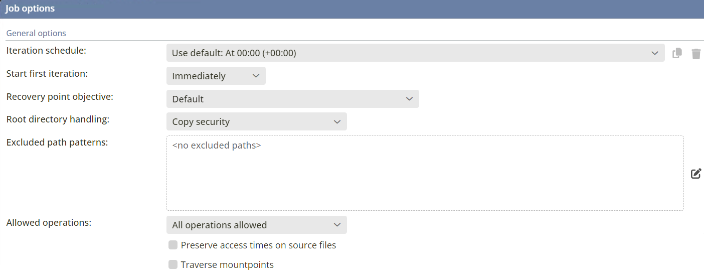
Figure 28. General Replication options
SMB replication options
The options shown in the following figure can be set for SMB replication for NAS-to-NAS scenarios:
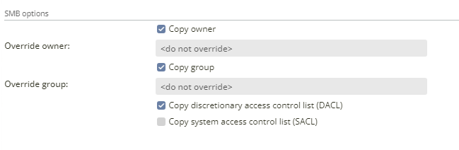
Figure 29. SMB replication options
- Copy owner: Setting this option copies the owner.
- Override owner: Enables you to override the owner. By default, do not override is set.
- Copy discretionary access control list (DACL): Setting this option copies the security descriptor. When not set, it is left blank on the data on the target file server.
- Copy system access control list (SACL): A SACL contains access control entries (ACEs) that specify the types of access attempts that generate audit reports. Each ACE identifies a trustee, a set of access rights, and a set of flags that indicate whether the system generates audit messages for failed access attempts, successful access attempts, or both.
NFS replication options
For the NFS replication options, select the appropriate NFS version as shown in the following figure:

Figure 30. NFS replication options
Manage replication options
When you run a replication, you can make changes in the Job options, regardless of the initial configuration and there is no need to stop replication or pause jobs. Job options can be changed at any time regardless of state.
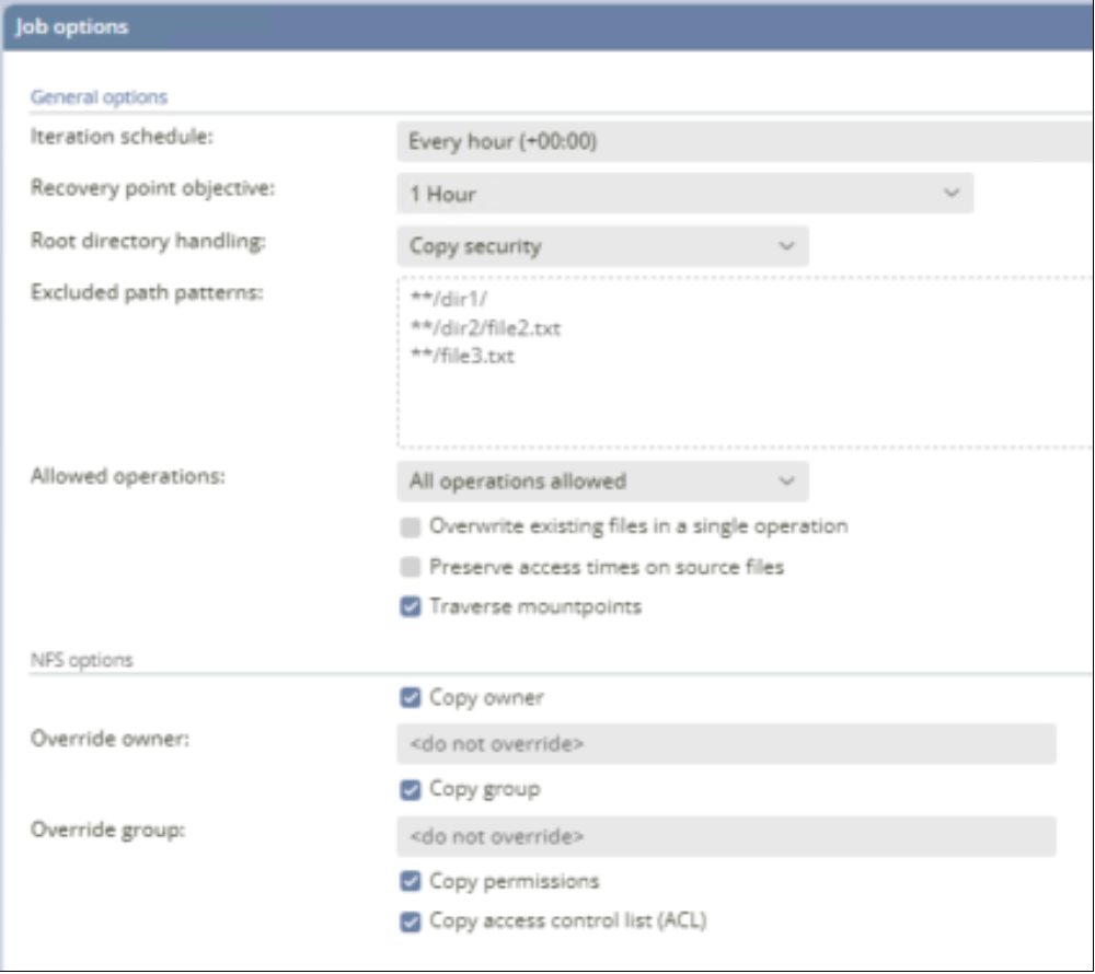
Figure 31. Running Job options
Manually start a replication iteration
In addition to using the automated scheduler, a replication session can be started at any time. This can be done by selecting the path from the list and clicking the Start button under the table. The following figure shows the new iteration window:
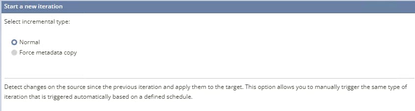
Figure 32. Manual replication iteration
If you select:
- Incremental: StorageMAP detects changes on the source since the previous iteration and applies it to the target.
- Verification: StorageMAP verifies the consistency between the source content and the target content and reports inconsistencies, if there are any.
Monitor replications
You can monitor the progress of a replication from different views and at various levels as shown in the following figure:
- High level: Through the Dashboard.
- Replication path level: Through the Iterations view.
- Process level: Through the Activity view.
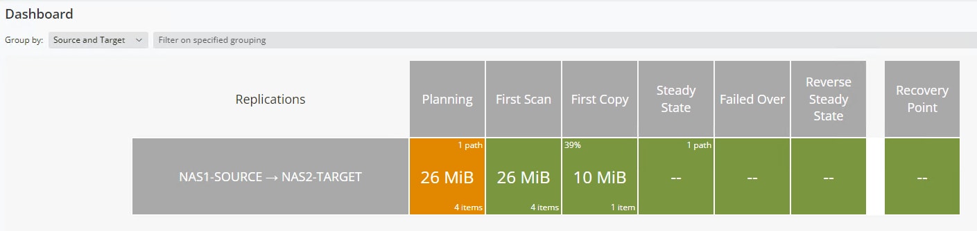
Figure 33. Dashboard for monitoring replications
View iteration details
You can open the iterations view via the Jobs module. Select the path of the currently running replication and click on the magnifying glass icon to see the details as shown in the following figure:
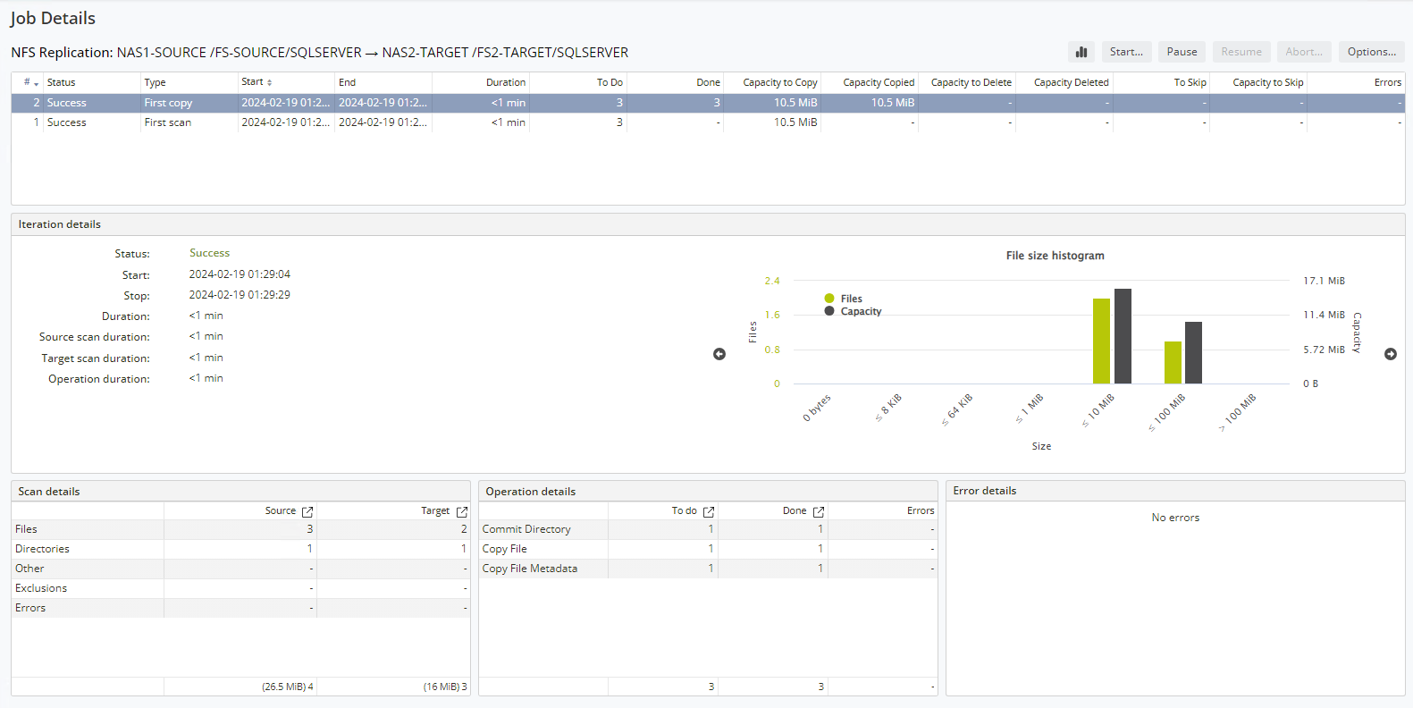
Figure 34. Detailed job description
Execute a planned failover
Start a failover
In this example, the source file server is brought down for a failover to the target.
- Click Replication module and then click the Failover tab.
- Select the replication path that you want for the planned Failover.
- Click Start new Failover as shown in the following figure:
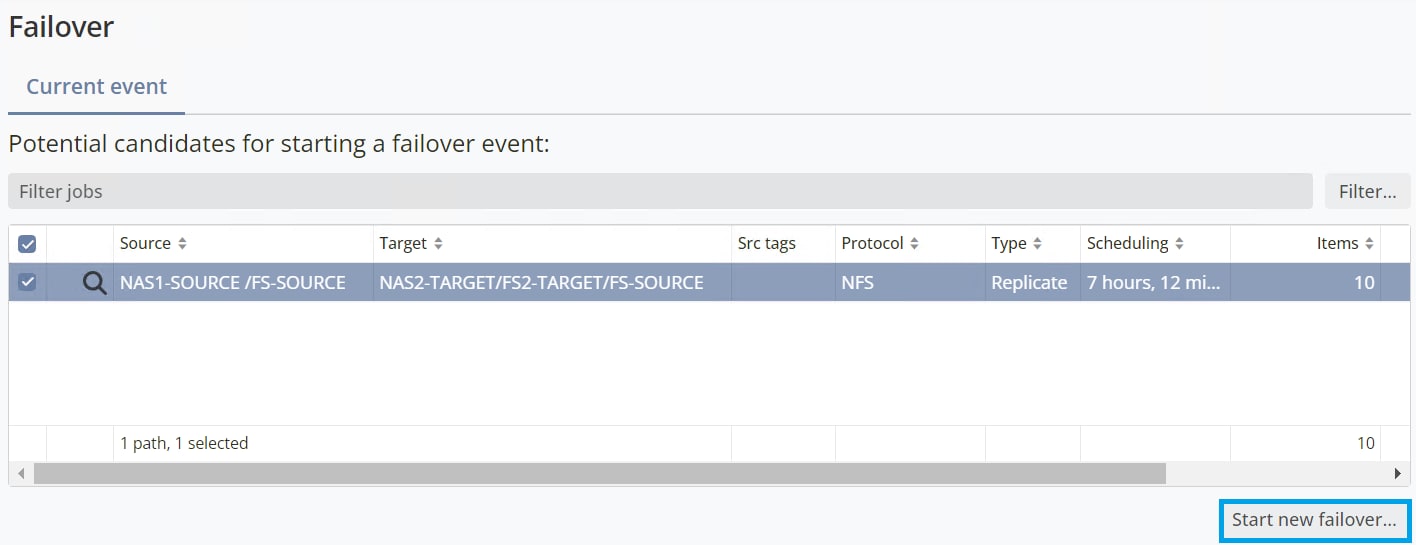
Figure 35. Starting a new failover
Update shares and exports
- Click the Shares & Exports Tab.
- Select the Failover path and change Mark Source access to Read only mode. And then click Start new failover as shown in the following figure:
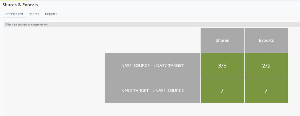
Figure 36. Monitor replications on Dashboard
Allow scheduling
- Go to the Failover tab to Shortlist and select the Failover path.
- Click the Schedule option at the bottom.
- Click Yes to proceed with the warning message. This warning message is to make Source File Server read only access.
- Click Yes to proceed with the warning message as follows:
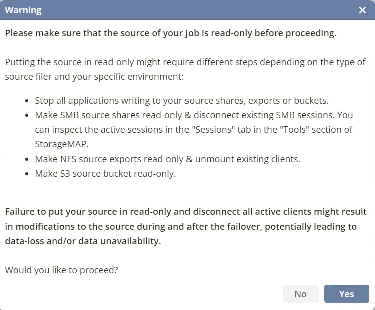
Figure 37. Warning message to make Source File Server read only access
Close a failover
1. Once the copy is completed and the summary shows as 100%, click Summary and then click Close Event… as follows:
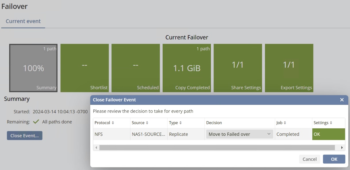
Figure 38. Closed failover event
Execute an unplanned failover
Update shares and exports
- Click the Share Settings as shown in the following figure:
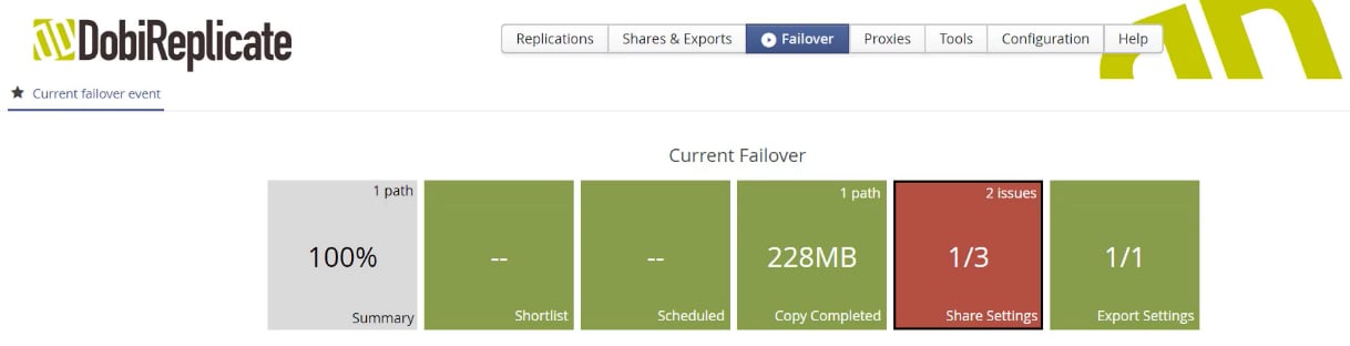
Figure 39. Unplanned failover share Settings
2. Select the path and click Fix.
3. Create the missing shares and click Next.
Start a reverse replication
Reverse replication
- Click Failed over module and select the path for reverse replication.
- Confirm the path for Reverse replication path.
- Review selected Jobs, Shares, and Exports and Click Next.
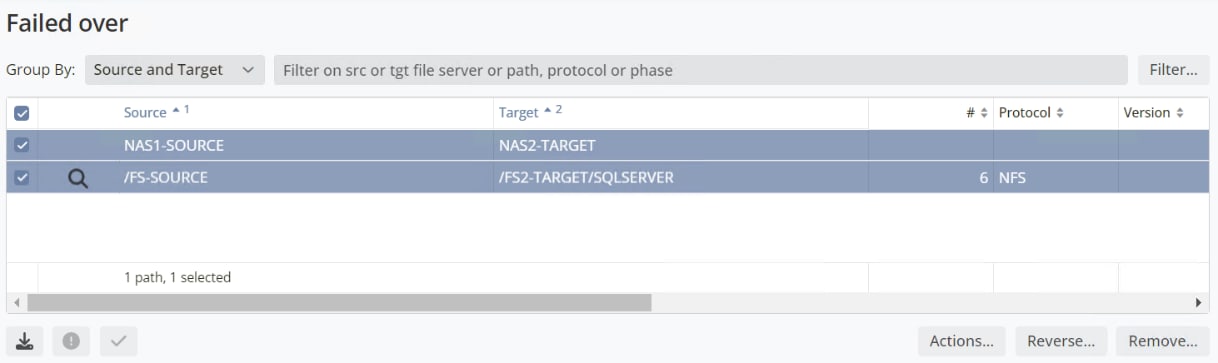
Figure 40. Reverse replication
Merge or full restore
- Click advanced options on the Job options.
- Choose Conflict Resolution Strategy as Full Restore or Merge.
- Full restore – In case of full restore, the original source file server is no longer in service and has been replaced with a new system that needs to be fully populated with date, shares and/or exports.
- Merge – In this case, merge assumes that the original source file server is back online and will merge the changes accumulated on the target file server post-failover back onto the original source file server.
3. Click Next and validate precheck results and then click Finish.
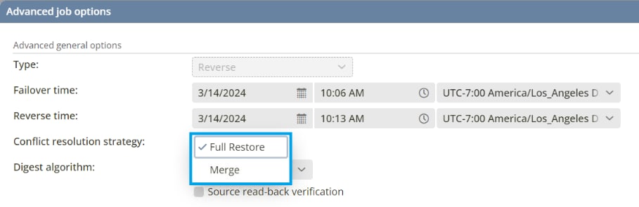
Figure 41. Advanced reverse job options full restore or merge
Start a failback
To move users back to the source file server, you need to repeat the Failover in reverse order called as Failback.
- Click Failed over module.
- Select the Reverse replication path that is currently running.
- Click the Start New Failover option and schedule the failover.
- Once the copy is completed then move the state to Failed over state as shown in the following figure:

Figure 42. Reverse replication failed over state
Revert the replication to steady state
Once the reverse replication is moved to failed over state, the user then will switch back to the source file server and the replication path needs to move back to steady state.
- Click the Failed over tab and select the replication path.
- Click To steady state action and click Next to move the path to steady state as follows:
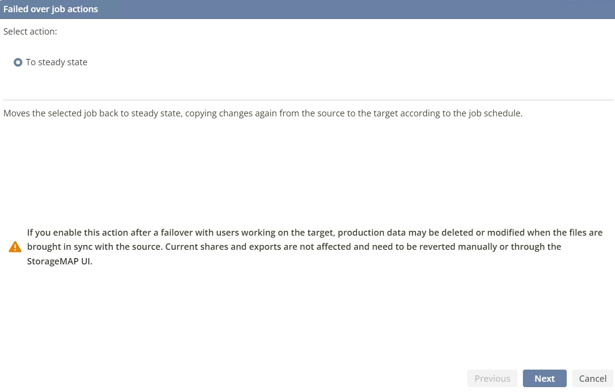
Figure 43. Revert the replication to steady state
3. This returns the setup back to the original replication steady state. Following the failback and the return to steady state, applications and end users can be directed to the original source system (or its replacement) for regular usage.

Figure 44. Back to the original replication state