
Deploying SingleStore Database on Dell PowerFlex 4.0

Deploying SingleStore Database on Dell PowerFlex 4.0 This white paper highlights the SingleStore deployment architecture, design considerations and best practices on a Dell PowerFlex infrastructure.

Introduction

Business challenges

Modern data management systems can benefit from aggregating resources of multiple systems into a cohesive pool in which applications can be consolidated and managed effectively. While the benefits of consolidating workloads is powerful, the action of data consolidation can face difficulties such as system management, performance management, and database configuration for optimal performance. Particularly for analytics applications, the database management system must have the ability to ingest large volumes of data, merge and aggregate data, streamline data management, and enable fast analytics operations.

SingleStore is a distributed relational database that natively supports structured, semi structured, JSON, geospatial, key-value, and time series data. The capability to support multiple data types presents the opportunity for data consolidation. SingleStore also features a data ingestion technology called SingleStore Pipelines. This technology streams large amounts of data at high throughput into the database with exactly once semantics. Using exactly once semantics, each message in a complex distributed system is delivered once and not duplicated or lost in the transfer.

Dell PowerFlex delivers scale-out storage that adds resiliency to the SingleStoreDB and automates storage self-balancing. PowerFlex flexibility contains self-healing, snapshots, asynchronous replication, performance management, security, and enterprise support.


Document purpose

This white paper describes the deployment architecture of the SingleStore on the PowerFlex single-layer HCI architecture. This paper also outlines the PowerFlex design considerations to achieve optimal SingleStore performance in a VMware vSphere environment.

Note: This paper may contain language from third-party content that is not under Dell's control and is not consistent with Dell's current guidelines for Dell's own content. When such third-party content is updated by the relevant third parties, this document will be revised accordingly.

Audience

This white paper is intended for SingleStore administrators, sales engineers, field consultants, IT architects, and IT managers.

Readers are expected to have an understanding and working knowledge of SingleStore, PowerFlex, VMware vSphere, PowerFlex appliance, and PowerFlex Manager.

Terminology

The following table provides abbreviations for some of the key terms that are used frequently in this document.

Table 1.  Terminology

Term

Definition

DDL

Data Definition Language

HTAP

Hybrid Transactional and Analytical Processing

HCI

Hyperconverged Infrastructure

ITOM 

IT Operational Management

LCM

Life Cycle Management

NIC

Network Interface Card

OLAP 

Online Analytical Processing

OLTP

Online Transaction Processing

OS

Operating System

PVSCSI

Paravirtual SCSI

SDS

Storage Data Server

SDC

Storage Data Client

TCO

Total Cost of Ownership

VM

Virtual Machine

VLAN

Virtual LAN

PowerFlex overview

PowerFlex family

PowerFlex software-defined infrastructure enables broad consolidation across the data center, encompassing almost any type of workload and architecture. The software-defined architecture offers automation and programmability of the complete infrastructure and provides scalability, performance, and resiliency to enable effortless adherence to stringent workload SLAs. 

The PowerFlex family provides a foundation that combines compute and high-performance storage resources in a managed unified fabric. PowerFlex comes in flexible deployment options (rack, appliance, or custom nodes and in the public cloud) that enable independent (two-layer), HCI (single-layer), or mixed architectures. PowerFlex is ideal for high-performance applications and databases, building an agile private/hybrid cloud, or consolidating resources in heterogeneous environments.
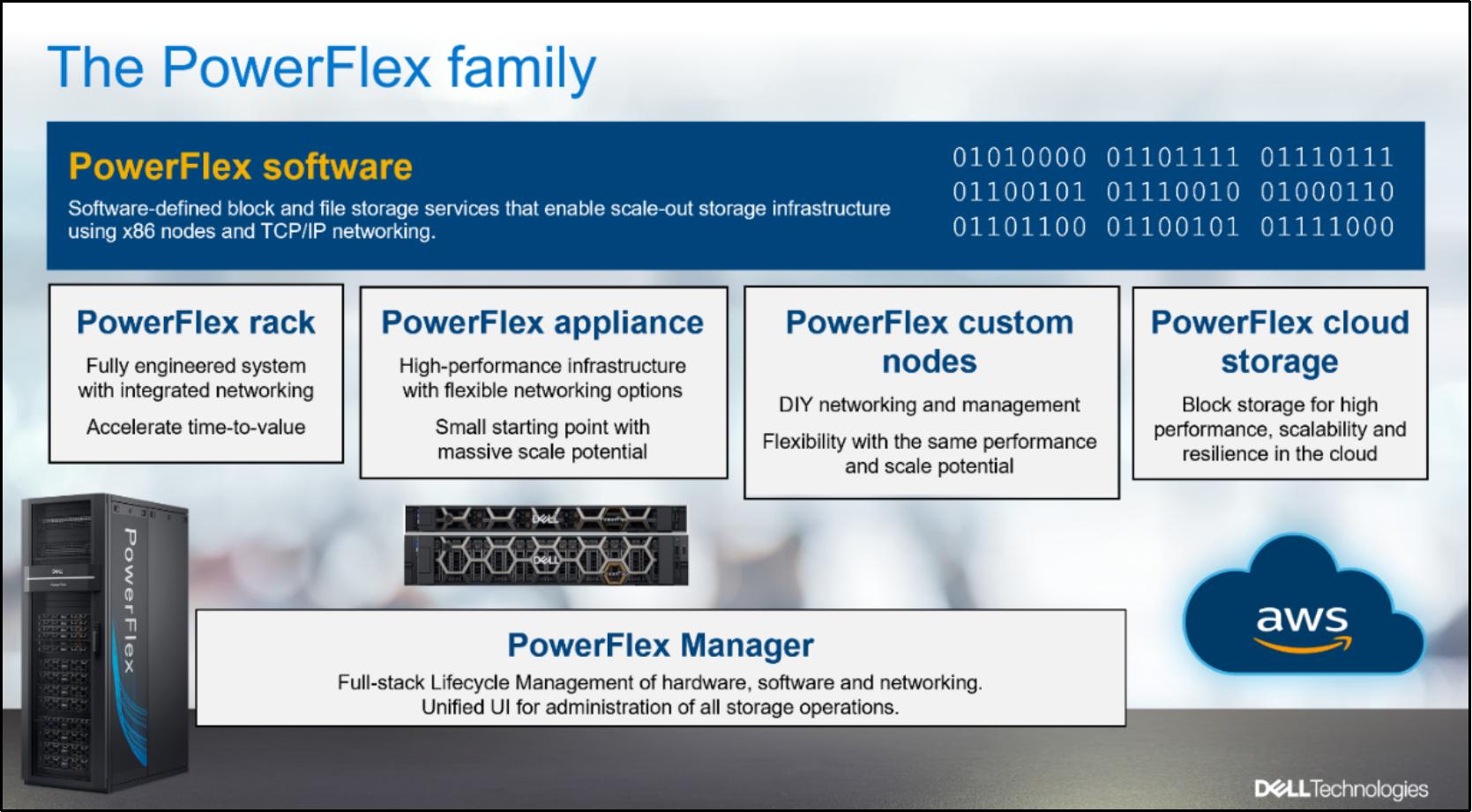
Figure 1.  PowerFlex family

PowerFlex software components  

Software is the key differentiation in the PowerFlex offering. PowerFlex software components provide software-defined storage services and also help simplify infrastructure management and orchestration. This enables comprehensive IT Operational Management (ITOM) and Life Cycle Management (LCM) capabilities that span compute and storage infrastructure, from BIOS and Firmware to nodes, software, and networking. 

PowerFlex 

PowerFlex is the software foundation of PowerFlex software-defined infrastructure. It is a scale-out block and file storage service that is designed to deliver flexibility, elasticity, and simplicity with predictable high performance and resiliency at scale.  

PowerFlex Manager 

PowerFlex Manager is the software component in PowerFlex family that enables ITOM automation and LCM capabilities for PowerFlex systems. Starting with PowerFlex 4.0, the unified PowerFlex Manager brings together three separate components used in the previous releases: PowerFlex Manager, the core PowerFlex UI, and the PowerFlex gateway. The new PowerFlex UI runs in Kubernetes and embraces a modern development framework. 

PowerFlex File Services  

PowerFlex File Controllers, also known as File Nodes, are physical nodes that enable PowerFlex software-defined File Services. They host the NAS Servers, which in turn host the tenant namespaces and file systems, mapping PowerFlex volumes to the file systems presented by the NAS Servers. All major protocols are supported, such as NFS, SMB/CIFS, FTP, and NDMP. 

PowerFlex deployment architectures

PowerFlex software-defined infrastructure excels in deployment flexibility. PowerFlex can be deployed in a two-layer (independent compute and storage layers), single-layer (Hyperconverged Infrastructure, or HCI), or a mixture of the two architectures (Mixed). 
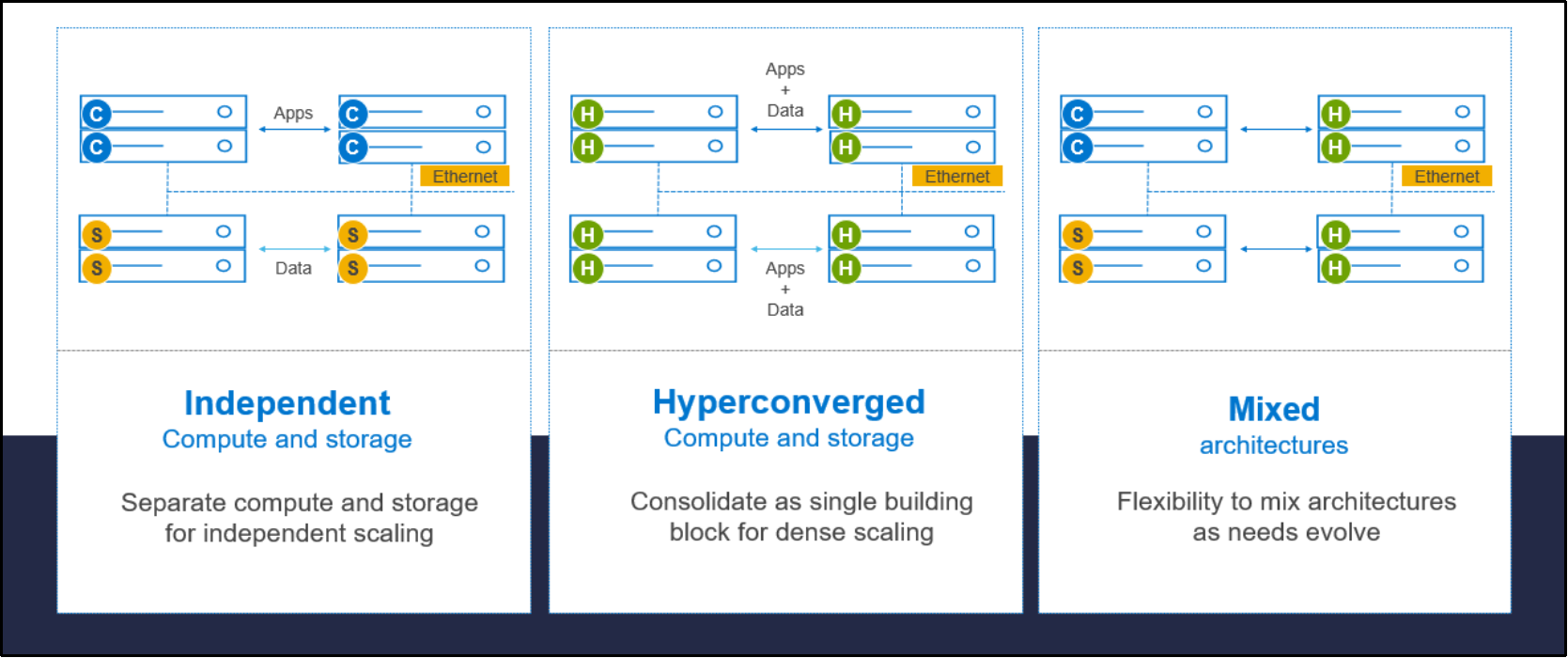
Figure 2.  PowerFlex deployment architectures

Independent architecture 

In an independent architecture, or two-layer architecture, some nodes provide storage capacity for applications data while other separate and independent nodes provide compute resources for applications and workloads. Compute and storage resources can be scaled independently by adding nodes to the cluster while it remains active. This separation of compute and storage resources can help minimize software licensing costs in certain situations. This architecture is ideal for high-performance databases and application workloads. 

Hyperconverged architecture 

In an HCI architecture, each node in the cluster contributes storage and compute resources simultaneously to the applications and workloads. This architecture allows you to scale your infrastructure uniformly with building blocks that add both storage and compute resources. This architecture is appropriate for data center and workload consolidation. 

Mixed architecture 

In a mixed architecture, we have a combination of both the HCI and Independent architectures. As shown in Figure 2‎ there are some storage only nodes, compute only nodes, and HCI nodes that are part of the same PowerFlex cluster. This is a desirable architecture when working with an existing compute infrastructure and adding high-performance software-defined infrastructure. This is also a starting point for a two-layer deployment design when external workloads are migrated to PowerFlex.

PowerFlex Consumption Options

PowerFlex rack 

PowerFlex rack is a software-defined infrastructure platform that delivers flexibility, elasticity, and simplicity with predictable performance and resiliency at scale by combining compute as well as high-performance storage resources in a managed unified network. This rack-based engineered system has integrated networking and enables customers to achieve the scalability and management requirements of a modern data center.  

PowerFlex appliance 

PowerFlex appliance is a PowerEdge server which has been configured as a node in a software-defined infrastructure deployment that runs PowerFlex software components. This offering allows customers the flexibility and savings to bring their own compatible networking. 

PowerFlex Custom Nodes 

PowerFlex Custom Nodes are validated server building-blocks configured for use with PowerFlex. Custom nodes are available with thousands of configuration options and customers can build their own environments.

PowerFlex on AWS 

PowerFlex software can be deployed in the public cloud and is available in the Amazon Marketplace as PowerFlex cloud storage. PowerFlex on AWS offers the same on-prem benefits of high-performance, linear scalability, and high resilience as in the cloud. PowerFlex also adds cloud-specific benefits, such as large volume sizes, extreme performance based on NVMe drives, and predictable scalability. With PowerFlex on AWS, you can also get higher multi-Availability-Zone (multi-AZ) resiliency when PowerFlex Fault sets are distributed across multiple AWS Availability Zones.

SingleStore overview

SingleStore overview

SingleStore is a distributed, relational database that handles both transactions and real-time analytics at scale. It is accessible through standard SQL drivers and supports ANSI SQL syntax including joins, filters, and analytical capabilities. For example, aggregates, group by, and windowing functions.

The SingleStoreDB: 

  • Scales horizontally on cloud instances or industry-standard hardware, providing high throughput across a wide range of platforms. 
  • Maintains a broad compatibility with common technologies in the modern data processing ecosystem (for example, orchestration platforms, developer IDEs, and BI tools), so you can easily integrate it with your existing environment. 
  • Features an in-memory rowstore and an on-disk columnstore to handle both highly concurrent operational and analytical workloads. 
  • Features the SingleStore Pipelines data ingestion technology that streams large amounts of data at high throughput into the database with exactly once semantics. 
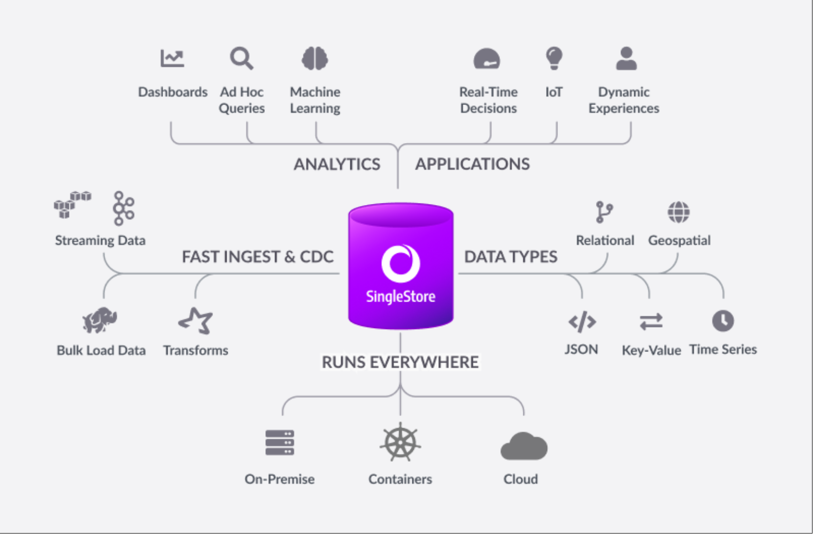
Figure 3.  SingleStore database overview


SingleStore cluster components

A SingleStore cluster has the following components:

Leaf

A leaf is a node that stores a subset of a cluster’s data. It functions as a storage and compute node. To optimize performance, SingleStore automatically distributes data across leaf nodes into partitions. Each leaf contains several partitions. A cluster contains many leaves, and each leaf is in one of the Leaf States.

Aggregator

An aggregator is a node that routes queries to the leaves, aggregates intermediate results, and sends the results back to the client. There are two types of aggregators: master and child. 

A master aggregator is a specialized aggregator responsible for cluster monitoring and failover. It orchestrates the basic cluster operations and all data definition language (DDL) operations. For more information, see Aggregator set as master.

A cluster contains exactly one master aggregator. A cluster may contain zero or more child aggregators (depending on the query volume).

Partition

A partition contains a subset (a shard) of data in a database. Each partition holds a vertical slice of data, which is distributed per a hashing algorithm on the primary key or randomly for keyless sharded databases. A leaf node contains multiple partitions. When you run the CREATE DATABASE syntax, SingleStore splits the database into partitions that are distributed evenly among available leaf nodes. You can use the CREATE DATABASE syntax to add the number of partitions with the PARTITIONS=X option.

Note: If you do not add the number of partitions explicitly, the default value is used (the number of leaf nodes x the value of the default_partitions_per_leafengine variable).

Tables

SingleStore stores data in the following types of tables:

  • Universal Storage: Universal storage is the default table type used in the SingleStoreDB. Universal storage tables support large-scale Online Transaction Processing (OLTP) and Hybrid Transactional and Analytical Processing (HTAP) workloads at a lower total cost of ownership (TCO). Universal Storage table is a continuous evolution of the columnstore tables and supports transactional workloads that traditionally used the rowstore tables. SingleStore recommends using the Universal Storage tables for all kinds of workloads.
  • Columnstore: SingleStoreDB stores columnstore tables on disk with each column as a unit and stores the segments of data for each column together in the same physical location. When you run a query referencing a few columns in a table, it scans the columns that are stated in the query. Another important benefit of columnstore tables is that you can compress them.
  • Rowstore: In a rowstore table, each row acts as a unit and stores all fields for a given row together in the same physical location. In-memory rowstore tables are used for high-performance OLTP workloads.

Data can be stored in the SingleStore tables in the following ways:

  • Sharded or Reference – Data in a sharded table is distributed across partitions whereas, in a reference table, data is fully replicated to all nodes in a cluster.
  • Persisted or Temporary - Defines whether the data that is stored in a table is persisted or stored temporarily during a client session. Temporary tables can further be classified into regular temporary tables and global temporary tables.

Solution architecture

Overview

PowerFlex software-defined storage offers flexibility to help meet the definite deployment and architectural requirements. You can deploy PowerFlex in a two-layer and single layer Hyperconverged Infrastructure (HCI) architecture. In this white paper, PowerFlex is deployed using HCI architecture.

PowerFlex deployment

The PowerFlex cluster was deployed using PowerFlex manager 4.0, which automates the whole deployment process.

The following figures show the PowerFlex cluster and storage information:
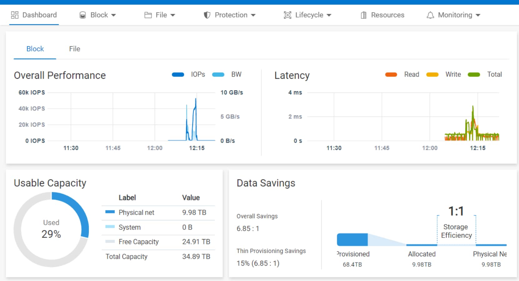
Figure 4.  PowerFlex 4.0 dashboard
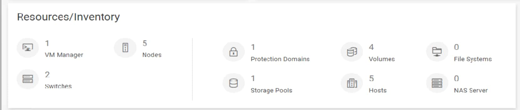
Figure 5.  PowerFlex 4.0 resources/inventory information


Logical architecture

The PowerFlex software-defined infrastructure is configured in a VMware vSphere environment and deployed with a single-layer Hyperconverged Infrastructure (HCI) architecture option. An HCI configuration has both the Storage Data Client (SDC) and Storage Data Server (SDS) configured on each node of the cluster as shown in the following figure. 
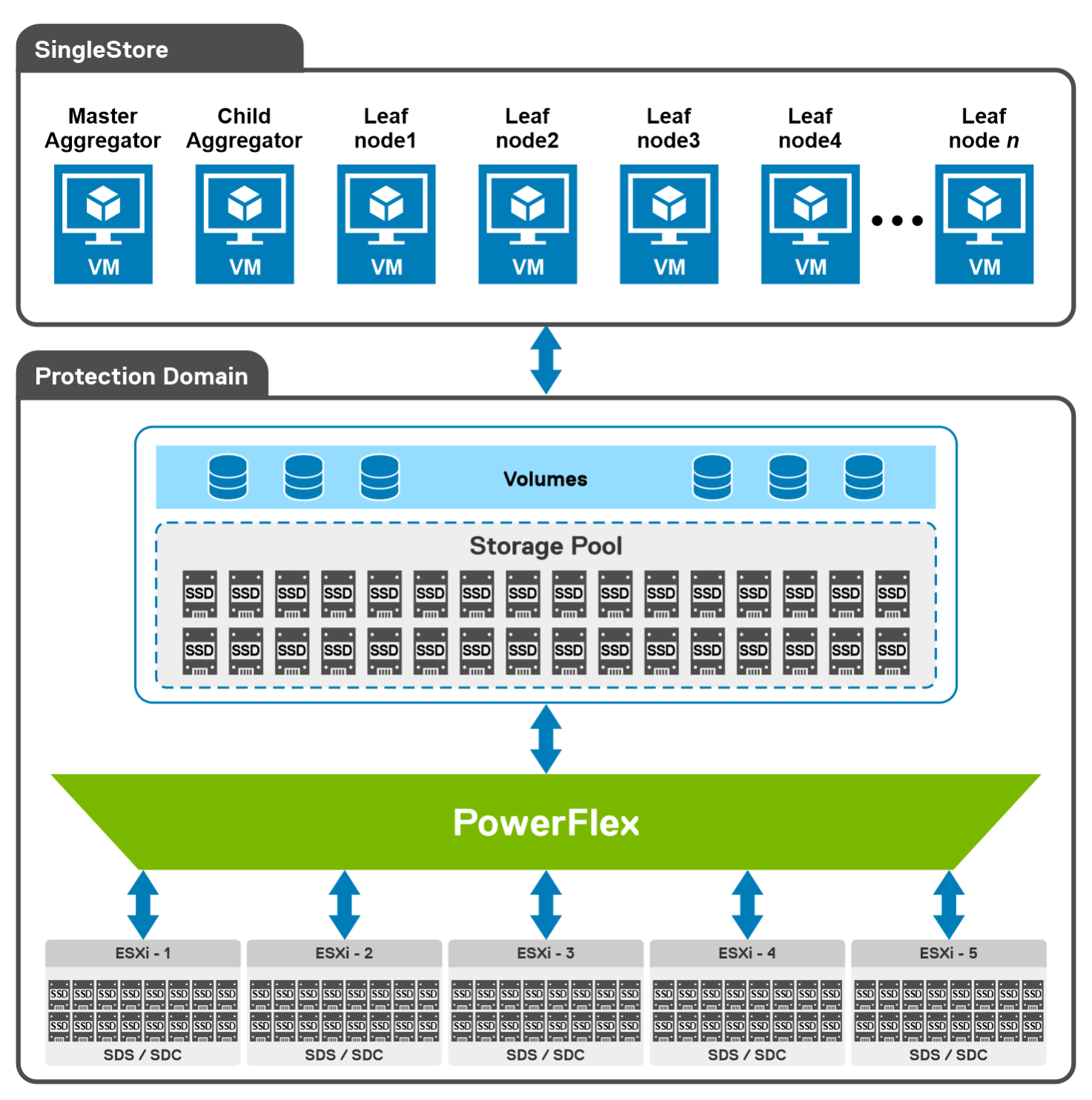
Figure 6.  Logical architecture of SingleStore deployment on PowerFlex

The Storage Data Server (SDS) aggregates the raw local storage in a node and assists as PowerFlex storage. A single protection domain is carved out of the 40 SSD drives on the five PowerFlex HCI nodes. Each host is populated with eight 1.92 TB SSD drives. A single storage pool is configured, and multiple volumes are created to meet the SingleStore needs. These volumes are mapped to the ESXi cluster and added as a datastore. 

The SingleStore Cluster VMs are deployed onto these datastores, which consist of two aggregator and multiple leaf VMs. These are later mapped as disk drives to the SingleStore virtual machines using VMware Paravirtual SCSI (PVSCSI) adapters.

Network design

PowerFlex rack is available in two different network architectures to meet different performance and scaling requirements.

In this solution, we have followed the access and aggregation network architecture for HCI configuration. For more information about network architecture, see the Dell PowerFlex network architecture.

The following figure shows the logical layout of the PowerFlex rack, access, and aggregation with management aggregation architecture:
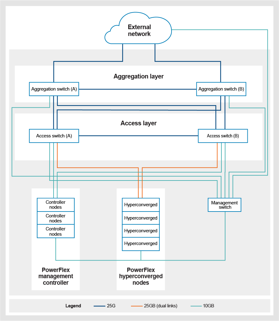
 

                    Figure 7.   PowerFlex network architecture

All nodes are connected to two Dell PowerSwitch S-5248F switches that are configured with VLT to enable interconnectivity and fault tolerance. All nodes are outfitted with two dual-port Mellanox 25 GbE NICs that provide four 25 GB ports on each server. One port from each NIC is connected to one switch and the other port is connected to the second switch. Ports are also NIC teamed to provide high availability.

For standard practices that are outlined for the PowerFlex deployment, dedicated VLANs are used for vMotion, managing the hypervisor, customer network, PowerFlex, and so on. 

SingleStore design

The SingleStore cluster environment that is used for this solution consists of multiple VMs. The implementation divides the server VMs into two broad categories: aggregator and leaf VMs. Each VM type has a configuration that is optimized for its role in the cluster. 

The following table lists the VM definitions and configuration:

Table 2.  VM definitions

VM

Count

Definition

Aggregator

2

An aggregator is a node that routes the queries to the leaves, aggregates intermediate results, and sends the results back to the client. There are two types of aggregators: master and child.

Leaf 

4-8

A leaf is a node that stores a subset of a clusters data. It functions as a storage and compute node. To optimize performance, SingleStore automatically distributes the data across leaf nodes into partitions. Each leaf contains several partitions. 


The following table lists the aggregator and leaf VM details:

Table 3.  SingleStore virtual machine configuration

VM

vCPU

Memory

Disk

Master aggregator

16

128 GB

1 TB

Child aggregator

16

128 GB

1 TB

Leaf

16

128/48 GB

5 TB


SingleStore deployment

Creating VMs

When PowerFlex is installed and configured, the SingleStore is deployed by creating Red Hat Enterprise Linux 7.9 VMs on the PowerFlex nodes. These VMs are configured as SingleStore aggregator and leaf nodes.

Deploying SingleStore

There are multiple ways to deploy the SingleStore cluster. This solution follows the user interface online method:

Step 1: Start the UI

Run the following command on the master aggregator VM. 

sdb-deploy ui

The command displays a link with a secure token that you can use to deploy SingleStoreDB using the UI.

Step 2: Access the UI

Copy and paste the link obtained in Step 1 into a Chrome or Firefox browser to access the UI. Modify the URL by changing the localhost to master aggregator hostname or IP.

Example:http://172.16.0.50:8081#WTgeL0EwX/9h2I+jEroYz3FGWll7Whx2A8Y8ExkvAkE=

For the remaining steps, see Online Installation of SingleStore DB.

After the SingleStore cluster is up and running, use the dashboard to verify the health of the cluster and node details as shown in the following figures:
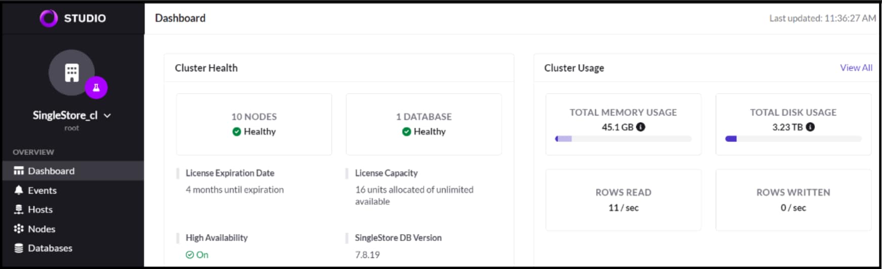
Figure 8.  SingleStore cluster dashboard
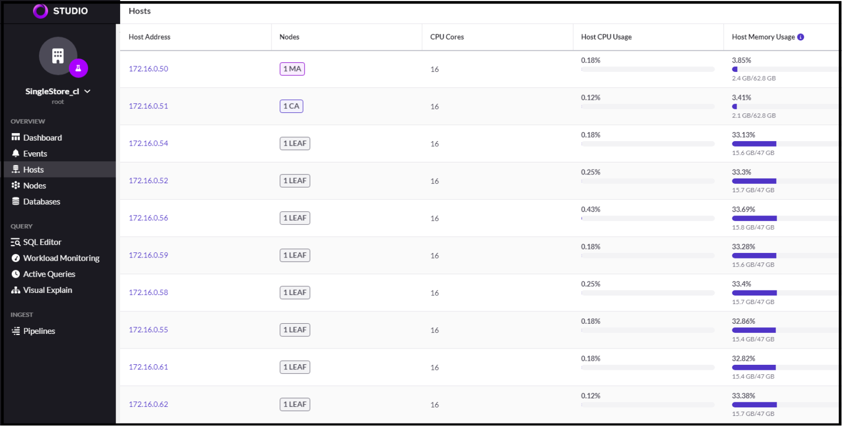
Figure 9.  SingleStore leaf and aggregator nodes


Testing and validation

Overview

The objective of this section is to run industry standard benchmark like TPC-DS queries to determine how SingleStore supports complex queries with the decision support data. The decision support data has been distributed across multiple leaf nodes providing optimal utilization of compute, network, and storage resources.

Workload

Dell used 95 TPC-DS based queries to measure the performance but excluded the following queries: q4, q23-p1, q23-p2, and q67 because they are time consuming and high CPU intensive.

The test runs queries of various operational requirements and complexities. For example, ad hoc, reporting, iterative OLAP, and data mining and is characterized by high CPU and I/O load. For more information about all the 99 queries, see TPC-DS queries.

Test methodologies

The following test methodologies were used:

To generate 3 TB data using dsdgen tool

  1.           Run the following commands to clone the repo and build the dsdgen tool:

sudo yum install gcc make flex bison byacc git

git clone https://github.com/databricks/tpcds-kit.git

cd tpcds-kit/tools

make OS=LINUX

Note: The dsdgen tool generates the data sets for the TPC-DS like benchmark.

  1.           Run the following command once the tool is built:

./dsdgen -scale 3000 -dir /home/tpcdata

To create tables

  1.           Run the following script to create tables:

create-tables.sql

To load tables

  1.           Populate the SingleStoreDB consisting of 24 tables using Load Data commands.

  The following figure shows the total number of tables and row count for each table:
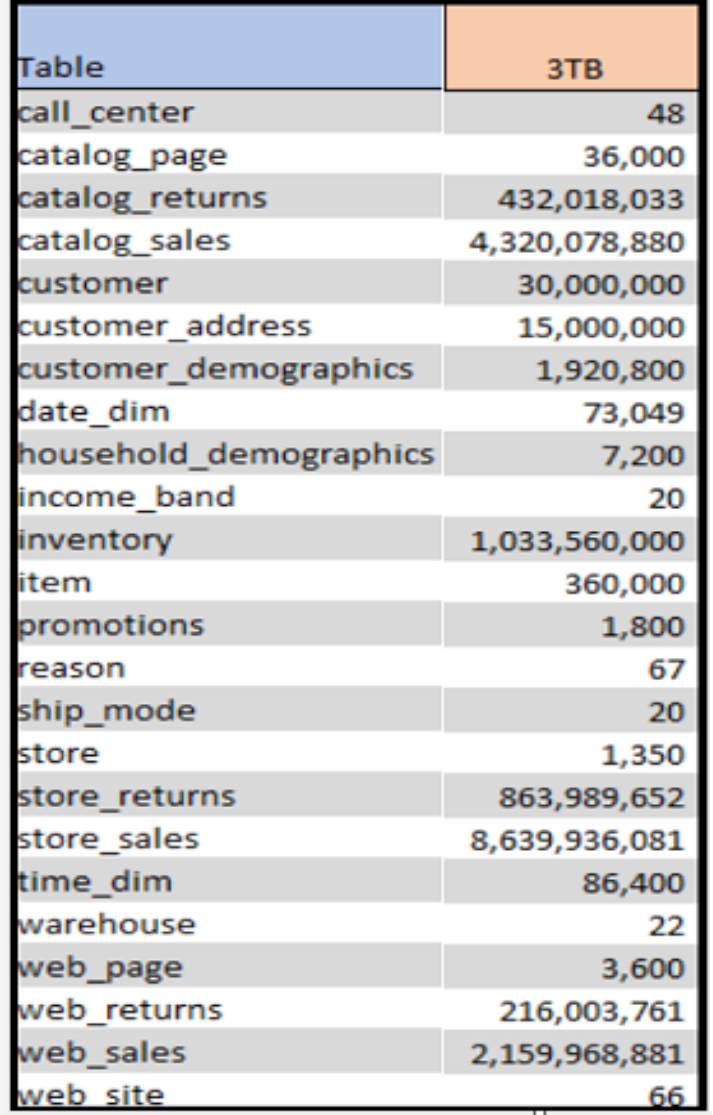
Figure 10.  Table list


Test scenarios

Tests were conducted starting with four leaf nodes. The number of leaf nodes was increased gradually to six and eight to understand the variation in the PowerFlex performance. The workload was evaluated for each scenario and PowerFlex performance metrics were captured in the following table.

Table 4.  Test scenarios


No of leaf nodes

vCPUs per leaf node

Memory per leaf node

Read Max BW

Read Max IOPS

Scenario -1

4

16

128 GB

20.2 GB/s

46.9 K

Scenario -2

6

16

128 GB

21.0 GB/s

67.0 K

Scenario -3

8

16

 48 GB

23.0 GB/s

74.3 K


Note: SingleStore does not recommend overcommitting the vCPUs for the leaf nodes.

Validation results

The following figure shows the Grafana dashboard instance that is captured for eight leaf nodes (16 vCPUs and 48 GB ram). The PowerFlex system could achieve up to 23 GB/s read bandwidth. This validation shows that having more SingleStore leaf nodes results in better performance outcomes. And the flexible scaling capability of PowerFlex helps the customers achieve greater performance results.
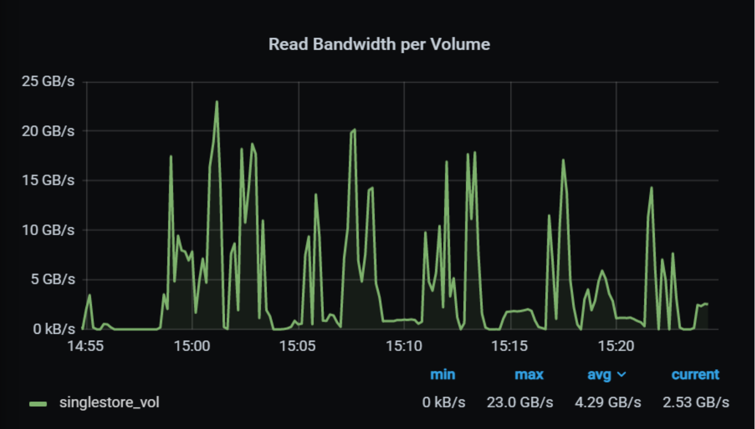
Figure 11.  PowerFlex read bandwidth with eight leaf nodes

The following PowerFlex dashboard shows the overall performance achieved during eight leaf nodes test run.
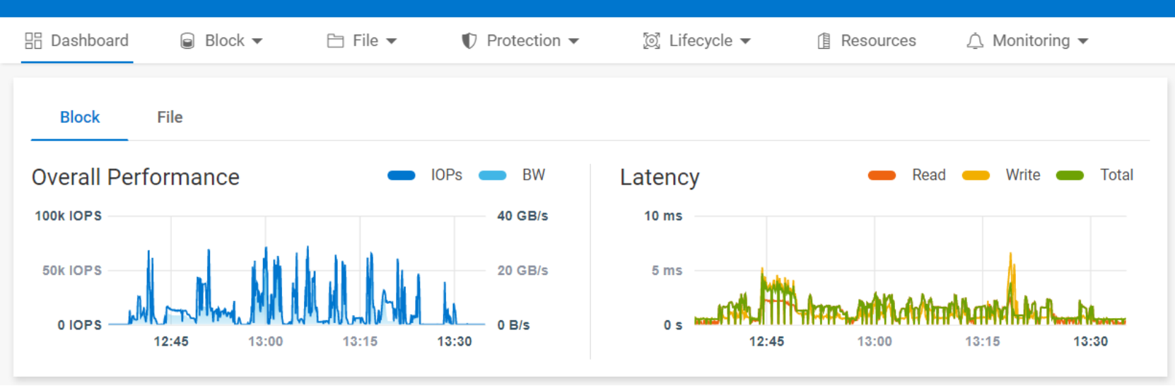
Figure 12.   PowerFlex 4.0 performance dashboard

The current configuration supported the scaling of up to eight leaf node VMs on five PowerFlex HCI nodes. There were no storage bottlenecks for the TPC-DS like workload for decision support queries using industry standard benchmark. The CPU on the worker nodes reached close to 100 percent for some of the queries, indicating that more powerful nodes could enhance the performance.
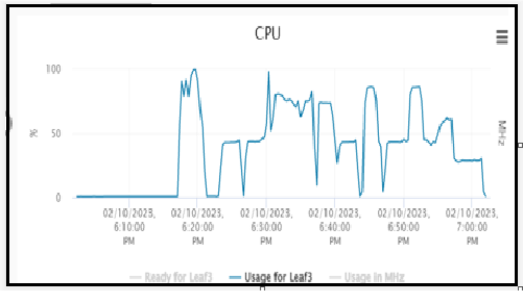
Figure 13.   CPU utilization


Conclusion

Conclusion

This white paper describes how to deploy a SingleStore with PowerFlex software-defined infrastructure as a modern scale-out architecture.

The key advantage of using PowerFlex with SingleStore is the capability to independently aggregate, scale, monitor, and manage components across the stack. This achieves high database performance, using the strengths of both the products. The Leaf nodes distribute data across all nodes to optimize the performance with automated load balancing. You can scale storage I/O and throughput by deploying the SingleStore nodes on PowerFlex. This allows you to have a flexible design that can grow rapidly, with freedom of compute and storage mechanisms.

Appendix

Appendix

This section provides the details of the hardware and software components that are used for the SingleStore deployment on PowerFlex.

Hardware and Software details

The following table describes the PowerFlex components that are used in this solution:

Table 5.  PowerFlex components

PowerFlex component

Configuration

Node

5 x PowerFlex R640

CPU

2 x Intel Xeon Gold 6348 CPU at 2.50 GHz, 20 cores 

Memory

24 x 16 GB DDR-4

NIC

2 x Mellanox ConnectX-4 LX 25 GbE SFP Adapter

Storage

Dell HBA330 controller 8 x 1788 GB SATA SSD

PowerFlex version

4.0

SingleStoreDB version

7.8

Best practices

Best practices

This section outlines the performance best practices that are followed in this solution.

PowerFlex rack best practices

The following best practices are recommended for the PowerFlex rack:

  • Minimum number of nodes for production workloads should be eight.
  • Homogenous node types should be used for predictable performance.
  • Ensure that the maximum number of devices in a storage pool is 300.
  • Ensure that the passwords are changed for all the default accounts.
  • Ensure that the communication is secure - HTTPS (TCP port 443) - to remotely access the PowerFlex nodes.
  • Ensure that the PowerFlex rack is compliant to an RCM.

PowerFlex best practices

The following best practices are recommended for the PowerFlex system:

  • Configure the high-performance profile for MDM, SDS, and SDC.
  • Disable the Read Flash Cache and Read RAM cache for all flash clusters. 
  • Sometimes, increasing the device queue depth value to 256 can improve I/O concurrency.
  • Create thick provisioned volumes.

Note: The parameters can be set from the PowerFlex CLI.

  •  Run the following command to increase the SDS threads to twelve:

scli --set_performance_parameters --all_sds --tech --sds_number_os_threads 12


PowerFlex networking and server nodes best practices

The following best practices are recommended for the PowerFlex networking and server nodes:

  • Change the grub template of all Storage Data Server (SDS) nodes to disable Intel CPU P-State and enable C-State.
  • Enable block multiqueue queueing mechanism in all the SDS nodes. The Multi-Queue Block I/O queueing mechanism enables fast storage devices to achieve a huge number of I/O operations per second (IOPS). This can be achieved through queueing and submitting I/O requests to block devices simultaneously, benefiting from the parallelism offered by the modern storage devices such as SSDs.
  • For ESXi compute-only nodes, using esxcli, set the Number of outstanding IOs with competing worlds to 256 for all the volumes provisioned from PowerFlex. Increasing this value from default 32 to 256 enhances the performance.
  • Ensure that the server performance profile is set to High Performance.
  • Use jumbo frames (9000 Bytes MTU) throughout the networking infrastructure such as VMware vSwitches, VMkernel ports, and physical switches.

References