Google Distributed Cloud Virtual with Dell PowerFlex and Data Protection using PowerProtect Data Manager
Executive Summary
Executive summary
Introduction
Revisions
Audience
Terminology
We value your feedback
Product overview
PowerFlex family
PowerFlex software-defined infrastructure enables broad consolidation across the data center, encompassing almost any type of workload and architecture. The software-defined architecture offers automation and programmability of the complete infrastructure and provides scalability, performance, and resiliency to enable effortless adherence to stringent workload SLAs.
The PowerFlex family provides a foundation that combines compute and high-performance storage resources in a managed unified fabric. PowerFlex comes in flexible deployment options (rack, appliance, or custom nodes and in the public cloud) that enables independent (two-layer), HCI (single-layer), or mixed architectures. PowerFlex is ideal for high-performance applications and databases, building an agile private/hybrid cloud, or consolidating resources in heterogeneous environments.
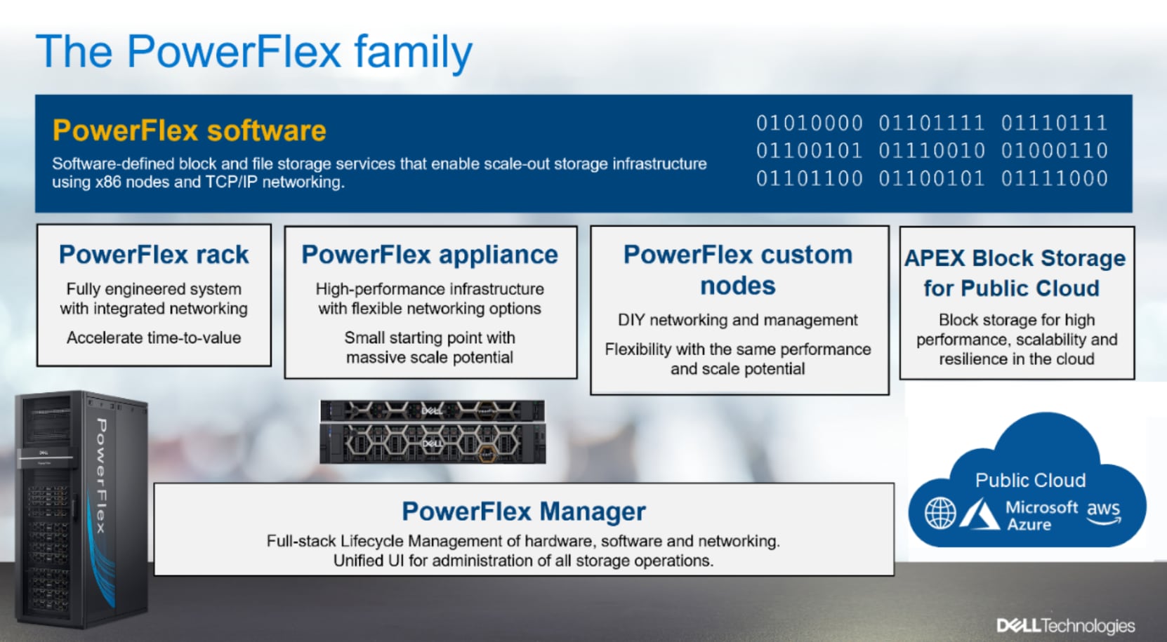
Figure 1. PowerFlex family
PowerFlex software components
Software is the key differentiation in the PowerFlex offering. PowerFlex software components not only provide software-defined storage services, but also help simplify infrastructure management and orchestration. This software enables comprehensive IT Operational Management (ITOM) and Life Cycle Management (LCM) capabilities that span compute as well as storage infrastructure, from BIOS and Firmware to nodes, software, and networking.
PowerFlex
PowerFlex is the software foundation of PowerFlex software-defined infrastructure. It is a scale-out block and file storage service that is designed to deliver flexibility, elasticity, and simplicity with predictable high performance and resiliency at scale.
PowerFlex Manager
PowerFlex Manager is the software component in the PowerFlex family that enables ITOM automation and LCM capabilities for PowerFlex systems. Starting with PowerFlex 4.0, the unified PowerFlex Manager brings together three separate components that are used in previous releases – PowerFlex Manager, the core PowerFlex UI, and the PowerFlex gateway. The new PowerFlex UI runs in Kubernetes and embraces a modern development framework.
PowerFlex file services
PowerFlex File Controllers, also known as File Nodes, are physical nodes that enable PowerFlex software defined File Services. They host the NAS Servers, which in turn host the tenant namespaces and file systems, mapping PowerFlex volumes to the file systems presented by the NAS Servers. All major protocols are supported, such as NFS, SMB/CIFS, FTP, and NDMP. PowerFlex file service is supported from PowerFlex 4.0.
PowerFlex with NVMe over TCP (NVMe/TCP)
NVMe is a family of open specifications that defines an industry standard for both a logical interface and a communication protocol for accessing block storage across an internal PCIe fabric or through external fabrics such as TCP/IP and FC. NVMe is designed to take advantage of the internal parallelism and low latency inherent in flash-based media SSDs.
NVMe/TCP is an extension of the NVMe base specification that defines the binding of the NVMe protocol to message-based fabrics using TCP. By binding the NVMe protocol to TCP, NVMe/TCP enables the efficient end-to-end transfer of commands and data between NVMe hosts and NVMe controller devices by any standard Ethernet-based TCP/IP networks.
From PowerFlex release 4.x onwards, support for NVMe/TCP has been added for on-premises deployment with the introduction of a new Storage Data Target (SDT) component installed in the storage layer. The NVMe initiator in the operating system or hypervisor communicates with the SDT, which then communicates with the Storage Data Server (SDS). The NVMe initiator is part of the kernel of the application host operating system or hypervisor.
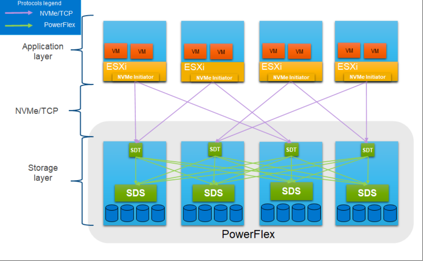
Figure 2. PowerFlex with NVMe/TCP
For more information, see PowerFlex with NVMe over TCP.
PowerFlex deployment architectures
PowerFlex software-defined infrastructure excels in deployment flexibility. PowerFlex can be deployed in a two-layer (independent compute and storage layers), single-layer (Hyperconverged Infrastructure, or HCI), or a mixture of the two architectures (Mixed).
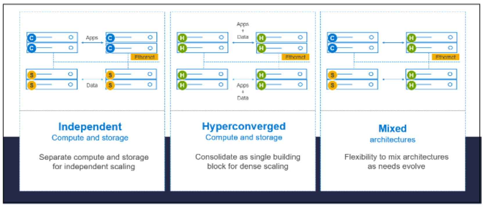
Figure 3. PowerFlex deployment architectures
Independent architecture
In an independent architecture or two-layer architecture, some nodes provide storage capacity for data in applications, while other separate and independent nodes provide compute resources for applications and workloads. Compute and storage resources can be scaled independently by adding nodes to the cluster while it remains active. This separation of compute and storage resources helps to minimize software licensing costs in certain situations. This architecture can be ideal for high-performance databases and application workloads.
Hyperconverged architecture
In an HCI architecture, each node in the cluster contributes storage and compute resources simultaneously to the applications and workloads. This architecture allows you to scale your infrastructure uniformly with building blocks that add both storage and compute resources. This architecture is appropriate for data center and workload consolidation.
Mixed architecture
A mixed architecture is a combination of both the HCI and Independent architectures. As shown in Figure 3 there are some storage only nodes, compute only nodes, and HCI nodes as a part of the same PowerFlex cluster. This is a desirable architecture when working with an existing compute infrastructure and adding high-performance software-defined infrastructure. This can also be a starting point for a two-layer deployment design as external workloads are migrated to PowerFlex.
PowerFlex consumption options
PowerFlex rack
PowerFlex rack is a software-defined infrastructure platform that delivers flexibility, elasticity, and simplicity with predictable performance and resiliency at scale by combining compute as well as high-performance storage resources in a managed unified network. This rack-based engineered system, with integrated networking, enables customers to achieve the scalability and management requirements of a modern data center.
PowerFlex appliance
PowerFlex appliance is a PowerEdge server which has been configured to be a node in a software-defined infrastructure deployment that runs PowerFlex software components. This offering allows customers the flexibility and savings to bring their own compatible networking.
PowerFlex custom nodes
PowerFlex Custom Nodes are validated server building-blocks configured for use with PowerFlex. They are available with thousands of configuration options and are available for customers who prefer to build their own environments.
Dell APEX Block Storage for Public Cloud
PowerFlex software is also available in the public cloud as Dell APEX Block Storage for Public Cloud. It offers the same on-premises benefits of high-performance, linear scalability, and high resilience as in cloud. It also adds cloud-specific benefits, such as large volume sizes, extreme performance based on NVMe drives, and predictable scalability. The Dell APEX Block Storage self-healing architecture simplifies and increases the availability of infrastructure. It is designed to remain running even when it encounters failures. With fast rebuilds, Dell APEX Block Storage recovers rapidly from failures and keeps operating, without degrading performance or compromising availability. You can also extend this availability and configure it to protect your application availability across multiple availability zones.
PowerFlex CSI/CSM
An important component outside of PowerFlex that enables a flexible consumption model for Kubernetes is the PowerFlex CSI driver, developed as a part of the Dell Kubernetes strategy. After loading the CSI driver for PowerFlex into Kubernetes, it can be used to provision persistent volumes from the underlying PowerFlex storage resource. If the Kubernetes deployment is running low on PowerFlex storage resources, you can add PowerFlex storage nodes to increase the system capacity and performance.
The CSI driver connects the PowerFlex system and Kubernetes deployments. It is a storage broker which dynamically provisions volumes from PowerFlex through the PowerFlex API gateway to the Kubernetes cluster. Once the volume is available on PowerFlex, it is immediately mapped to the requesting pod. If a pod is destroyed or rescheduled, the CSI plug-in ensures that the volumes are remapped upon rescheduling of that pod.
- Customers running Kubernetes clusters on PowerFlex use the Dell Container Storage Modules (CSM), which extend the CSI driver capabilities. These modules:
- Provide enterprise storage capabilities to Kubernetes for cloud-native stateful applications.
- Reduce management complexity, so that developers can independently use enterprise storage with ease and automate daily operations.
- Extends storage functionality and capabilities beyond using the CSI driver alone.
These modules include snapshot, observability, authorization, application mobility, and resiliency.
PowerFlex supports multiple operating systems, different deployment options on-premises and public cloud deployment model (available in AWS and Azure). PowerFlex is validated with the leading Kubernetes distributions as shown in the following figure:
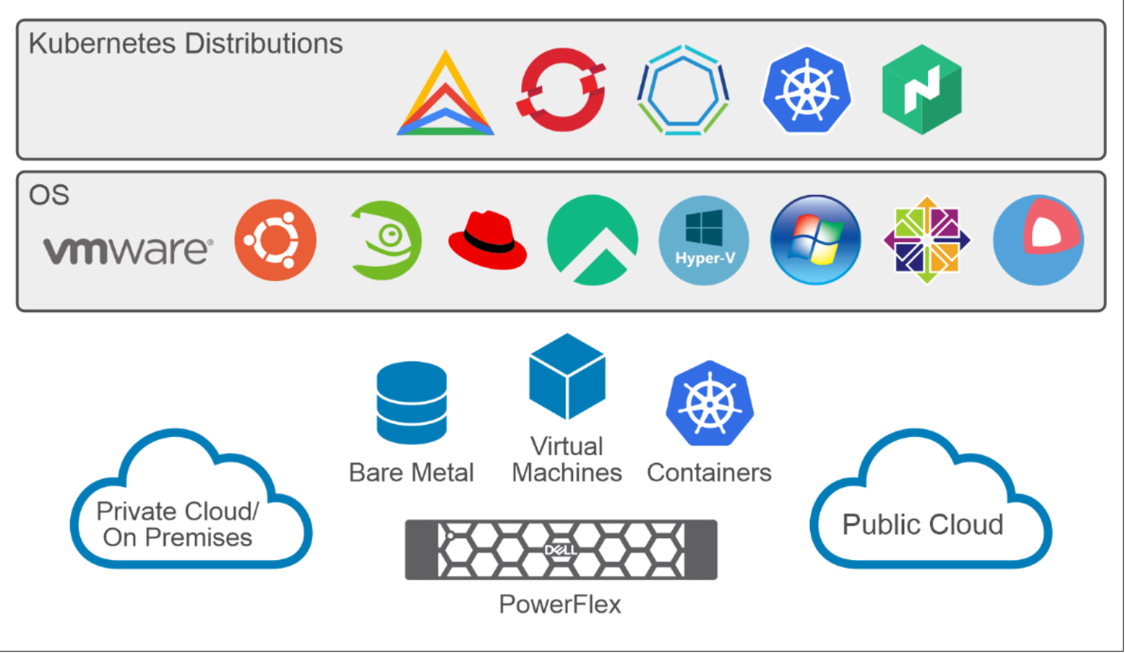
Figure 4. PowerFlex for different Kubernetes distributions
GDC Virtual on PowerFlex: Bare metal deployment
Overview
GDC Virtual on PowerFlex deployment models
Logical architecture of PowerFlex two-layer deployment
The following diagram shows the logical architecture of the GDC Virtual cluster that is deployed on a two-layer PowerFlex cluster setup. In this solution, there are four nodes that are dedicated for storage-only (SDS) and three nodes that are dedicated for compute-only (SDC). A single protection domain is created from the four storage nodes, and a single storage pool is created within this protection domain from which persistent storage volumes can be provisioned for attachment to Kubernetes pods. This architecture is suitable for environments where the storage and compute capacities are decoupled, such as high-performance applications, or for rapidly growing storage capacity requirements.
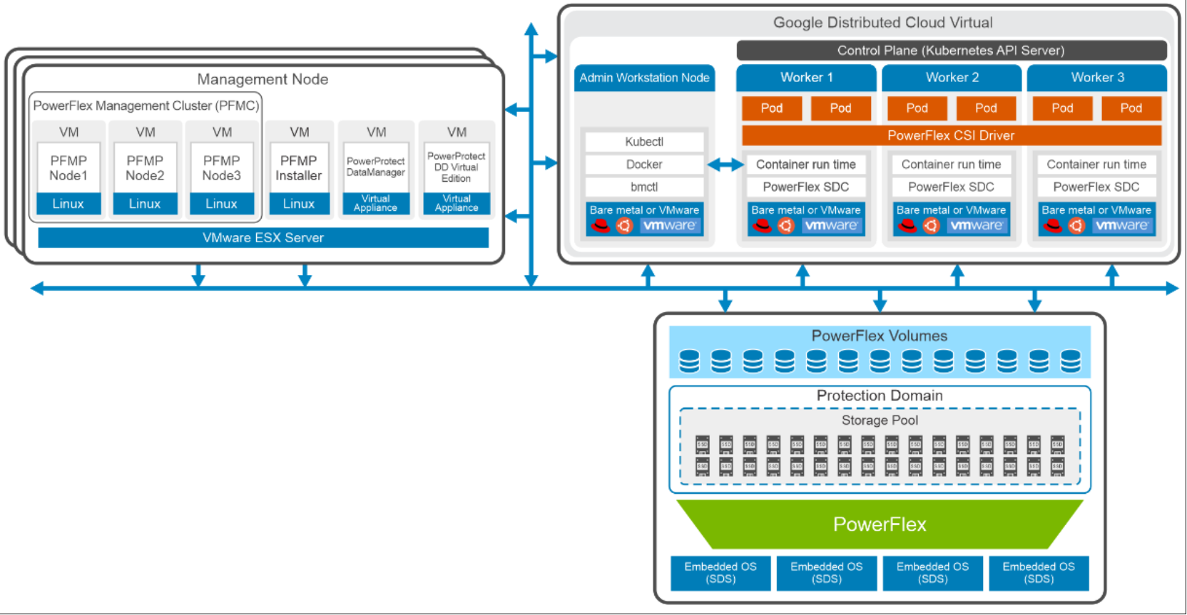
Figure 5. Logical architecture of PowerFlex two-layer deployment and GDC Virtual cluster
Deploying GDC Virtual on Bare metal
Dell PowerFlex CSI on the GDC Virtual cluster
PostgreSQL on Kubernetes
Brief Introduction to PostgreSQL
Deploying PostgreSQL application on PowerFlex system
After the GDC Virtual cluster has been installed and registered, applications can be deployed using Google Cloud Console. In this solution, a PostgreSQL database application with persistent volume (using the PowerFlex storage class) is dynamically provisioned.
Deploying Postgres
- Log in to the Google Cloud Platform
- Select Kubernetes Engine > Applications as shown in the following figure:
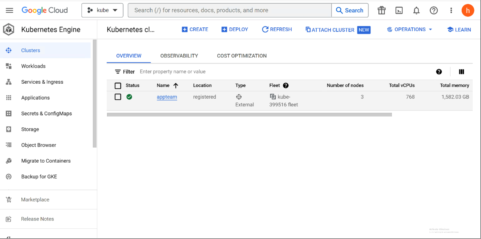
Figure 6. Overview of Kubernetes cluster highlighting the number of nodes, total memory, and total vCPUs
The following figure shows the details of the nodes:
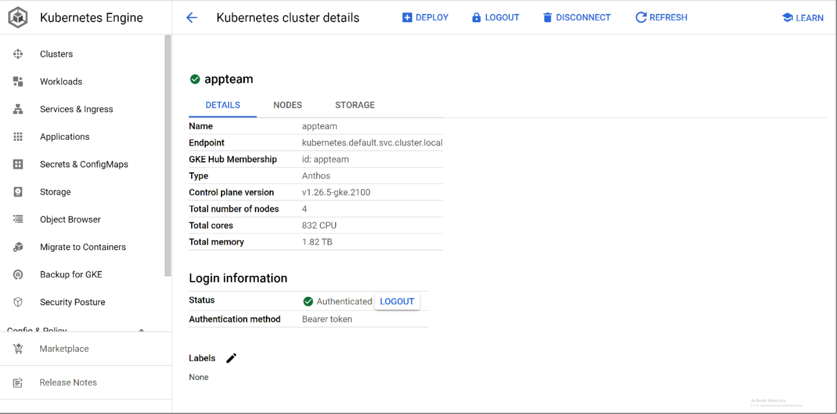
Figure 7. Details of Kubernetes cluster deployed on the nodes
- To deploy the applications, go to the Applications tab > Deploy from Marketplace as shown in the following figure:
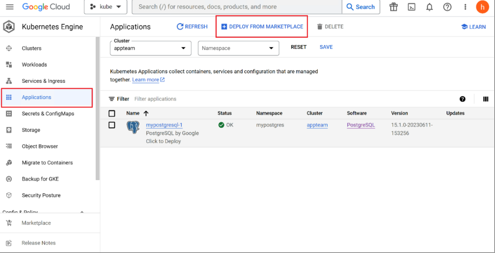
Figure 8. Application deployment on the cluster
- Search for PostgreSQL Server as shown in the following figure:
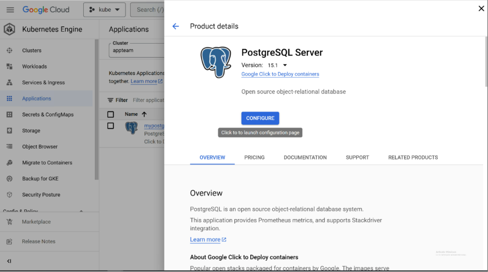
Figure 9. PostgreSQL selection in the Cloud Console
- Specify the required fields such as namespace name and app instance name. Select the PowerFlex storage class and specify the size of the volume to be created for Postgres and click deploy.
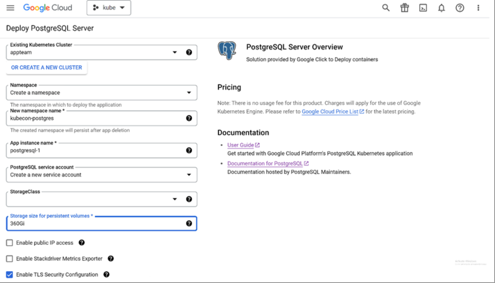
Figure 10. Configuring PostgreSQL with the required details
- A 360Gb persistent volume is created internally in PowerFlex and attached to the Postgres database application under a new namespace that is specified in configuration as shown in the following figures:
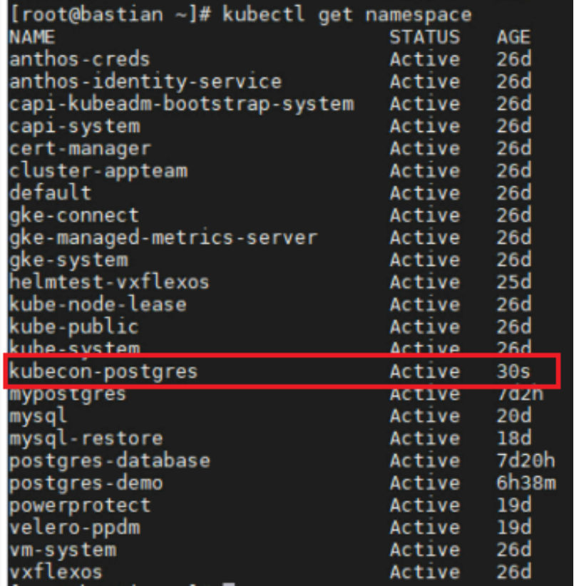
Figure 11. New namespace created in the cluster

Figure 12. Name of the Persistent Volume used by Postgres
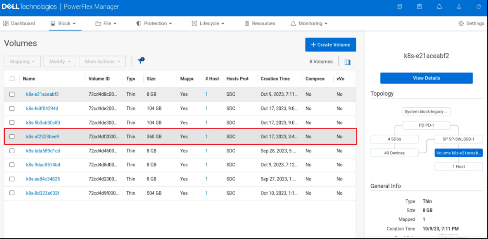
Figure 13. Block Volume created in PowerFlex
The following figure shows the verification of the Postgres database in the cluster:
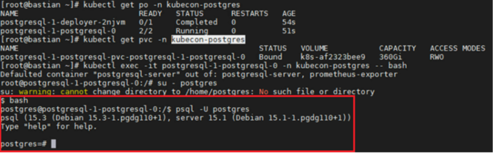
Figure 14. Verification of Postgres database in the cluster
Data Protection with PowerProtect Data Manager
Data Protection with PowerProtect Data Manager
PowerProtect Data Manager protects Kubernetes workloads and ensures that the data is protected and recoverable. PowerProtect Data Manager can be deployed using an Open Virtualization Appliance (OVA) or a machine image and is integrated with PowerProtect DD series appliances as protection storage for backups. In this solution, PowerProtect Data Manager and PowerProtect DD Virtual Edition (DDVE) is deployed on Management Node.
In addition to being deployable stand-alone, PowerProtect Data Manager is available as an integrated Dell PowerProtect Data Manager appliance. The PowerProtect Data Manager appliance (DM5500) offers an integrated data protection platform that combines storage protection with PowerProtect Data Manager software and cloud readiness - all in a single appliance.
PowerProtect Data Manager can be integrated with GDC Virtual (on-premises) clusters through Kubernetes APIs to discover protectable resources such as namespaces and PVCs. Data Manager discovers the Kubernetes clusters using the IP address or FQDN. PowerProtect Data Manager uses the discovery service account and the token kubeconfig file to integrate with kube-apiserver.
The following high-level architecture diagram shows the data protection for GDC Virtual cluster with PowerProtect Data Manager:
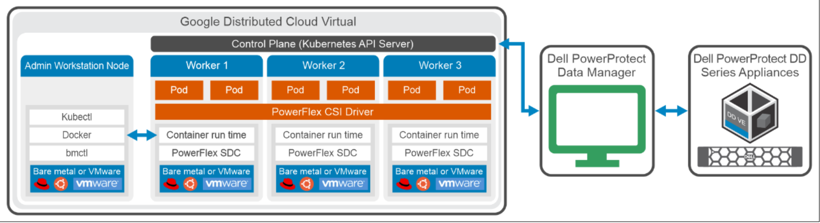
Figure 15. High level architecture diagram of the GDC Virtual cluster data protection with PowerProtect Data Manager
Integrating GDC Virtual cluster with PowerProtect Data Manager
PowerProtect Data Manager can be integrated with the GDC Virtual cluster by directly connecting to the control plane of the GDC Virtual cluster. Kubernetes uses persistent volumes to store persisted application data. Persistent volumes are created on external storage devices and then attached to a particular pod using PVCs. PVCs are included along with other namespaces in Data Manager backup and recovery operations. In this solution, PowerFlex is the default storage class for the Kubernetes cluster workloads that are integrated through the PowerFlex CSI driver.
Once the Kubernetes cluster is added as an asset source in PowerProtect Data Manager and discovery is complete, the associated namespaces are available as assets for protection. PowerProtect Data Manager protects two types of Kubernetes cluster assets: Namespaces and PersistentVolumeClaims (PVCs).
During the discovery process, Data Manager creates the following namespaces in the cluster:
- Velero-ppdm: This namespace contains a Velero pod to back up metadata to target storage. It performs PVC snapshot and metadata backup if VMware cloud native storage is configured.
- PowerProtect: This namespace contains a PowerProtect controller pod to drive persistent volume claim snapshots and backups. It sends the backups to the target storage using dynamically deployed cProxy pods.
Adding GDC Virtual cluster as an asset source
The PowerProtect Data Manager UI is used to enable, add, and register the Kubernetes asset source for the protection of assets.
Enable the asset source as follows:
- From the PowerProtect Data Manager UI, go to Infrastructure > Asset Sources, and click the + icon to display the New Asset Source tab.
- In the New Asset Source window, click Enable Source in the Kubernetes section.
To protect the Kubernetes environment with PowerProtect Data Manager, add the GDC Virtual cluster as an asset source. Namespaces are then automatically discovered as assets for data protection operations. The following figure shows the field details of a Kubernetes cluster:
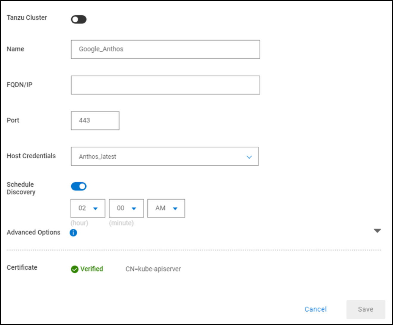
Figure 16. Adding Kubernetes cluster
Specify the Kubernetes cluster attributes as follows:
- Name: Kubernetes cluster name to be displayed in asset sources list
- Address: FQDN or IP address of the Kubernetes API server
- Port: Port to use for communication when the default port, 443, is not used.
Note: The use of any port other than 443 or 6443 requires opening the port on PowerProtect Data Manager.
- Host credentials: Select an existing set of credentials or select Add Credentials to add the service account token for the Kubernetes cluster.
The service account must have the following privileges:
- Get/Create/Update/List CustomResourceDefinitions
- Get/Create/Update ClusterRoleBinding for 'cluster-admin' role
- Create/Update 'powerprotect' namespace
- Get/List/Create/Update/Delete/List
- Get/List/Create/Update/Delete all kinds of resources inside the 'powerprotect' namespace
- Get/List/Watch all namespaces in the cluster and PV, PVC, storageclass, deployments, and pods in all these namespaces
Note: The admin-user service account in the kube-system namespace contains all the privileges. The token of this account can be used directly or an existing similar service account. Alternatively, create a service account that is bound to a cluster role that contains these privileges and provide the token of this service account. For more information, see the PowerProtect Data Manager Kubernetes User Guide.
When you add a GDC Virtual cluster, the cluster information appears in the table, and automatic discovery of the namespace assets is initiated as shown in the following figure:
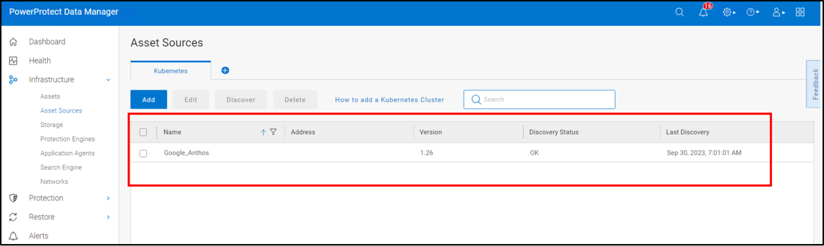
Figure 17. Kubernetes asset sources window
When the discovery is successful, the namespace assets appear as assets in the Kubernetes tab in the Assets window as shown in the following figure:
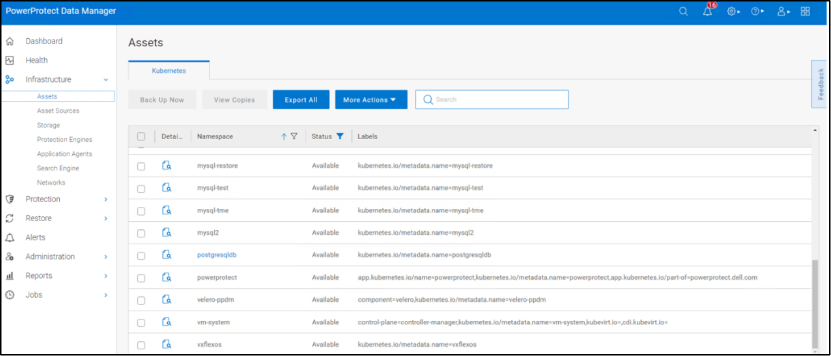
Figure 18. Kubernetes assets window
Protection policy for protecting the namespaces and PVCs
Protection policy for protecting the namespaces and PVCs
Protection policies define sets of objectives that apply to specific periods of time. These objectives drive configuration, active protection, and copy-data-management operations that satisfy the business requirements for the specified data. Each plan type has its own set of user objectives. Users with the system admin role can create protection policies.
PowerProtect Data Manager provides the following options when creating a Kubernetes cluster protection policy:
- Crash Consistent: Select this type for point-in-time backup of namespaces.
- Exclusion: Select this type if there are assets within the protection policy to exclude from data protection operations.
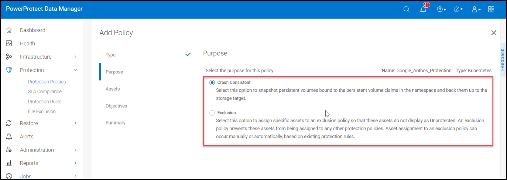
Figure 19. PowerProtect Data Manager policy configuration window - specifying policy purpose
You can also select namespaces and associated PVCs statically or dynamically for inclusion or exclusion in protection policies, along with schedules, retention, and other protection operations as shown in the following figure:
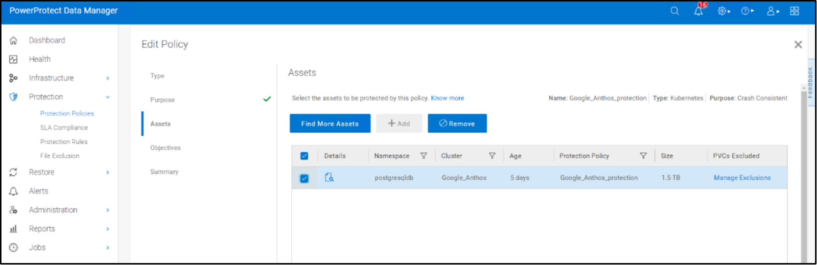
Figure 20. PowerProtect Data Manager policy configuration window – Specifying assets to be protected.
Performing backup of namespaces and PVCs on a GDC Virtual Cluster
Apart from the scheduled backup option, PowerProtect Data Manager supports the option to perform manual backups.
For example, a sample PostgreSQL application is deployed on the GDC Virtual Kubernetes cluster with the namespace postgresqldb. The namespace is composed of a PostgreSQL pod, as shown in the following figure:
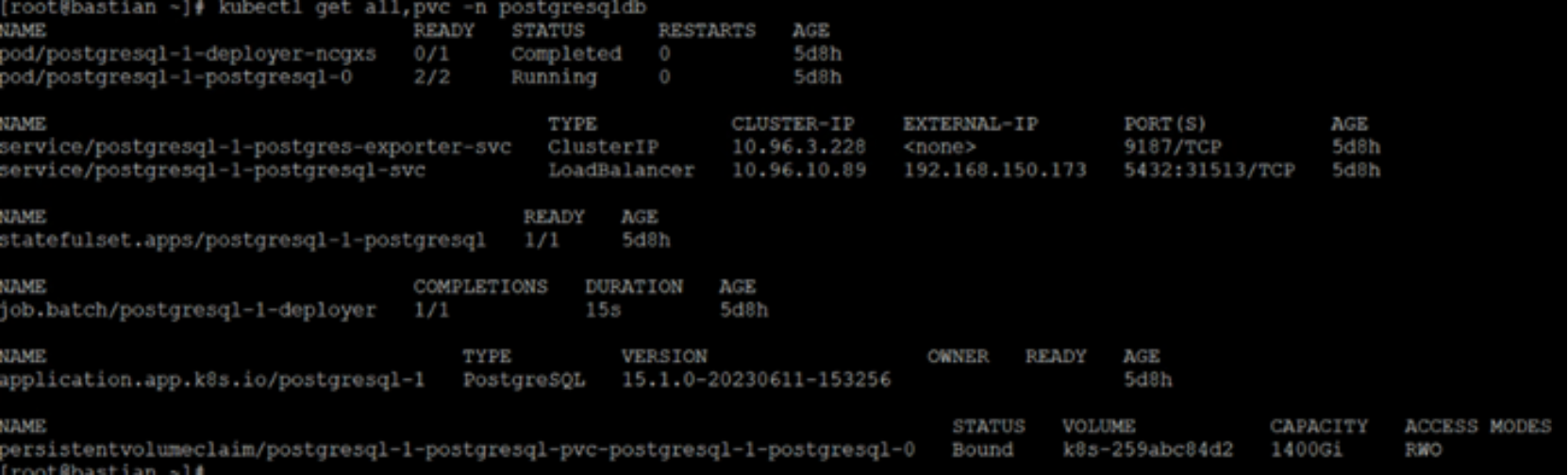
Figure 21. PostgreSQL application pod in postgresqldb namespace
A sample database been created on the PostgreSQL application pod belonging to namespace postgresqldb as shown in the following figure:
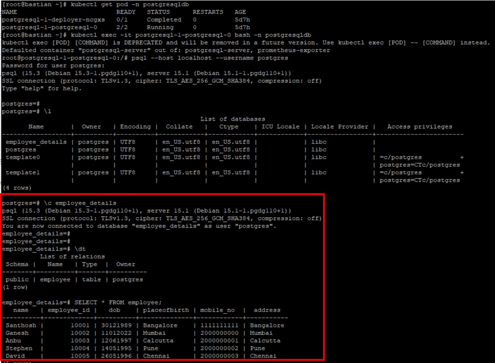
Figure 22. Sample database and table on PostgreSQL application pod
After creating the namespace, backup the namespace postgresqldb and the respective PVCs with PowerProtect Data Manager.
The following figure shows the protection job that is completed successfully for the namespace postgresqldb:
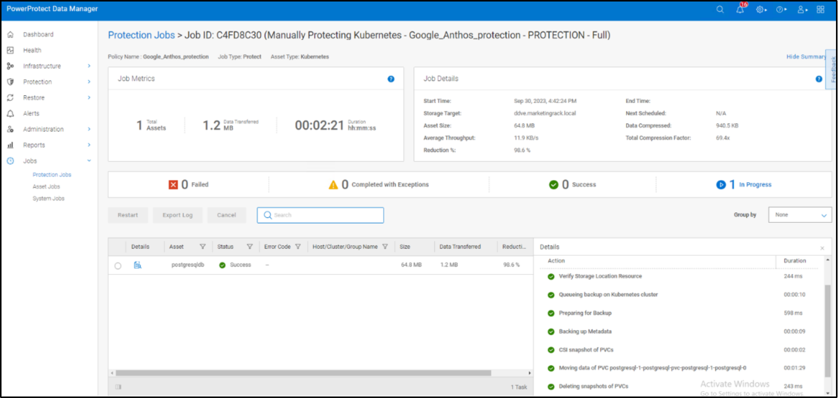
Figure 23. Protection job that is completed successfully for the namespace postgresqldb
The following figure shows the protection copy available for the namespace postgresqldb:
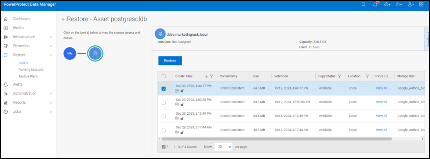
Figure 24. PowerProtect Data Manager asset window displaying the available protection copy
Restoring the namespaces and PVCs on a GDC Virtual cluster
After assets are protected under the Kubernetes cluster protection policy, a restore of namespace and PVCs can be done from individual namespace backups using the following recovery options:
- Restore to original namespace: Restore to the original namespace on the original cluster.
- Restore to a new namespace: Create a namespace and restore to this location on the original cluster or a different cluster.
- Restore to existing namespace: Restore to an existing namespace in the original cluster or a different cluster.
In the following figure shows a sample restore. The data and PVCs that are backed up within the original namespace postgresqldb are restored to the new namespace postgresqldb-restore.
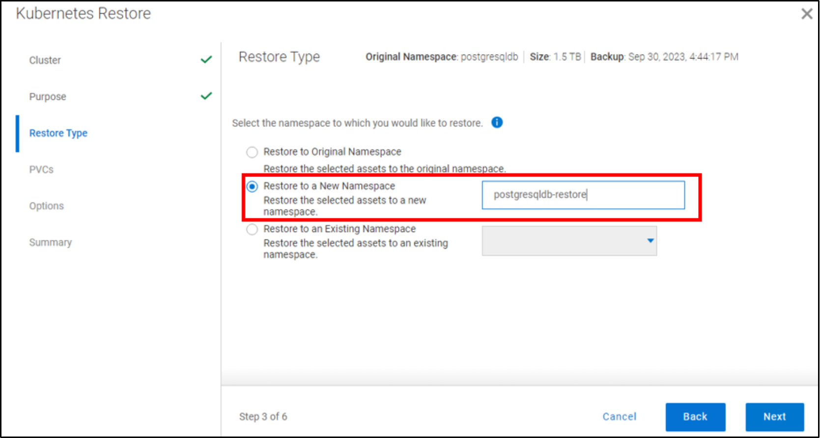
Figure 25. Restore Type window
The following figure shows the PVCs for a restore:
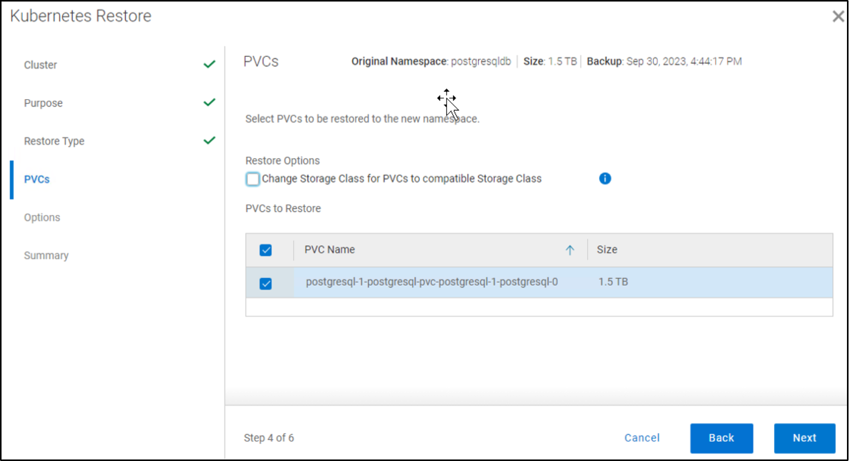
Figure 26. Selecting PVCs for restore
The following figure shows the restore summary:
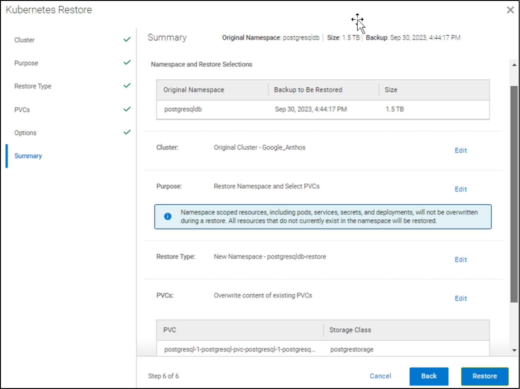
Figure 27. Restore summary
The following figure shows that the restore job is completed successfully:
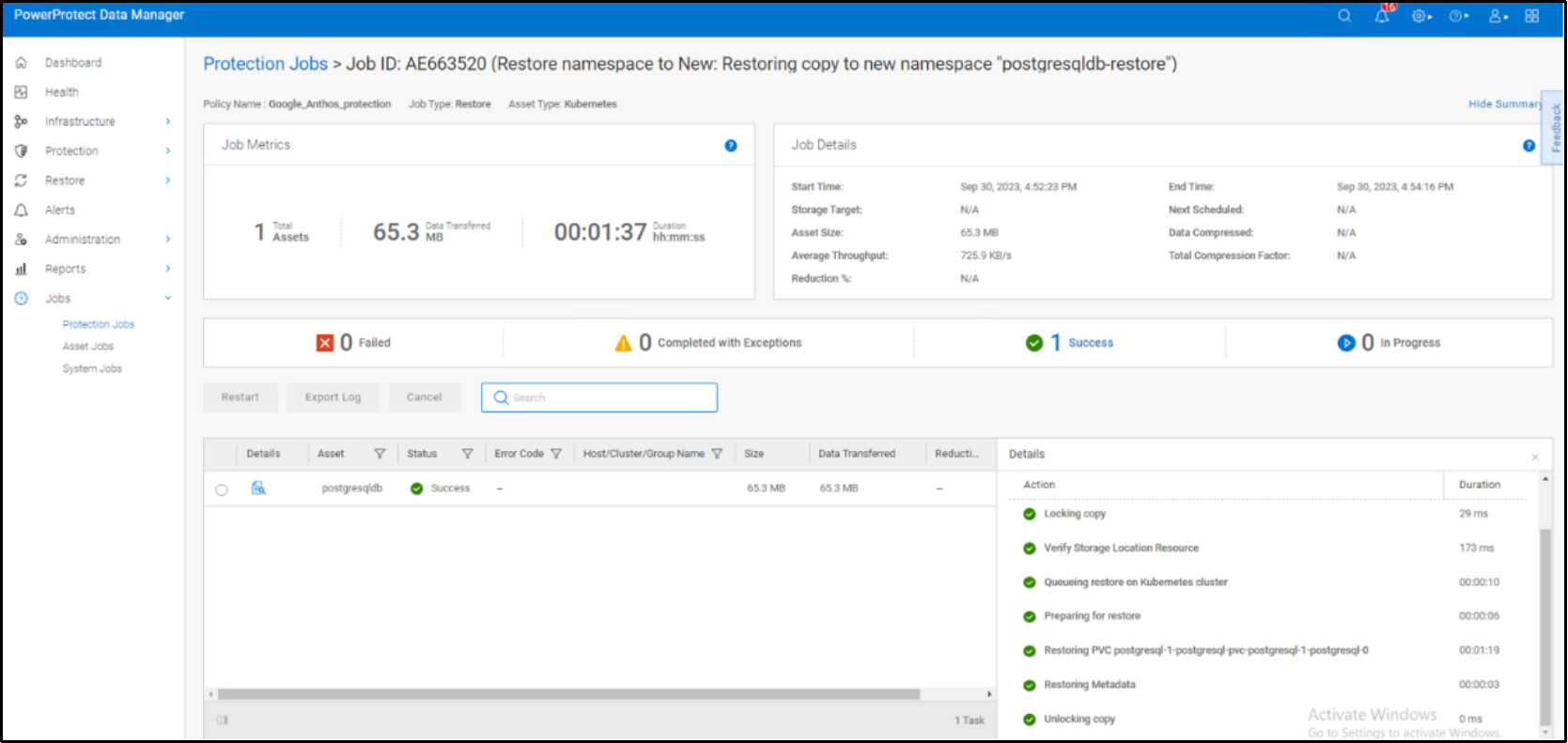
Figure 28. PowerProtect Data Manager restore job summary
The following figure shows that the new namespace postgresqldb-restore was created successfully on the GDC Virtual cluster during the restore:
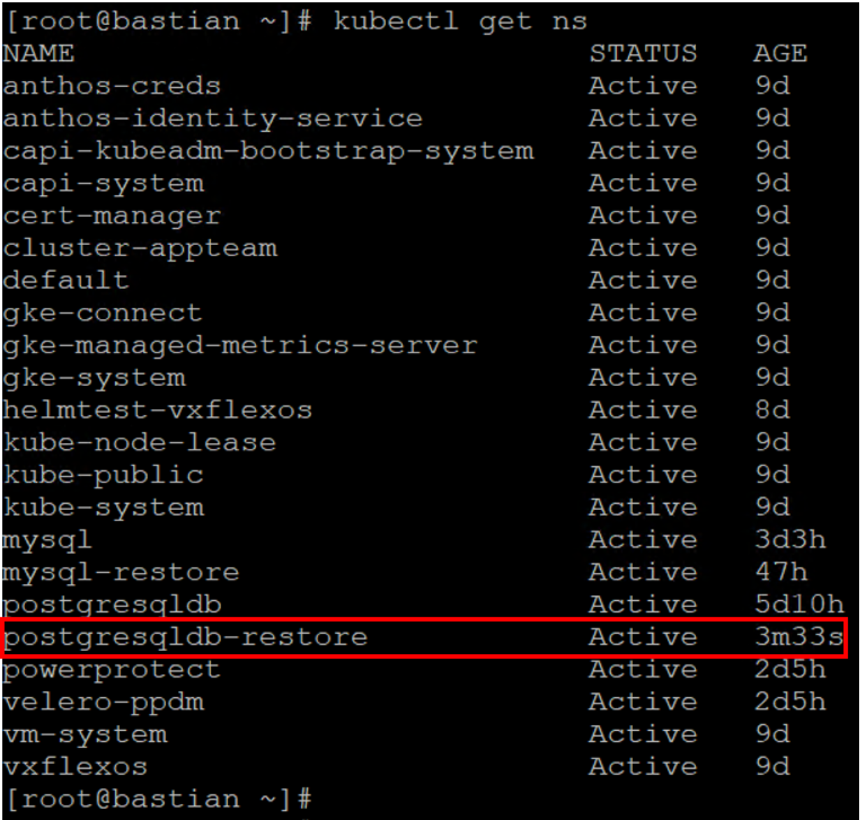
Figure 29. New namespace postgresqldb-restore created on the cluster
The following figure shows that the PostgreSQL application pod has been successfully restored to the new namespace postgresqldb-restore:
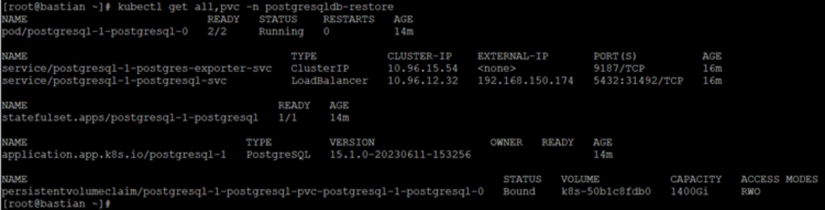
Figure 30. Restored namespace postgresqldb-restore details
The database employee_details and the table that was created on the PostgreSQL application pod belonging to the namespace postgresqldb are now available with the restored namespace postgresqldb-restore.
The following figure shows confirmation of the successful backup and recovery of namespaces and PVCs that are available in the GDC Virtual cluster using PowerProtect Data Manager.
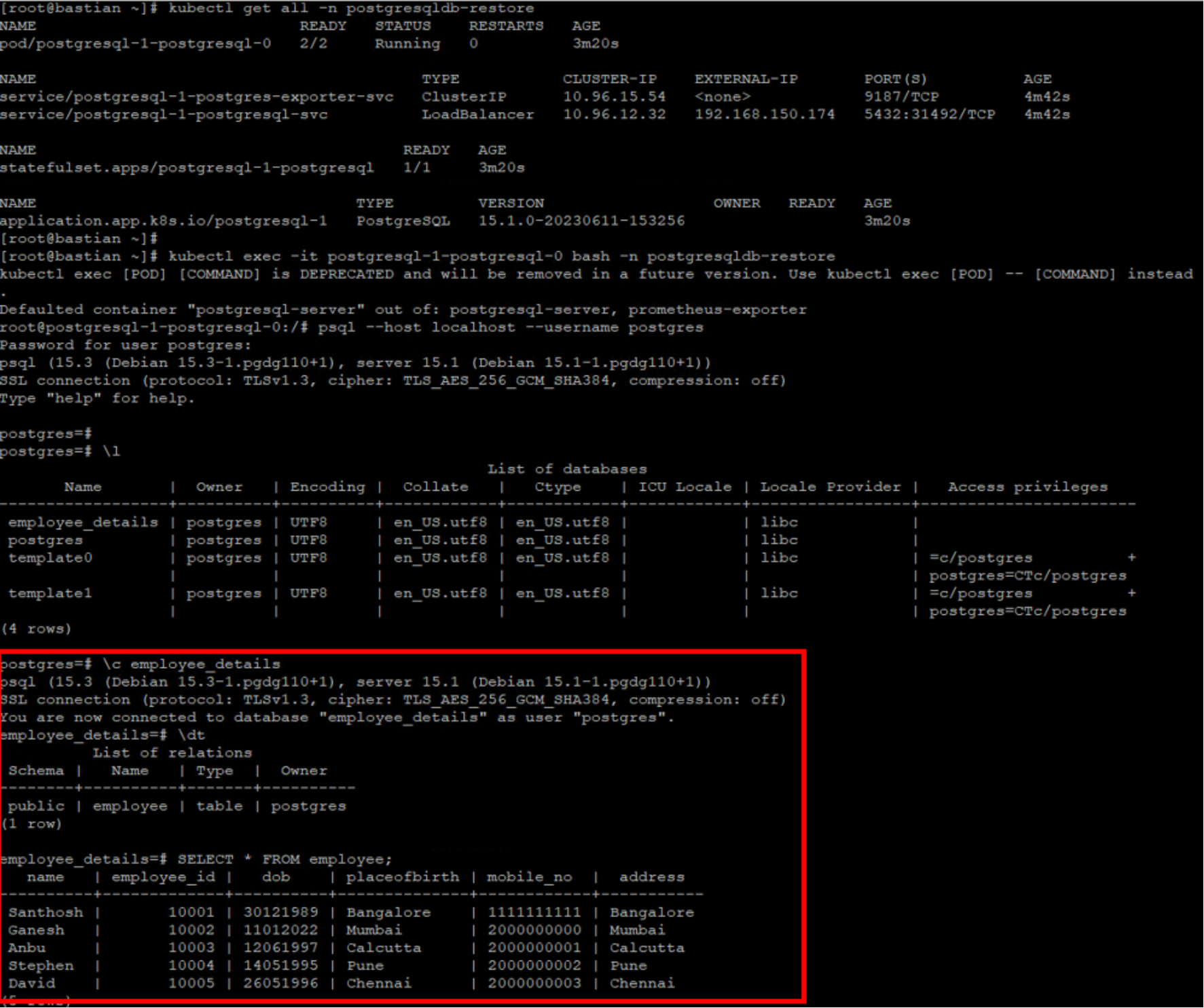
Figure 31. Database and table that is restored on the new namespace
Application-consistent backups
PowerProtect Data Manager also supports agentless, application-consistent backups of database applications that run as Kubernetes pods. It provides a standardized way to quiesce a supported database, back up the data from that database, and then return the database to operation.
Application templates are a bridge between a specific database environment and the Kubernetes backup architecture for the PowerProtect Data Manager. Depending on the differences between database environments, each deployment may require a different configuration file.
Application templates translate the specific configuration details and require interface steps for each database application deployment to the standard PowerProtect Data Manager backup functionality for Kubernetes.
Application templates are typically deployed from customizable YAML files that come with the CLI package. The CLI package exists on the Data Manager host at /usr/local/brs/lib/cndm/misc/ppdmctl.tar.gz and is part of the Data Manager deployment.
You can download the CLI package from the PowerProtect Data Manager UI. Select Settings > Downloads > Kubernetes.
The following figure shows the sample PostgreSQL application template:
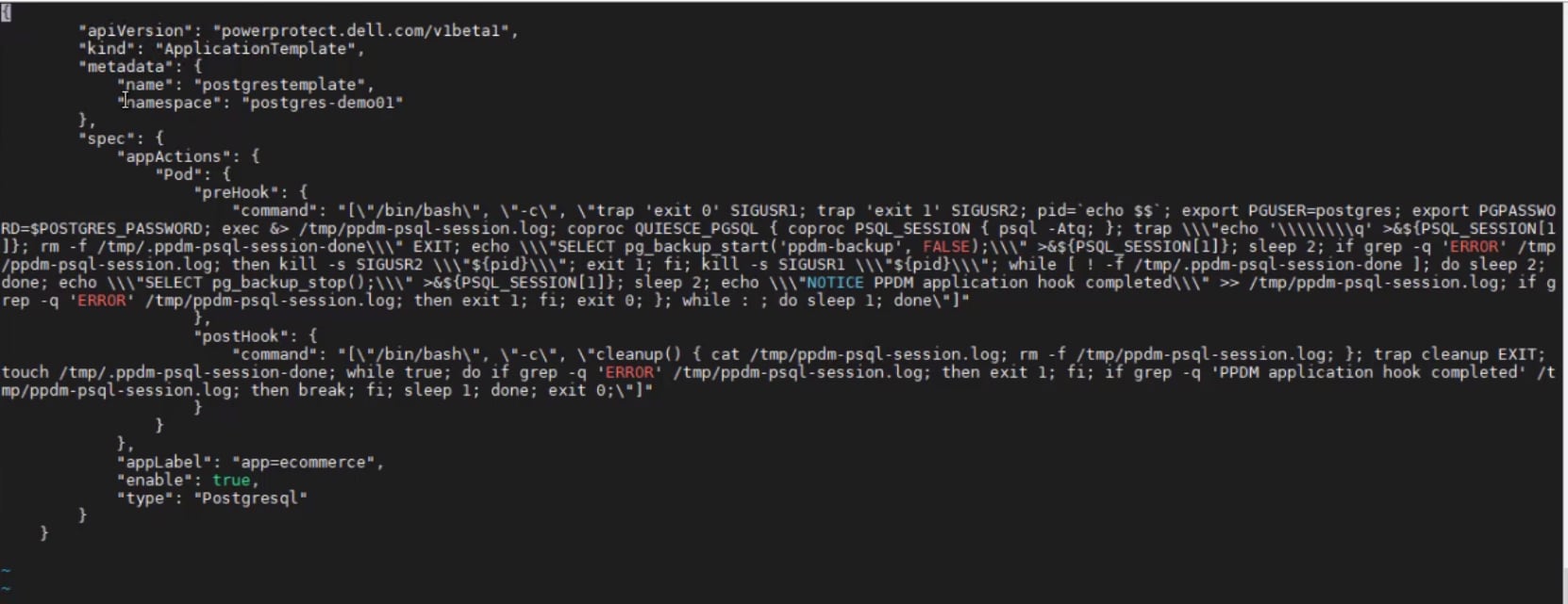
Figure 32. Sample postgresql application template
After you deploy application templates, the agentless nature of the backups means that no special steps are required to perform an application-consistent database backup. We can now go to create a protection policy to perform application consistent backup. The PowerProtect Data Manager infrastructure detects the presence of a deployed template and follows the template instructions when backing up the namespace to which the database application belongs.
Once the backup is completed, the protection copy is made available and from looking in the Consistency column the backup copy is Application Consistent as shown in the following figure.
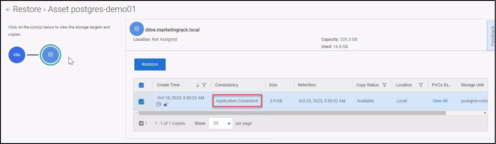
Figure 33. Application consistent backup copy from PowerProtect Data Manager UI
For more information about how to protect Kubernetes workloads with Data Manager, see the PowerProtect Data Manager Kubernetes User Guide.