Implementing Dell PowerFlex with VMware Tanzu
Introduction
Executive summary
Document purpose
Audience
Terminology
Product overview
PowerFlex family overview
PowerFlex software-defined infrastructure enables broad consolidation across the data center, encompassing almost any type of workload and architecture. The software-defined architecture offers automation and programmability of the complete infrastructure and provides scalability, performance, and resiliency to enable effortless adherence to stringent workload SLAs.
The PowerFlex family provides a foundation that combines compute and high-performance storage resources in a managed unified fabric. PowerFlex comes in flexible deployment options (rack, appliance, or custom nodes and in the public cloud) that enables independent (two-layer), HCI (single-layer), or mixed architectures. PowerFlex is ideal for high-performance applications and databases, building an agile private-hybrid cloud, or consolidating resources in heterogeneous environments.
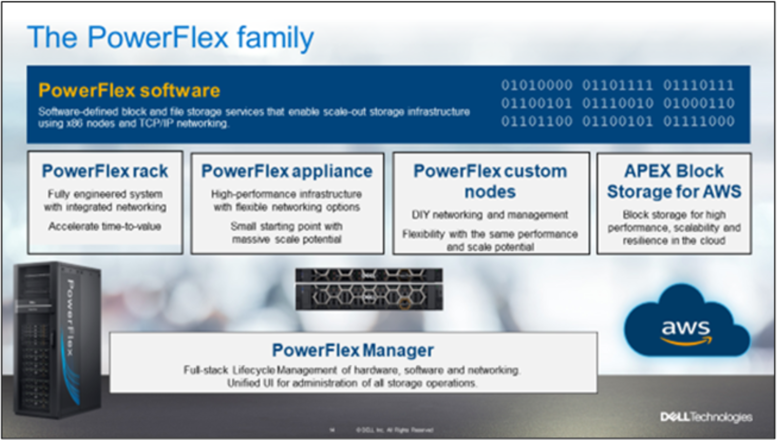
Figure 1. PowerFlex family
PowerFlex software components
Software is the key differentiation in the PowerFlex offering. PowerFlex software components not only provide software-defined storage services, but also help simplify infrastructure management and orchestration. This software enables comprehensive IT Operational Management (ITOM) and Life Cycle Management (LCM). These capabilities span compute and storage infrastructure, from BIOS and Firmware to nodes, software, and networking.
PowerFlex
PowerFlex is the software foundation of PowerFlex software-defined infrastructure. It is a scale-out block and file storage service that is designed to deliver flexibility, elasticity, and simplicity with predictable high performance and resiliency at scale.
PowerFlex Manager
PowerFlex Manager is the software component in the PowerFlex family that enables ITOM automation and LCM capabilities for PowerFlex systems. Starting with PowerFlex 4.0, the unified PowerFlex Manager brings together three separate components from previous releases: PowerFlex Manager, the core PowerFlex UI, and the PowerFlex gateway. The new PowerFlex UI runs in Kubernetes and embraces a modern development framework.
PowerFlex file services
PowerFlex File Controllers, also known as File Nodes, are physical nodes that enable PowerFlex software defined File Services. They host the NAS Servers, which in turn host tenant namespaces and file systems, mapping PowerFlex volumes to the file systems presented by the NAS Servers. All major protocols are supported, such as NFS, SMB-CIFS, FTP, and NDMP. PowerFlex file service is supported from PowerFlex 4.0.
PowerFlex CSI and CSM
An important component outside of PowerFlex that enables a flexible consumption model for Kubernetes is the PowerFlex CSI driver. It was developed as a part of the Dell Kubernetes strategy. After the CSI driver for PowerFlex is loaded into Kubernetes, it can be used to provision persistent volumes from the underlying PowerFlex storage resource. If the Kubernetes deployment is running low on PowerFlex storage resources, you can add PowerFlex storage nodes to increase the system capacity and performance.
The CSI driver connects the PowerFlex system and Kubernetes deployments. It is a storage broker agent which dynamically provisions volumes from PowerFlex through the PowerFlex API gateway to the Kubernetes cluster. Once the volume is available on PowerFlex, it is immediately mapped to the requesting pod. If a pod is destroyed or rescheduled, the CSI plug-in ensures that the volumes are remapped upon rescheduling of that pod.
Customers running Kubernetes clusters on PowerFlex use the Dell Container Storage Modules (CSM), which extend the CSI driver capabilities. These modules:
- Provide enterprise storage capabilities to Kubernetes for cloud-native stateful applications.
- Reduce management complexity, so that developers can independently use enterprise storage with ease and automate daily operations.
- Extend storage functionality and capabilities beyond using the CSI driver alone.
These modules include snapshot, observability, authorization, application mobility, and resiliency.
PowerFlex supports multiple operating systems and different deployment options for on-premises and public cloud deployment models (available in AWS). PowerFlex is validated with the leading Kubernetes distributions as shown in Figure 2.
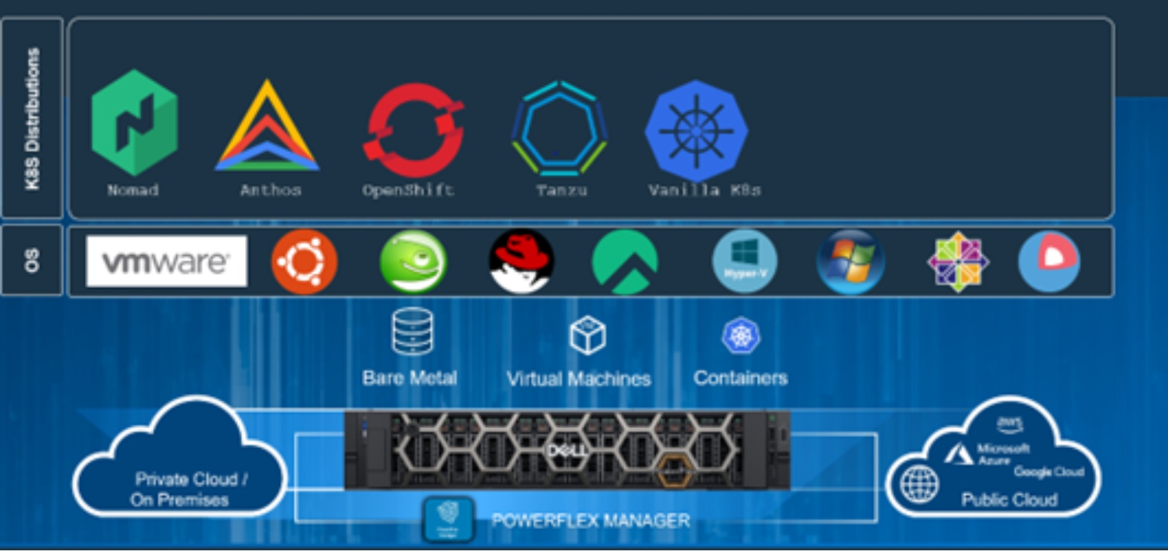
PowerFlex deployment architectures
PowerFlex software-defined infrastructure excels in deployment flexibility. PowerFlex can be deployed in a two-layer (independent compute and storage layers), single-layer (Hyperconverged Infrastructure, or HCI), or a mixture of the two architectures (Mixed).
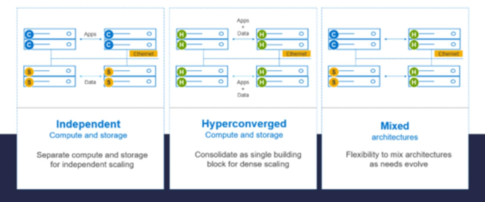
Figure 3. PowerFlex architectures
Independent architecture
In an independent architecture or two-layer architecture, some nodes provide storage capacity for data in applications. Other separate and independent nodes provide compute resources for applications and workloads. Compute and storage resources can be scaled independently by adding nodes to the cluster while it remains active. This separation of compute and storage resources helps to minimize software licensing costs in certain situations. This architecture can be ideal for high-performance databases and application workloads.
Hyperconverged architecture
In an HCI architecture, each node in the cluster contributes storage and compute resources simultaneously to the applications and workloads. This architecture allows you to scale your infrastructure uniformly with building blocks that add both storage and compute resources. This architecture is appropriate for data center and workload consolidation.
Mixed architecture
A mixed architecture has a combination of both the HCI and Independent architectures. As shown in Figure 3 above, there would be some storage only nodes, compute only nodes, and hyperconverged nodes as part of the same PowerFlex cluster. This architecture is desirable when working with an existing compute infrastructure and adding high-performance software-defined infrastructure. This architecture can also be a starting point for a two-layer deployment design as external workloads are migrated to PowerFlex.
PowerFlex consumption options
Tanzu
Environment and system requirements
Introduction
Prerequisites
Solution architecture
This section describes the different types of topologies that make up the solution.
Network topology
At the physical layer, two supported Top of Rack (TOR) switches are used for redundancy and load-balancing purposes. There are four connections from each Dell host, two to TOR A and two to TOR B. Three of the connections are used, one for PowerFlex management and two for PowerFlex data. The data connections are split between the switches.
The following table shows the different networks that are configured for this solution.
Table 3. Network VLANs
|
Network type |
VLAN ID |
|
PowerFlex Management |
1109 |
|
PowerFlex Data 1 |
20 |
|
PowerFlex Data 2 |
30 |
Figure 4 shows a VMware network topology for the Tanzu implementation using the components in this solution: NSX Advanced Load Balancer and vSphere Networking, or more specifically the use of a vSphere Distributed Switch (VDS). The bottom half of the image references the Supervisor Cluster upon which the Tanzu Kubernetes clusters are built. The TKG boxes are the Kubernetes (Guest) cluster.
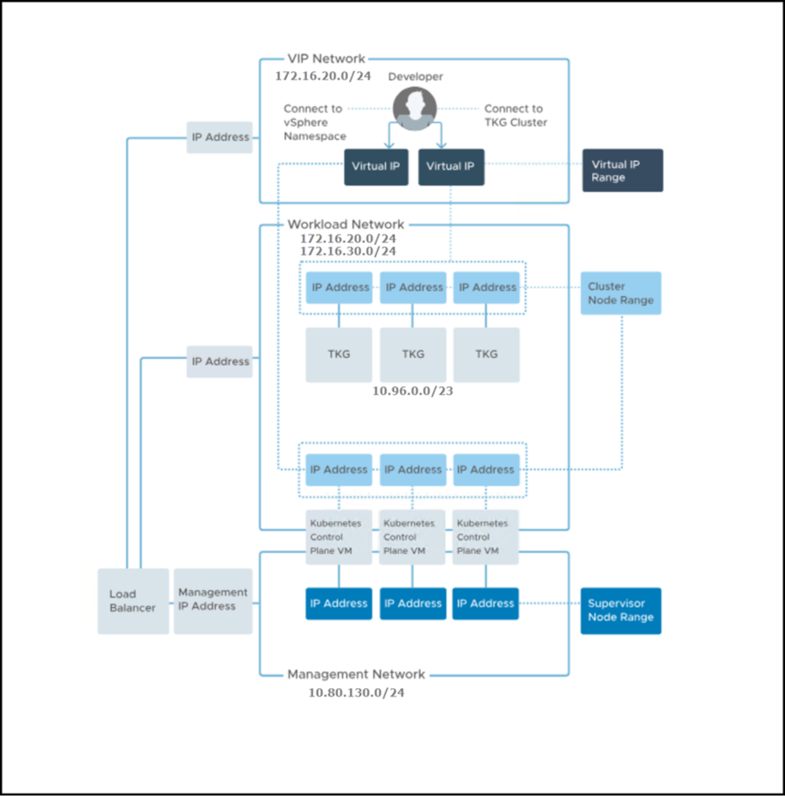
Figure 4. VMware-provided network topology for Tanzu with NSX Advanced Load Balancer
PowerFlex topology
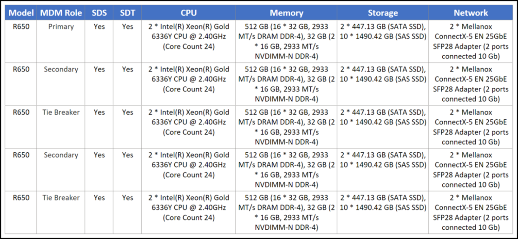
The PowerFlex system consists of five nodes with the characteristics that are covered in Table 4. There is no SDC installed on any of the PowerFlex nodes as the volumes are only mapped to the ESXi hosts.
Table 4. PowerFlex node configurations
VMware topology
The VMware environment is a single vCenter with two clusters, Management and Workload, each with three ESXi hosts with the same configuration as the PowerFlex nodes. A visual depiction is in Figure 5.
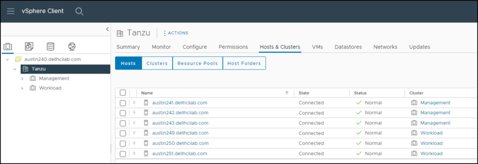
Figure 5. VMware vCenter
Protocol topology
Figure 6 and Figure 7 are logical depictions of the host connectivity between the VMware infrastructure and the PowerFlex. This solution uses both NVMe/TCP and SCSI (SDC) protocols to provision storage to the VMware environment. This concept holds true for both the Tanzu installation and the persistent storage that is created for Tanzu Kubernetes Clusters.
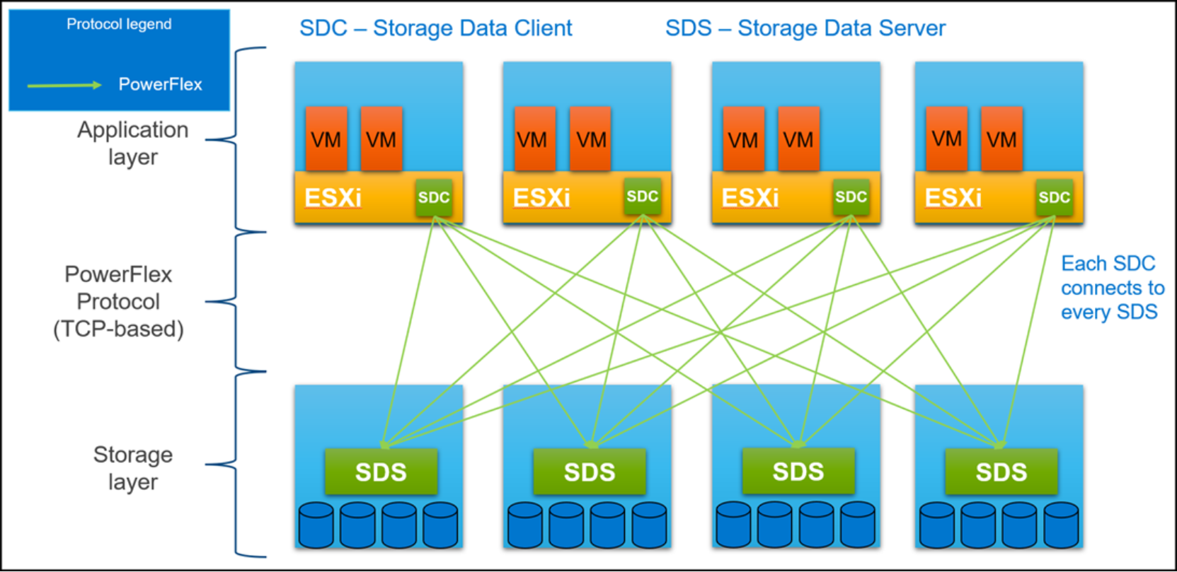
Figure 6. PowerFlex protocol host connectivity
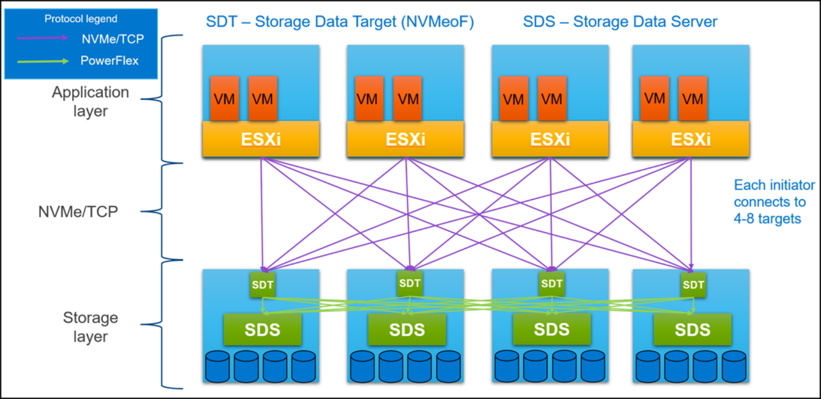
Figure 7. NVMe/TPC protocol host connectivity
Host connectivity
Introduction
Adding SDC to VMware
PowerFlex delivers the SDC as a vSphere Installation Bundle (VIB) that must be installed on ESXi. Although it is possible to do so manually, Dell offers the Virtual Storage Integrator (VSI) which automates the process.
VSI
The following procedures use VSI to add the storage systems.
Add the PowerFlex storage systems
- Register the PowerFlex environment in VSI. In vCenter, go to Dell VSI in the main menu as shown in Figure 8.
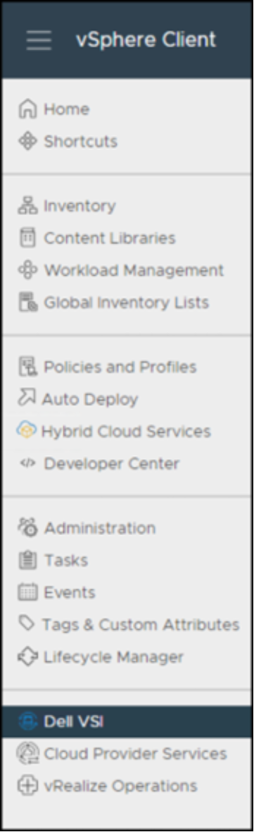
Figure 8. Dell VSI
- Select the Storage Systems option as shown in Figure 9, and then click the plus (+) button.
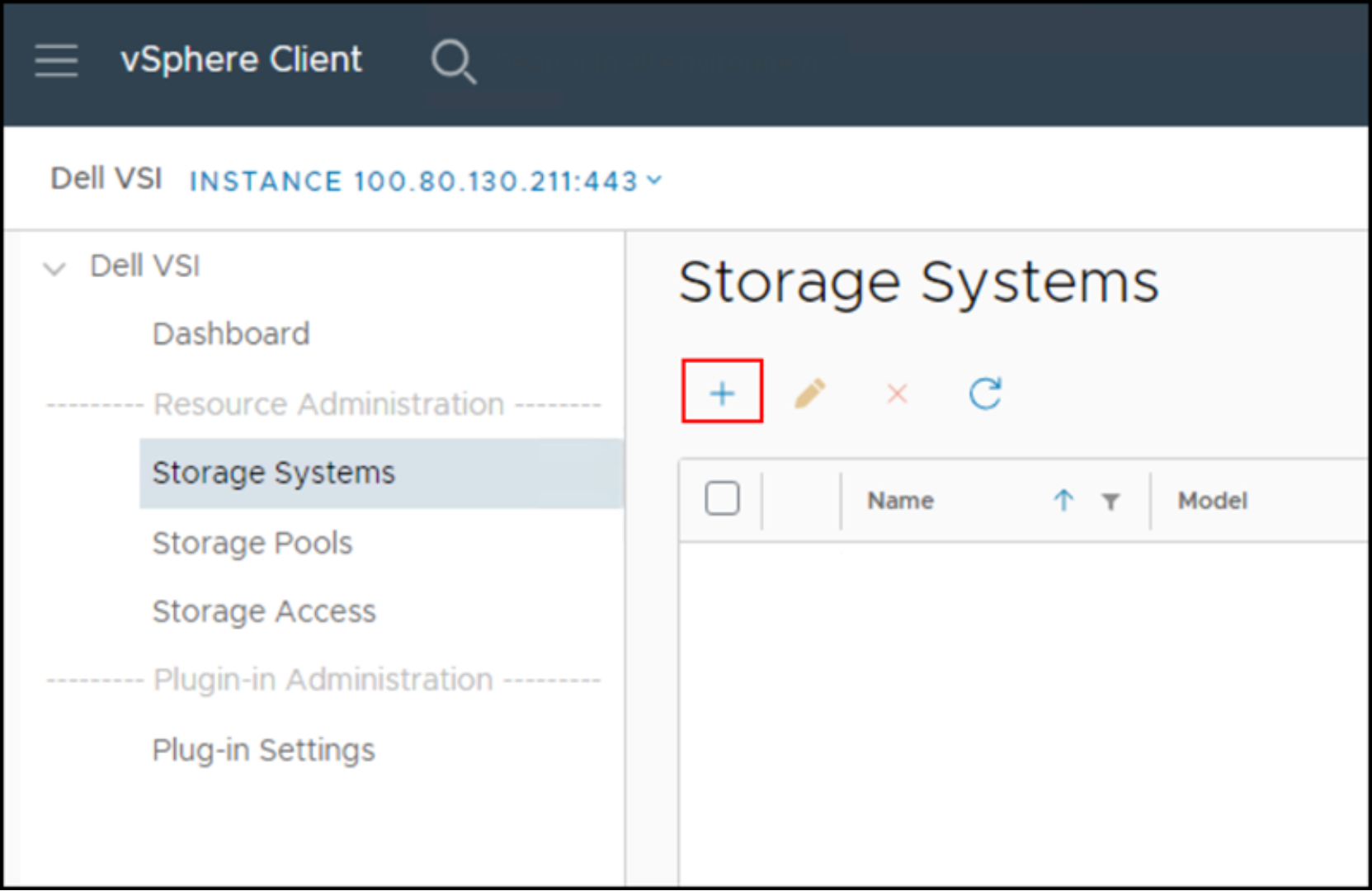
Figure 9. Dell VSI: Add PowerFlex storage system
- Choose PowerFlex from the drop-down storage systems as shown in Figure 10.
- Enter the appropriate information.
- Select NEXT.
Note: The PowerFlex Gateway for 4.0.x version is the same as the UI IP.
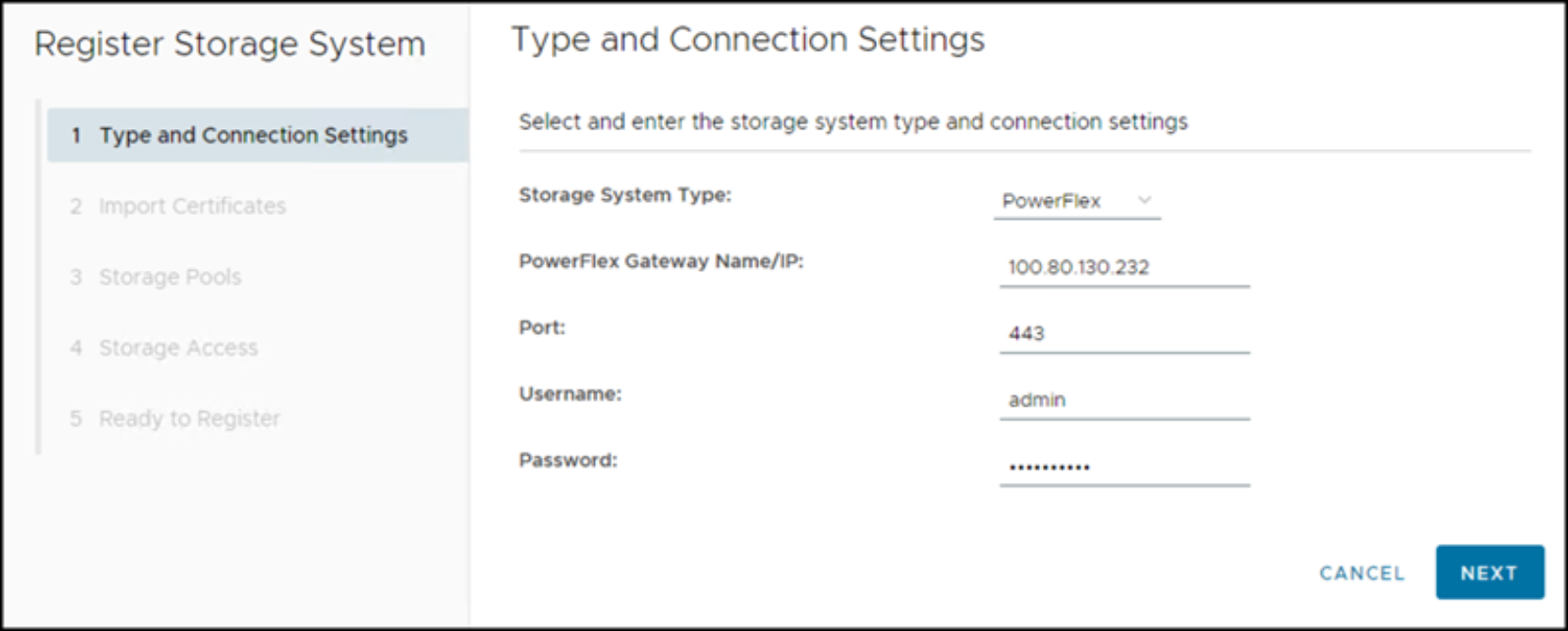
Figure 10. DELL VSI: Add PowerFlex storage system – Step 1
- Choose whether to import certificates.
- Select NEXT.
- VSI then displays all available storage pools on the PowerFlex that are available to select.
Note: Some customers may have separate pools for Tanzu work. In this example, there is only one pool.
- Select NEXT.
- Choose whether any user other than an administrator can use some VSI functionality.
- Select NEXT.
- Review your selections.
- Select FINISH.
- The system is now available in the Storage Systems. Select it to view the details as shown in Figure 11.
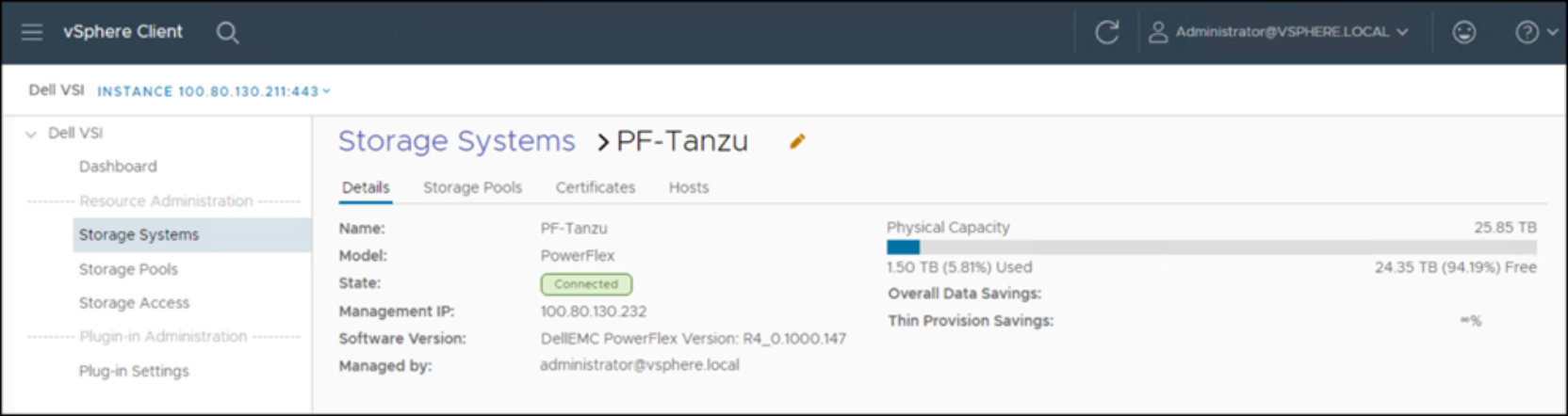
Figure 11. Dell VSI: Add PowerFlex storage system – PF-Tanzu
Add the SDC
- After the PowerFlex is added to VSI, select the Hosts tab. Here, in Figure 12, VSI recognizes that three hosts are available for an SDC installation.
- Click the plus sign to begin the SDC installation process.
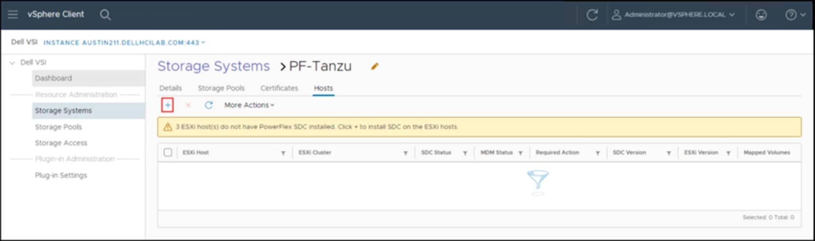
Figure 12. Dell VSI: Add SDC – Step 1
- To install the SDC using VSI, place the .zip file (for example, sdc-4.0.0.1211-esx7.x.zip) in the same location on every ESXi host.
Note: This procedure can be done individually on each host, or by using a shared datastore. The environment may not include other arrays to create a shared VMFS. In these cases, Dell Technologies advises creating a Windows share which can then be mounted as an NFS datastore on each ESXi host. Doing so avoids keeping a copy of the .zip file on each host and guarantees that every host uses the same file.
- Click INSTALL.
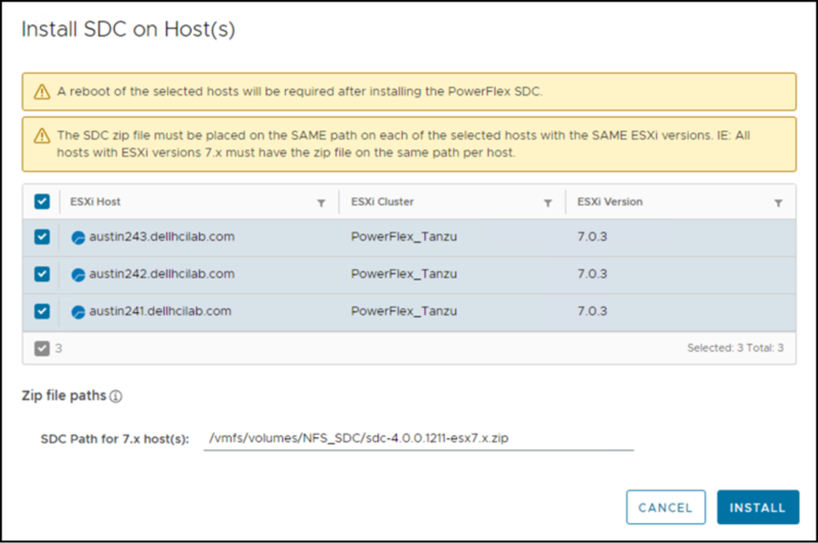
Figure 13. Dell VSI: Add SDC – Step 2
- When the installation is complete, VSI displays a message, as shown in Figure 14, stating that the hosts must be rebooted.
Note: VSI does not automatically reboot the hosts.
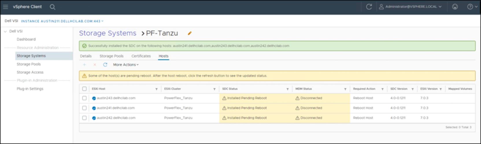
Figure 14. Dell VSI: Add SDC – Step 3
- Reboot the hosts.
- After the host comes back up, return to the Hosts screen to see the updated status, as shown in Figure 15. VSI updates the parameters on the ESXi host in the scini module which connect the host to the registered PowerFlex (MDM) environment.
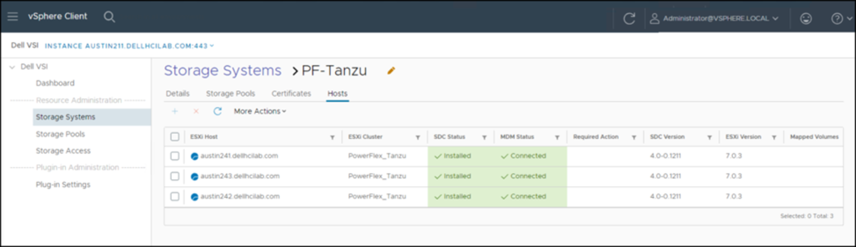
Figure 15. Dell VSI: Add SDC – Complete
Rename the hosts
When the SDC install completes, Dell Technologies recommends renaming the host in the PowerFlex UI for ease of use. Doing so is important if using both SDC and TCP on the same host.
Note: VSI is only a green-field option since it cannot resolve issues that are related to improper installations. If any of the ESXi hosts in the cluster have unresolved SDC components on them already, VSI displays the following error.

Figure 16. Error constructing hostname
Adding NVME/TCP to VMware
Introduction
While VSI can install SDC for users, it cannot configure NVMe/TCP on the ESXi host. It is a manual process that users must complete on each ESXi host that require access to storage through this protocol. The following procedures walk through this configuration on one of the ESXi hosts in the Tanzu cluster.
Add the NVME/TCP adapter
As covered in Protocol topology, NVMe/TCP does not require a separate installation on the ESXi host. Rather, the NVMe/TCP software adapter attaches to the NVMe target (SDT process) on one or more PowerFlex nodes. In the PowerFlex system used in this guide, the SDT process uses the same Ips as SDC. Therefore, the data networks of VLAN 50 and 100 are used.
- Before adding a NVMe/TCP adapter, determine the physical adapters for each VLAN.
- Select the NVMe over TCP service on the VMkernel as shown in Figure 17.
- Select OK.
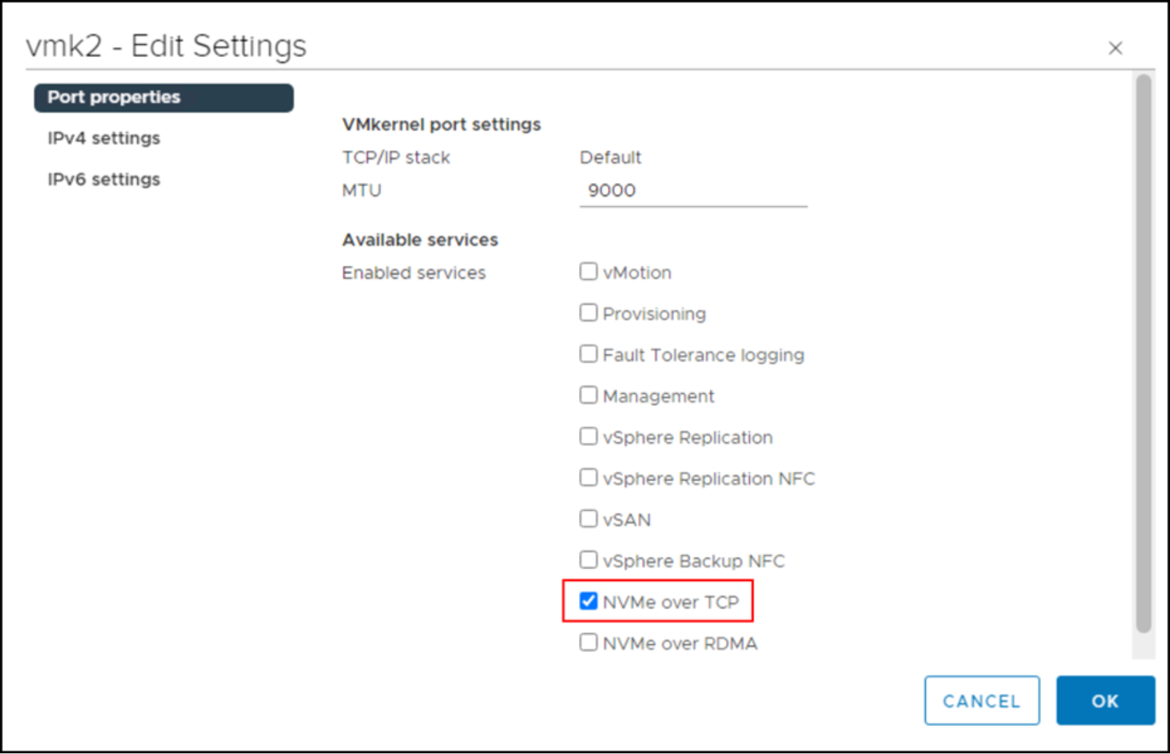
Figure 17. Enable the NVMe/TCP service on the VMkernel
- With the service enabled, go to Host -> Configure -> Storage Adapters -> ADD SOFTWARE ADAPTER.
- Use the drop-down to pick the correct physical NIC for the selected VLAN.
Add the NVMe host to PowerFlex
Before adding the controllers to the adapter, you must create the NVMe host on the PowerFlex by obtaining the host NQN from vSphere.
- Go to Host -> Configure -> Storage Adapters.
- Select the newly added storage adapter as shown in Figure 18.
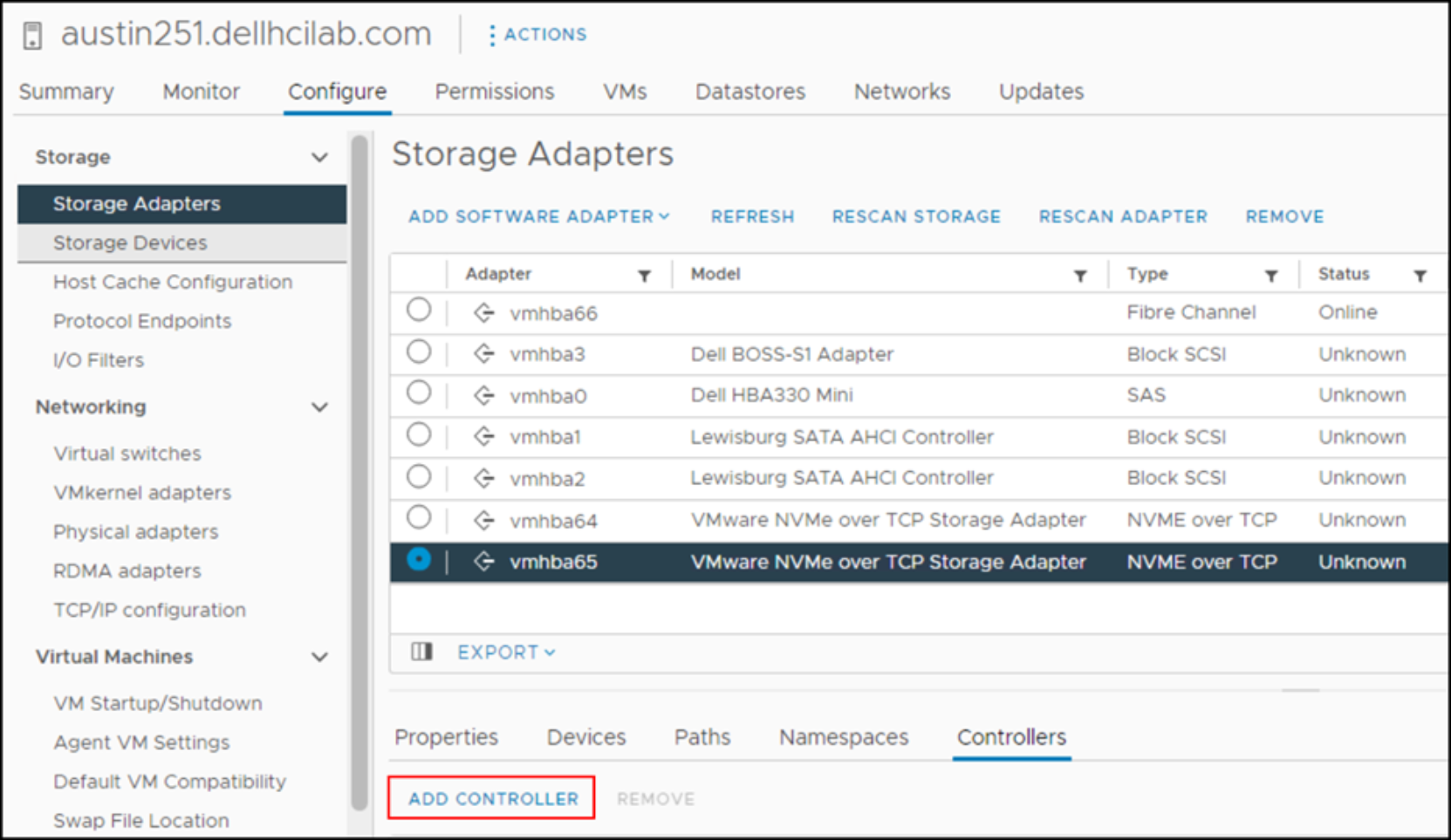
Figure 18. Select the storage adapter
- Select the Controllers tab.
- Select ADD CONTROLLER.
- In the screen that follows, select the COPY button next to the Host NQN as shown in Figure 19.
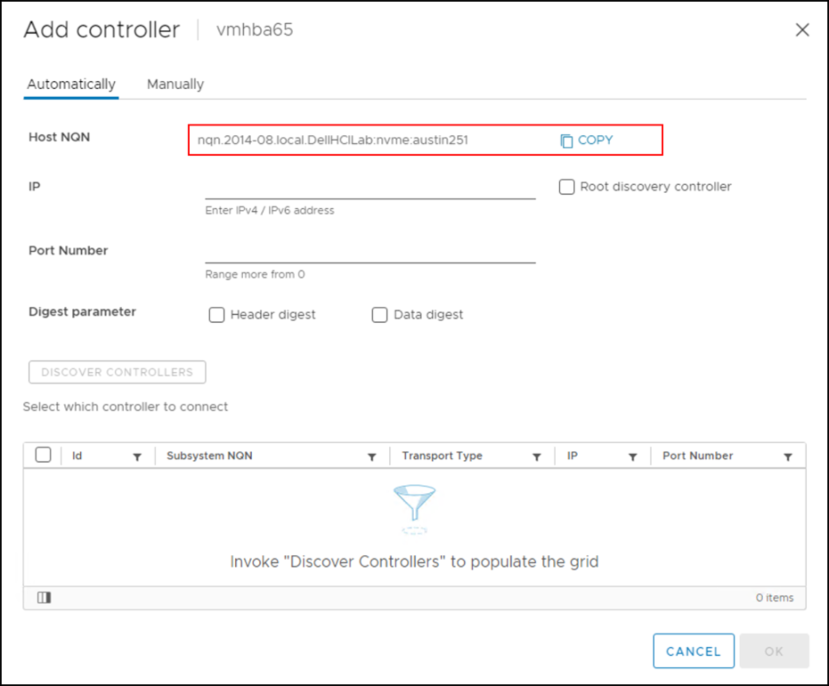
Figure 19. Copy host NQN
- Open the PowerFlex management UI and go to the Block -> Hosts menu.
- Select + Add Host.
- Paste the copied host NQN into the Host NQN field and provide a Host Name.
- Leave the other fields as default, as shown in Figure 20.
Note: Since both SDC and NVMe/TCP are being used, the suffix “_nvme” is added to the hostname.
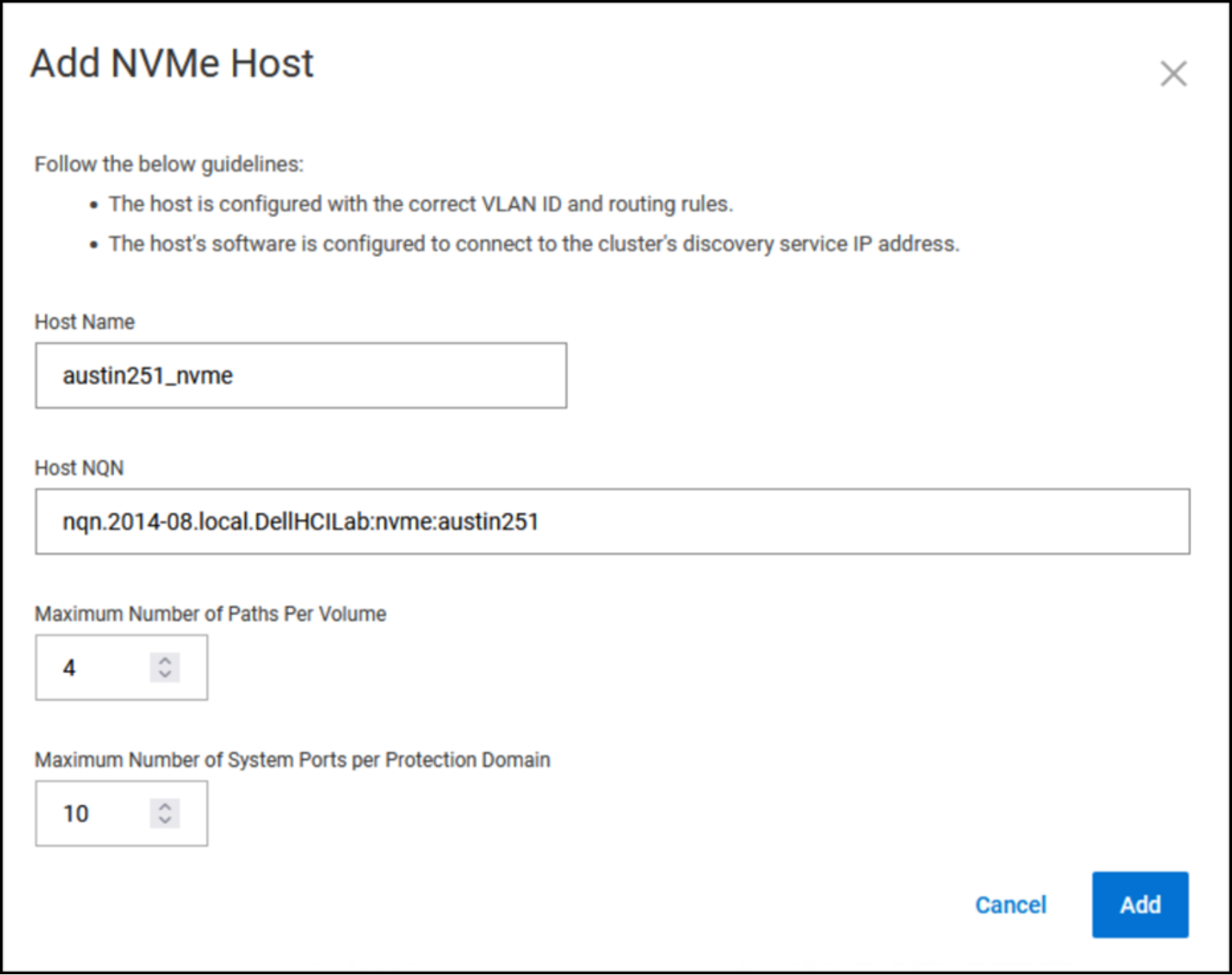
Figure 20. Add NVMe host
Add the NVMe controller
The SDT IP addresses are required in order to add the controller. These addresses can be obtained from the storage admin or by users with access to the PowerFlex UI.
- While still in the PowerFlex UI, go to Block -> NVMe Targets.
- Select one of the SDTs listed, and on the right side find the IP addresses. These addresses are the controller IP addresses
- Return to vSphere.
- Go to the ADD CONTROLLER screen as shown in Figure 19.
- Enter the copied IP address into the IP field.
- Enter 8009 into the Port Number field (4420 also works).
- Select DISCOVER CONTROLLERS. The NVMe target is displayed.
- Select the NVMe target, and then click OK, as shown in Figure 21.
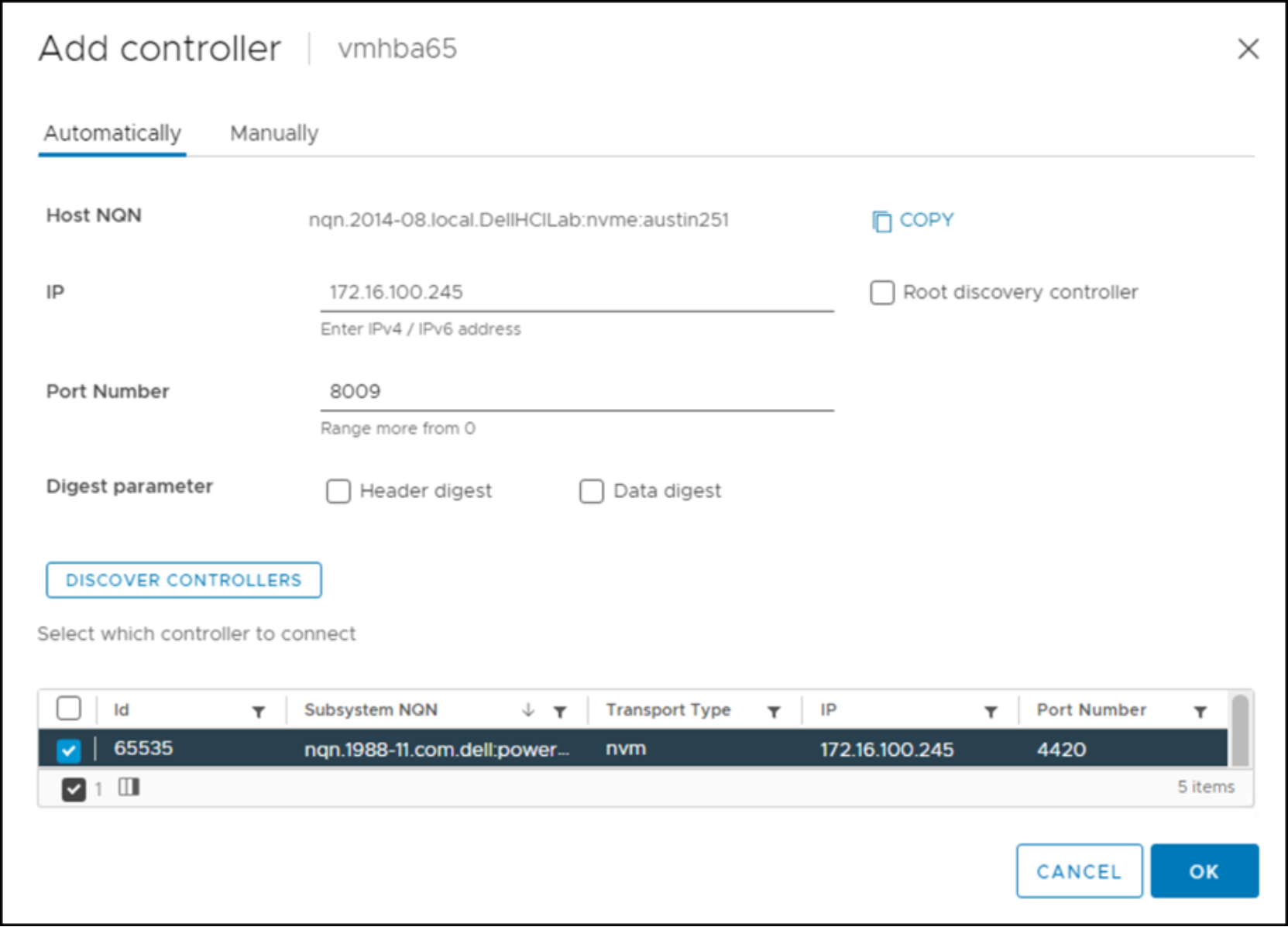
Figure 21. Add controller
- Repeat this process for each of the NVMe target Ips in VLAN 100.
- Add a second NVMe/TCP adapter for VLAN 50.
- You can now map devices to the ESXi host.
Provision storage
Introduction
With connectivity to the ESXi hosts established, you can create and map volumes for the VMware datastores. For both SDC and NVMe/TCP this task can be accomplished directly in the PowerFlex UI. However, VSI enables users to provision datastores from the vCenter for SDC mappings. VSI does not support NVMe/TCP (or NFS). An example of each follows, beginning with the PowerFlex UI.
NVMe/TCP datastores
- Log in to the PowerFlex UI.
- Go to Block -> Volumes.
- Select + Create Volume as shown in Figure 22.
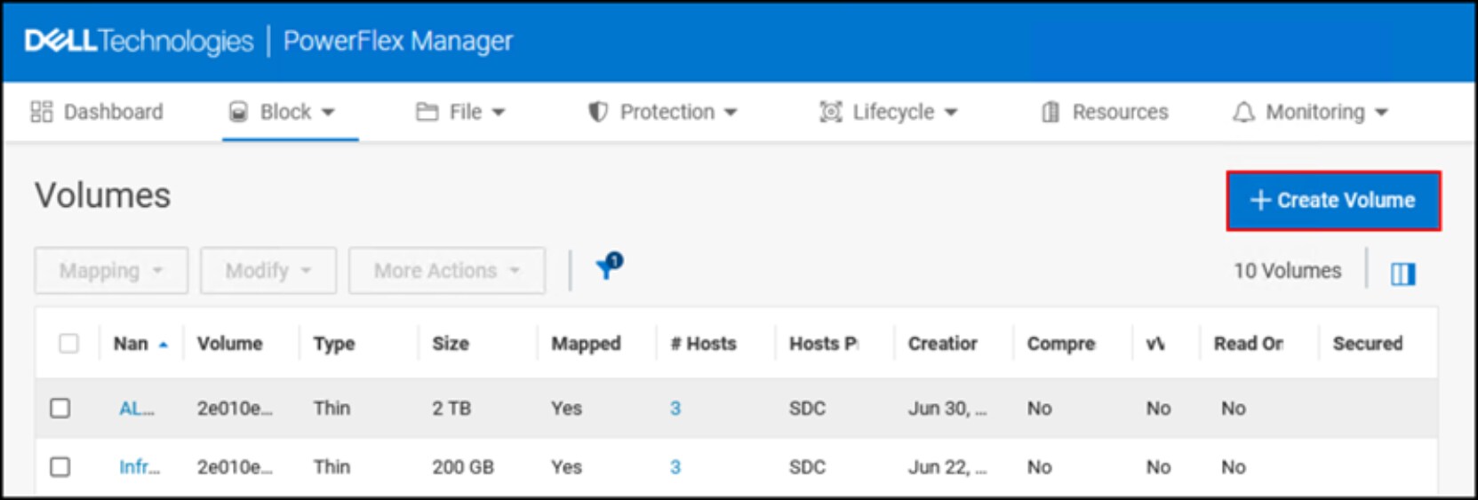
Figure 22. NVMe/TCP datastores – Step 2
- In the Create Volume screen, the Number of volumes defaults to 1.
- Enter a Volume name.
- Leave Provisioning as the default Thin.
- Select a size. This example uses 2 TB.
- Select the Storage Pool.
- Click Create to complete the wizard.
- After volume creation, use the check box to select the new volume.
- From the Mapping menu, select Map as shown in Figure 23.
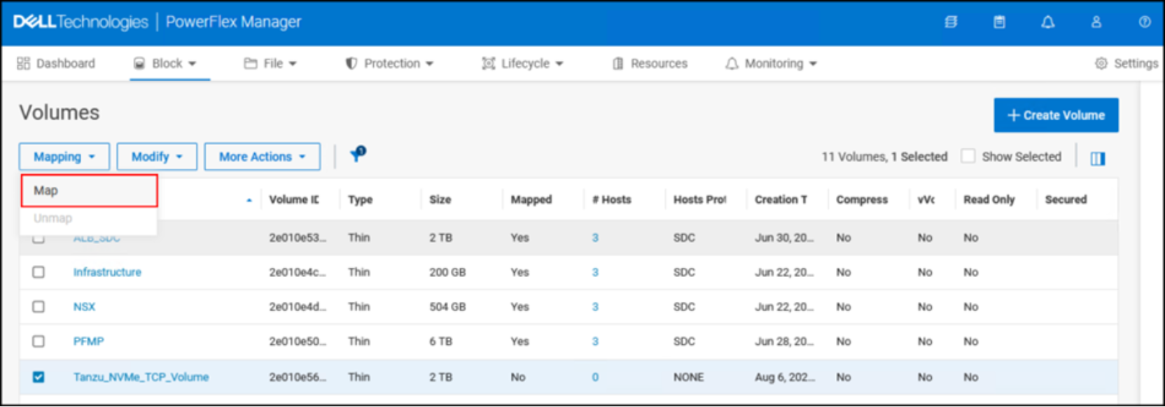
Figure 23. NVMe/TCP datastores – Step 4
- Use the radio button at the top to choose the NVMe protocol.
- Using the check boxes, select the NVMe hosts where to map the volume.
- Click Map.
Note: The volume will be available to the hosts for datastore creation after mapping.
- Go to any of the ESXi hosts.
- Select Configure -> Storage -> Storage Adapters.
- Select one of the NVMe/TCP adapters to view the newly presented device.
- Log in to vCenter.
- From the data center level, go to Datastores, then go to ACTIONS -> Storage -> New Datastore.
- Use the radio button to select the newly presented TCP volume.
- Provide a Name.
- Select NEXT to complete the wizard.
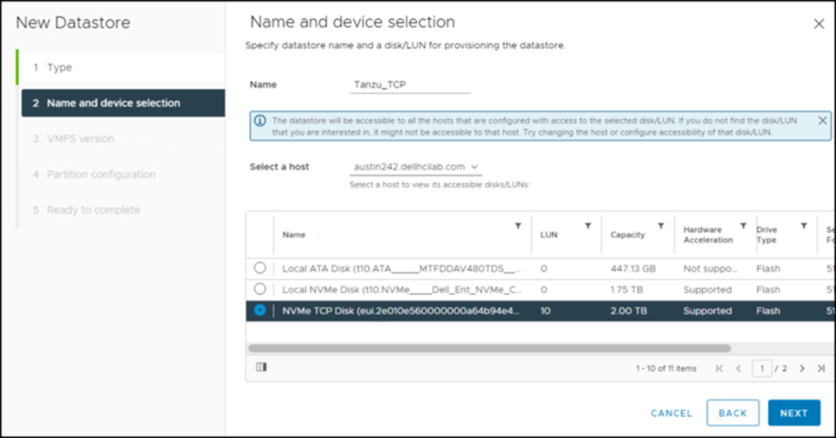
Figure 24. NVMe/TCP datastores – Step 8
The remaining steps are the same for TCP as any other device. The result is shown in Figure 25.
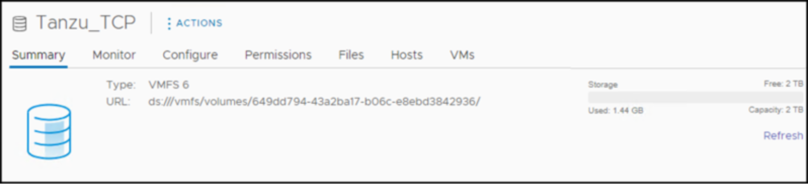
Figure 25. NVMe/TCP datastores – Complete
SDC datastores
For datastores with backing volumes that are mapped to SDC:
- In the vSphere UI, right-click at the data center, cluster, or host level.
- Select Dell VSI -> Create Datastore. This example is shown at the data center level in Figure 26.
Note: This task starts the Create Datastore wizard, which is a combination of VSI and VMware functionalities.
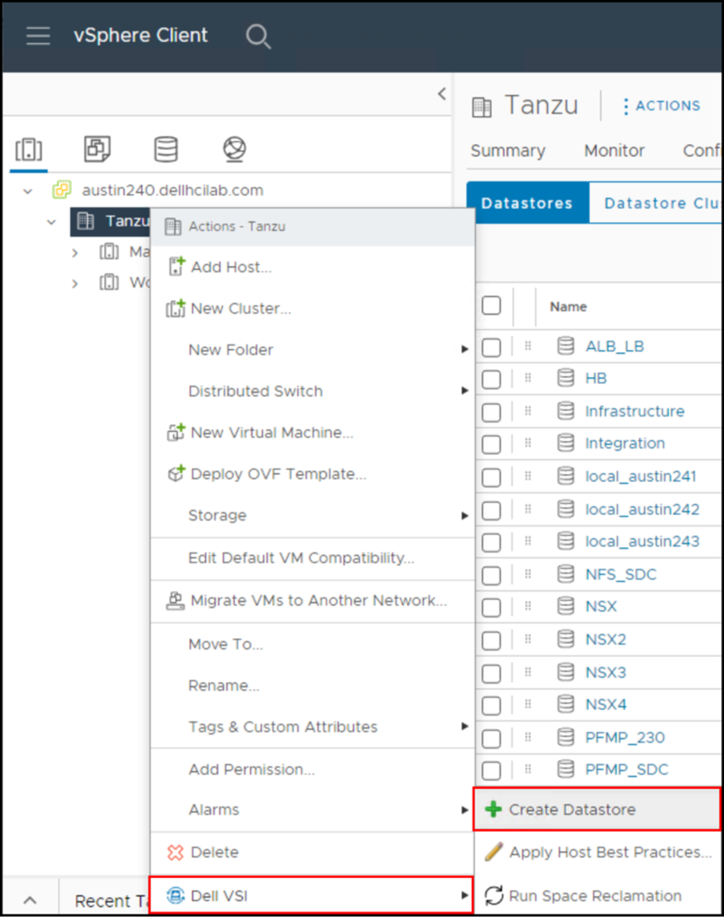
Figure 26. SDC datastores – Start VSI wizard
- Select VMFS for the type of datastore to create, as shown in Figure 27.
Note: VMFS is the only type that is supported for PowerFlex on VSI as of the publication of this guide.
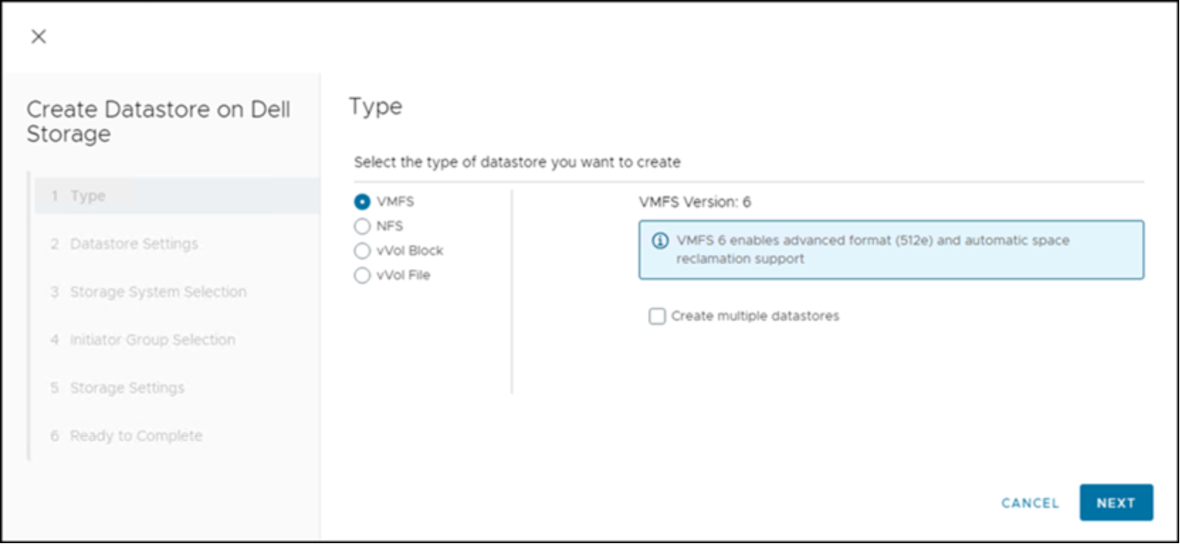
Figure 27. SDC datastores – Step 1
- Click NEXT to continue.
- Enter a Name for the datastore.
- Click NEXT.
VSI displays the available storage systems that the user registered in VSI. These systems could include PowerFlex and non-PowerFlex storage. In this example, there is a single PowerFlex storage system, named PF-Tanzu.
- Select a storage system as shown in Figure 28.
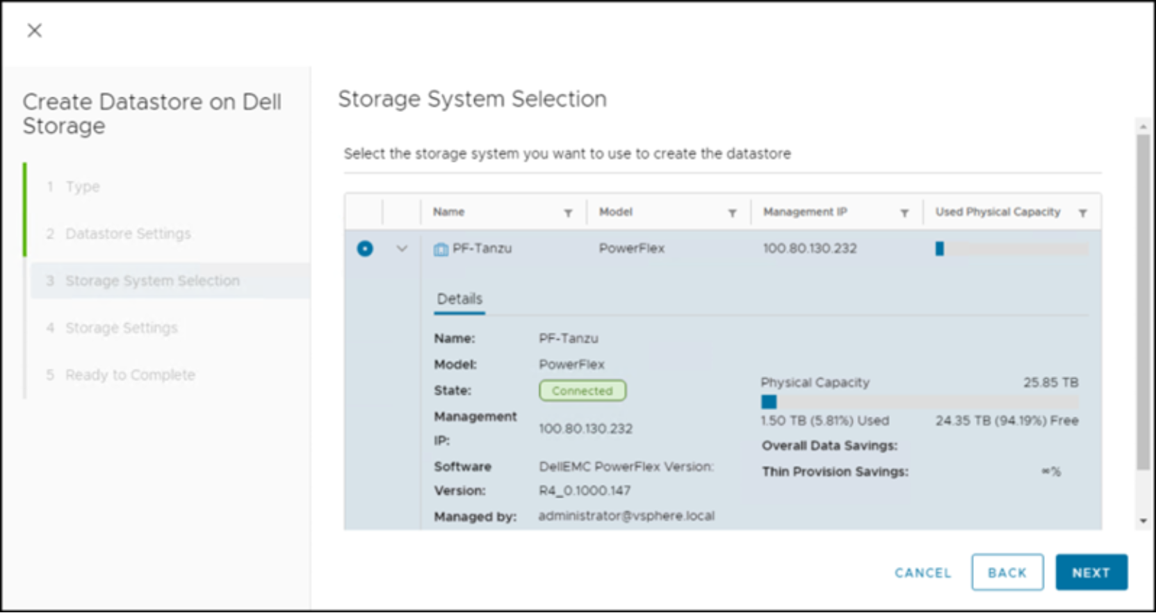
Figure 28. SDC datastores – Step 3
- Click NEXT.
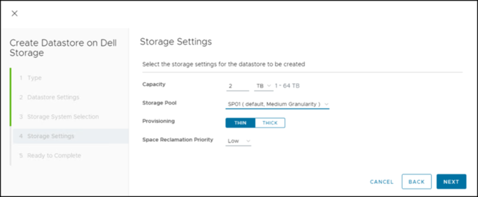
Figure 29. SDC datastores – Step 4
- Under Storage Settings, enter a capacity for the datastore.
- Use the drop-down box to pick the storage pool.
Note: Only one pool is available in this example.
- Click NEXT.
- Review the input information.
- Click FINISH. VSI then performs the following:
- Provisions the volume
- Maps it to all SDC hosts that are part of either the data center, cluster, or ESXi host, depending on what was selected at the start
- Creates a datastore on it
- Find the newly created datastore.
- Go to Configure -> Dell VSI -> Configure Storage.
The Storage Settings tab defaults with information about the volume, as shown in Figure 30.
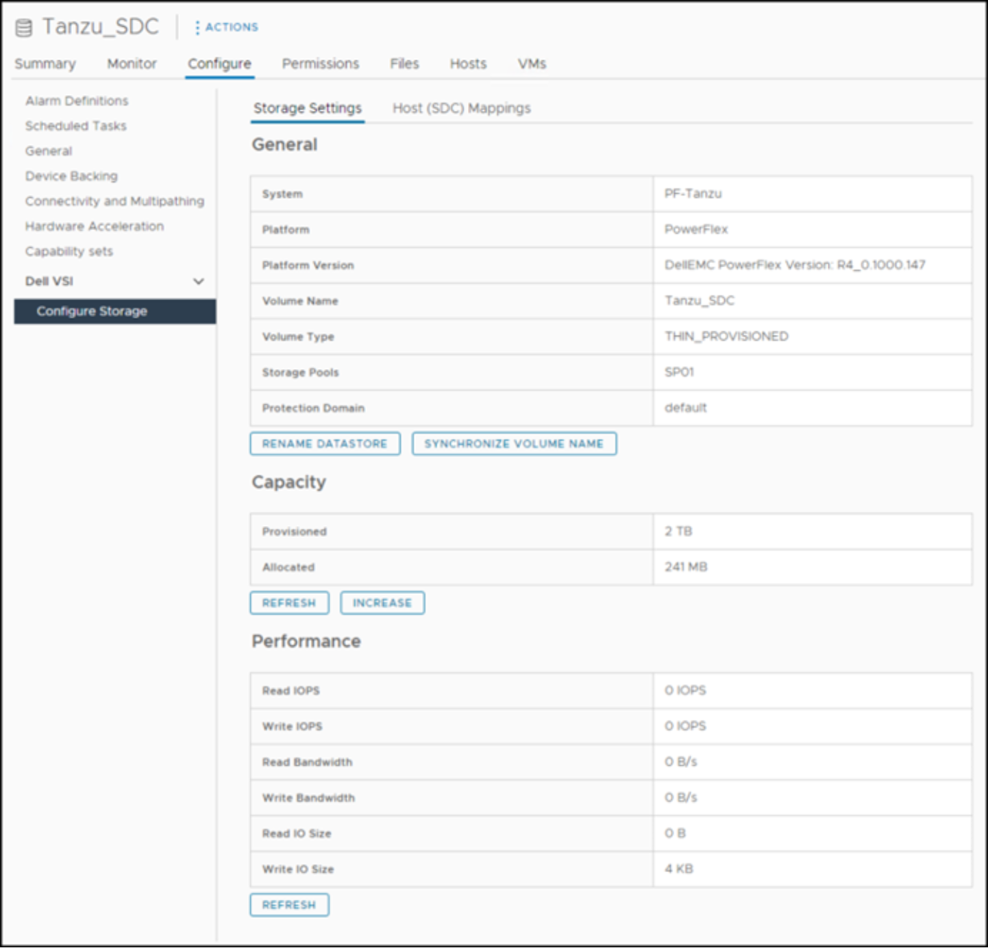
Figure 30. Tanzu_SDC datastore in VSI – Storage Settings
- To see the SDC hosts to which VSI mapped the volume, select the Host (SDC) Mappings tab as shown in Figure 31.
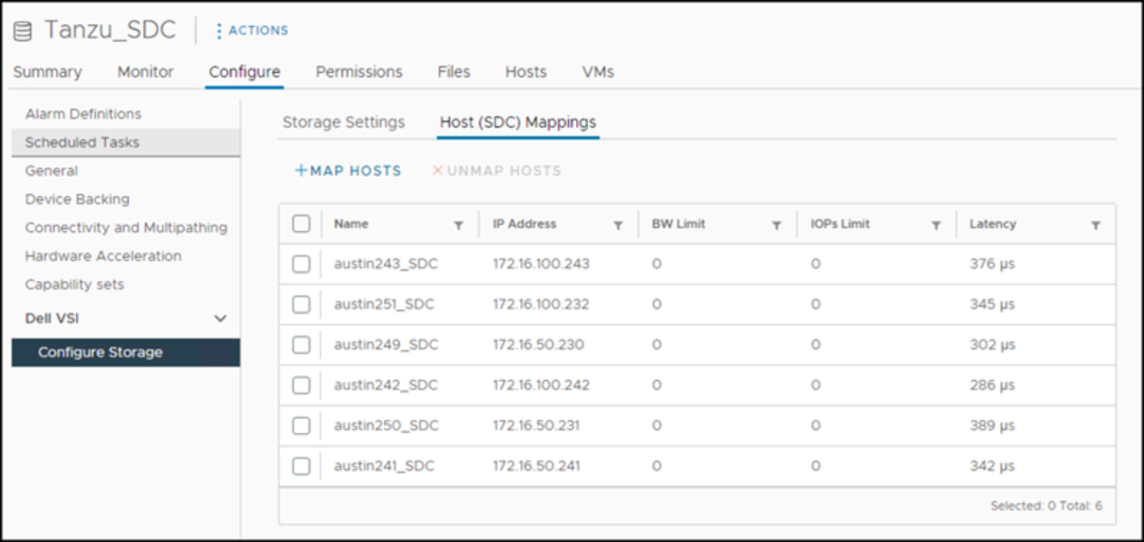
Configuring VMware infrastructure
Introduction
VMware storage policies
Introduction
The following sections include the creation of two storage policies for the Tanzu environment. Both category and tag creation are covered as precursors to the policy creation. A category is required before the user creates tags because tags are assigned a category.
Note: A category can be shared among multiple tags.
Category
- In vSphere, click the hamburger menu (
 ) on the left.
- Select Tags & Custom Attributes.
- Select NEW under the Tags-CATEGORIES option as shown in Figure 32.
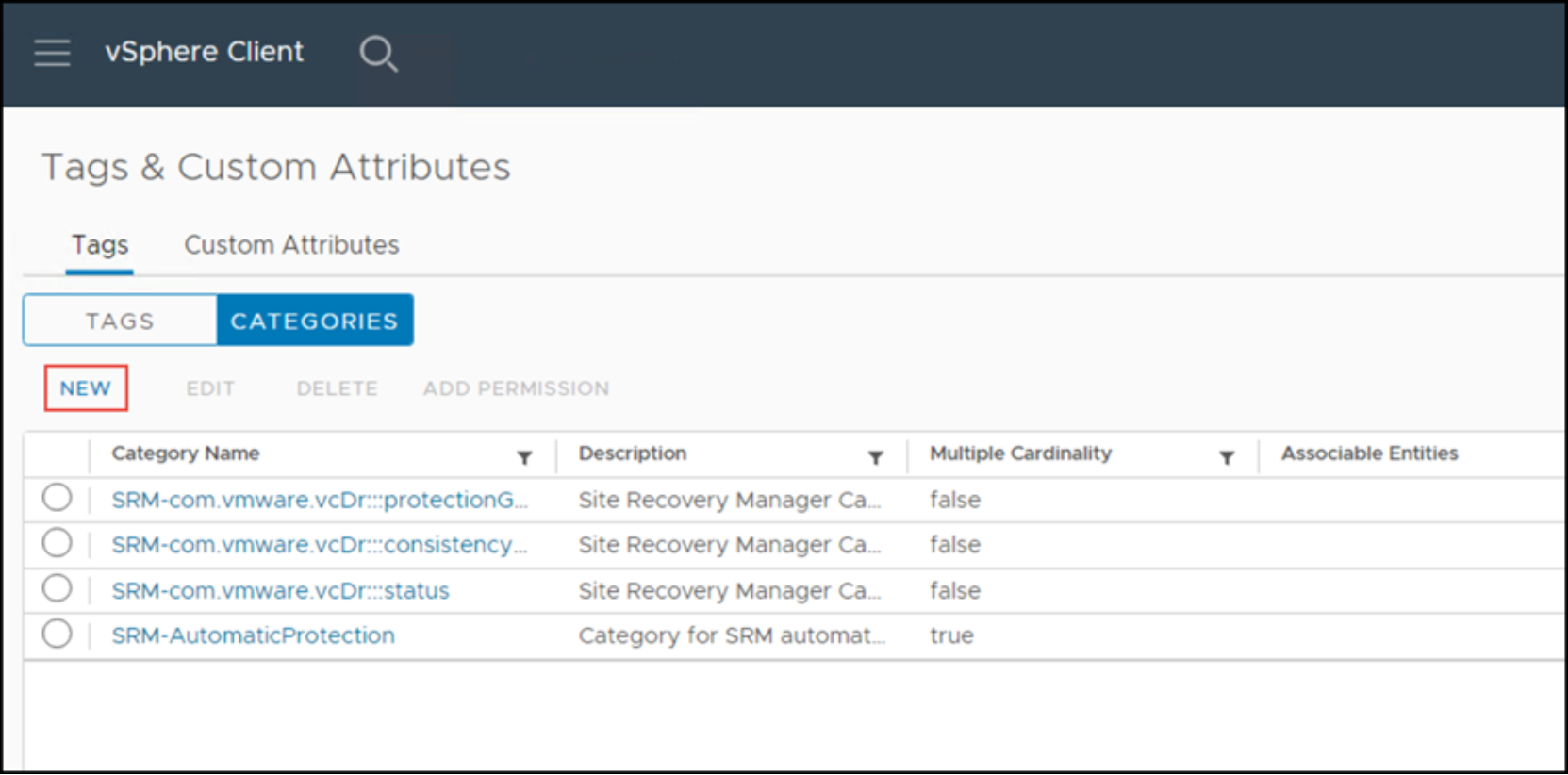
Figure 32. New category
- Enter a Name for the category and choose whether to use one or many tags.
- Optionally, add a Description.
Note: Figure 33 shows an example in which a single tag is used to avoid applying multiple options to the same datastore.
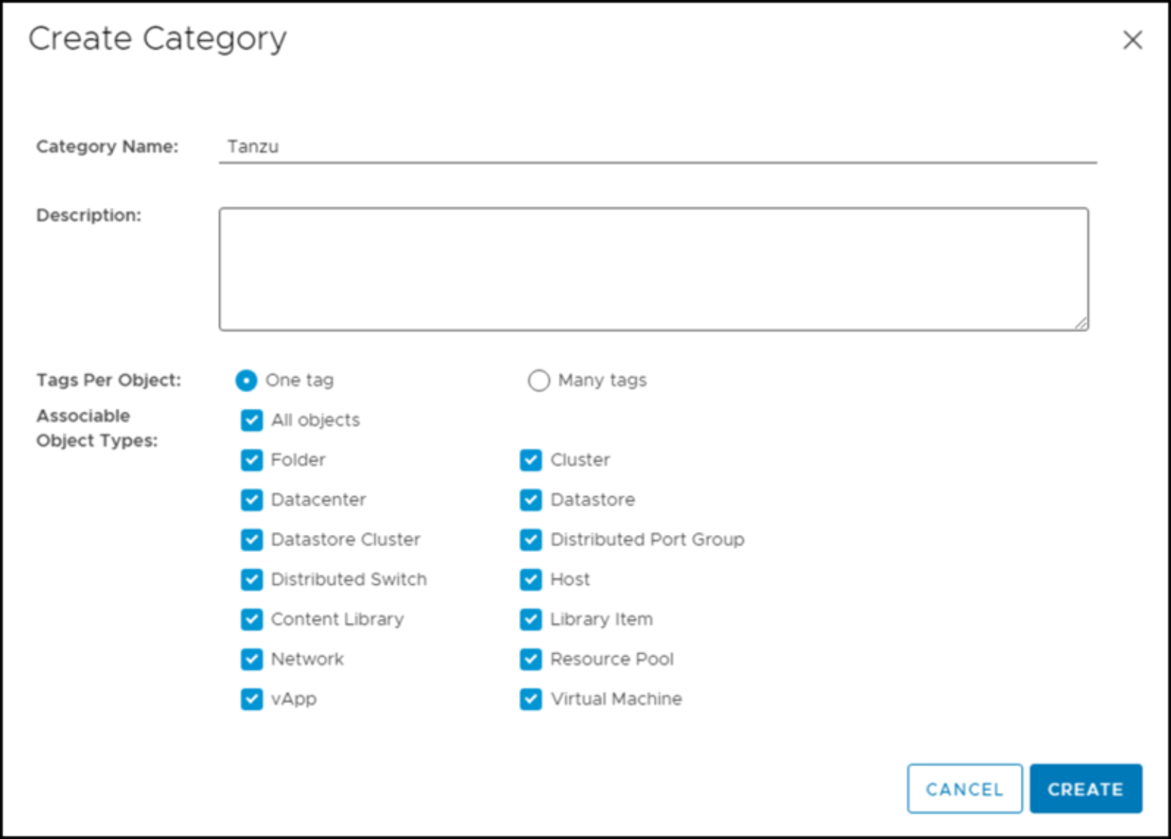
Figure 33. Create a category
Tags
Since both SDC and NVMe/TCP is used for PowerFlex volumes, two tags are necessary.
SDC
- Return to the Tags & Custom Attributes screen.
- Select the TAGS button, and then and select NEW to display the Create Tag dialog window.
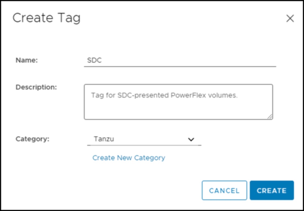
Figure 34. Add an SDC tag
- Enter a Name for the tag. This example uses SDC.
- Use the drop-down box to choose the Tanzu category previously created.
- Click Create to complete the tag.
NVME/TCP
- Return to the Tags & Custom Attributes screen.
- Select the TAGS button, and then select NEW.
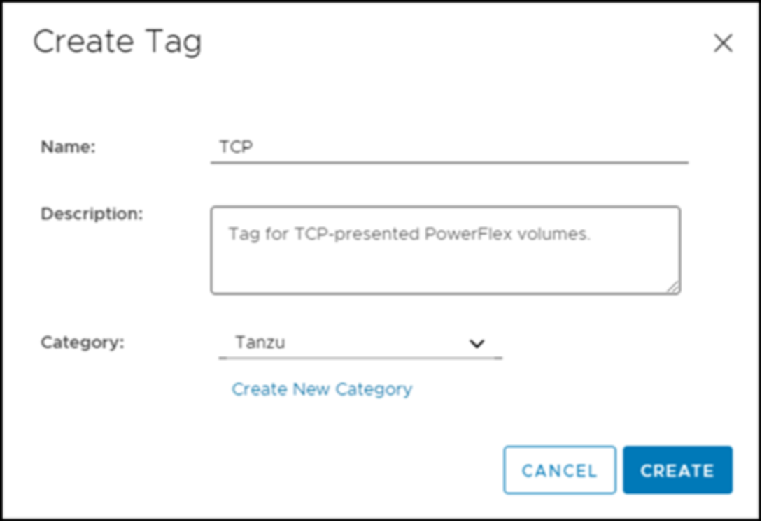
Figure 35. Add a NVMe/TCP tag
- Enter a Name for the tag. This example uses TCP.
- Use the drop-down box to choose the Tanzu category previously created.
- Select Create to complete the tag.
Datastore assignment
You can now assign the tag to the appropriate datastores. This process is manual as explained earlier, because the tags do not inherit any attributes from the array. A tag is whatever you want it to be, and it can be assigned to any number of objects.
Start by identifying the two different types of datastores on the PowerFlex volumes.
SDC
- In vSphere, go to the vCenter Datastores -> Datastores view.
- Right-click the SDC datastore and go to the Tags & Custom Attributes -> Assign Tag… option, as shown in Figure 36.
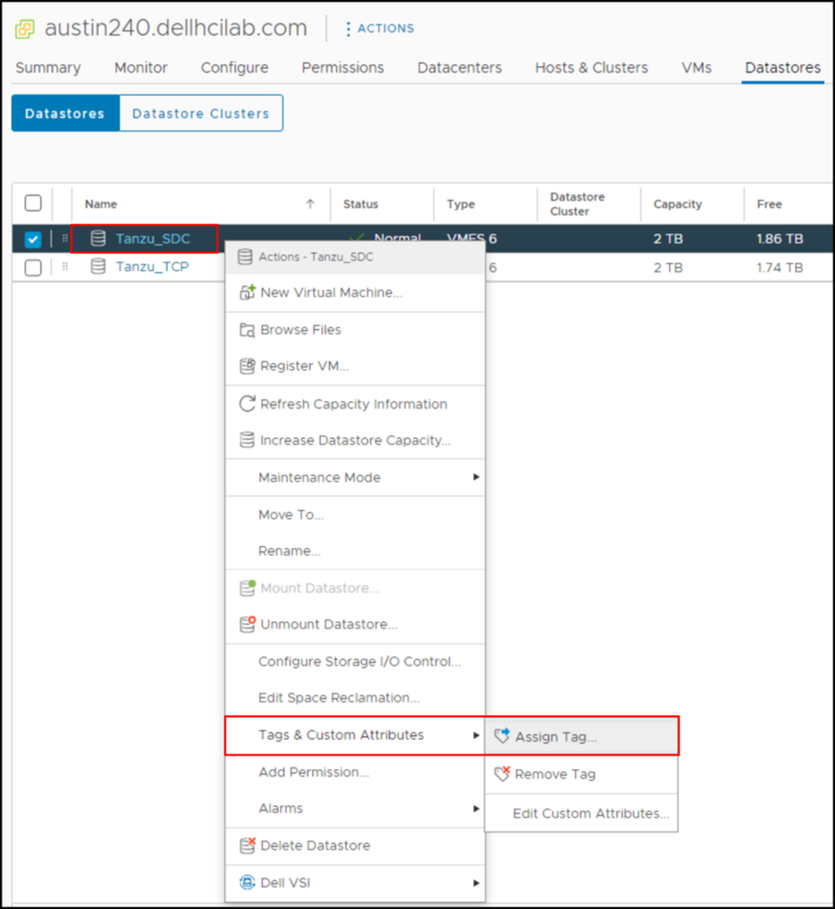
Figure 36. Assign SDC tag – Step 1
- Use the check box to select the SDC tag as shown in Figure 37.
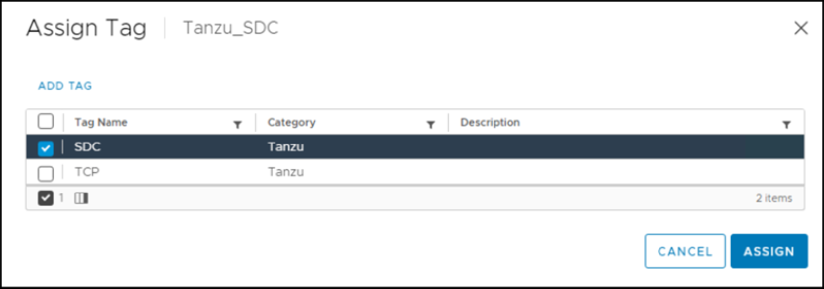
Figure 37. Assign SDC tag – Step 2
TCP
In vSphere, repeat the same process.
- Right-click the TCP datastore and go to the Tags & Custom Attributes -> Assign Tag… option.
- Use the check box to select the TCP tag.
Storage policies
The tag-based storage policy creation is the final step in the process. The SDC storage policy is shown as an example, but the TCP policy is included at the end of the process.
SDC
- In vSphere, click the hamburger menu () on the left.
- Go to the Policies and Profiles menu.
- Select VM Storage Policies as shown in Figure 38.
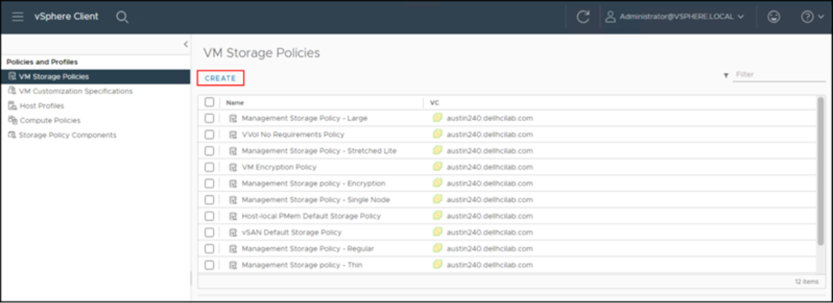
Figure 38. SDC storage policy – Step 1
- Click CREATE.
- Enter a Name (required) and Description (optional) for the policy.
- Click NEXT.
- Under the Policy structure screen, check the box next to Enable tag based placement rules, as shown in Figure 39.
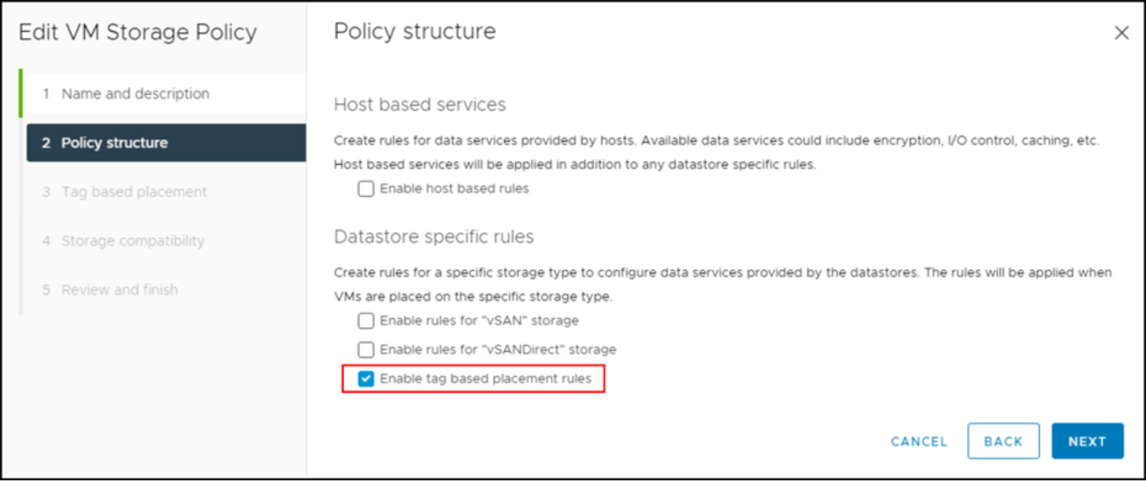
Figure 39. SDC storage policy – Step 3
- Click NEXT.
- Now that tagging is enabled, select the category that was created earlier from the drop-down box as shown in Figure 40.
Note: Doing so enables the BROWSE TAGS button.
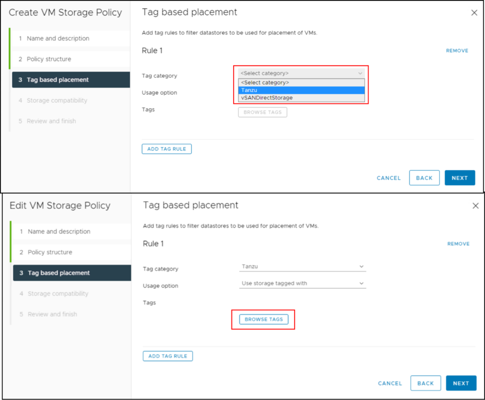
Figure 40. SDC storage policy – Step 4
- Click BROWSE TAGS.
- Use the check box next to the correct tag, and then click OK as shown in Figure 41.
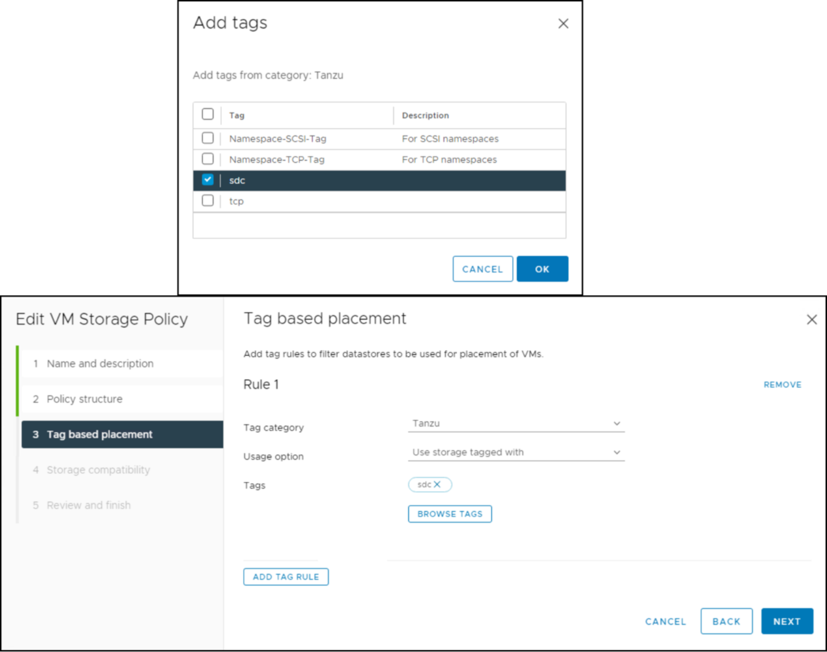
Figure 41. SDC storage policy – Step 5
- Click NEXT.
With the rule applied, VMware lists any datastores that meet the assigned criteria. In this example, the SDC tag was only put on one datastore as shown in Figure 42.
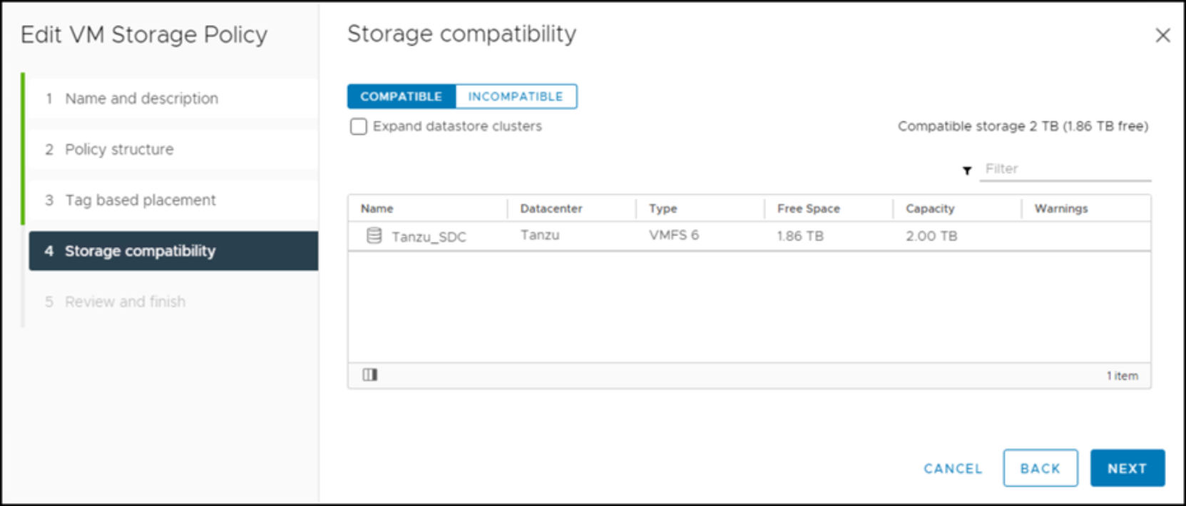
Figure 42. SDC storage policy – Step 7
- Click NEXT to reach the summary page, as shown in Figure 43.
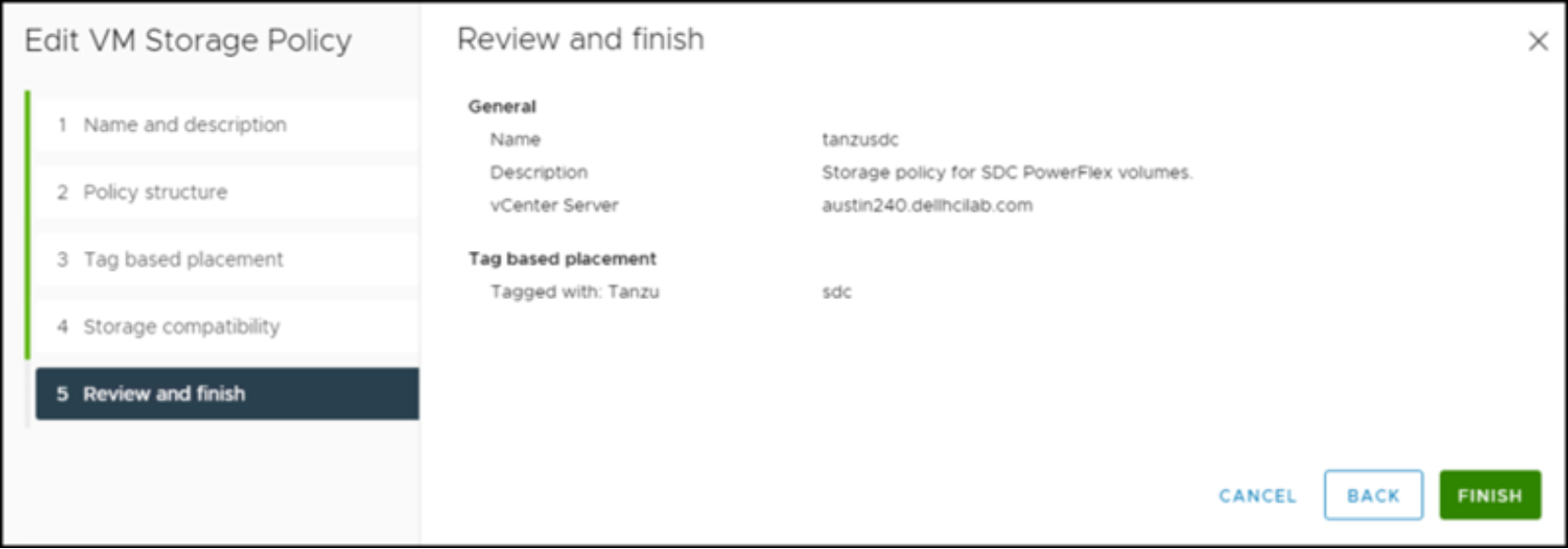
Figure 43. SDC storage policy – Step 8
- Review the selections, and then click FINISH.
TCP
The TCP storage policy is created in the same way as the SDC policy, but the tag is TCP instead of SDC. The TCP policy is shown in Figure 44.
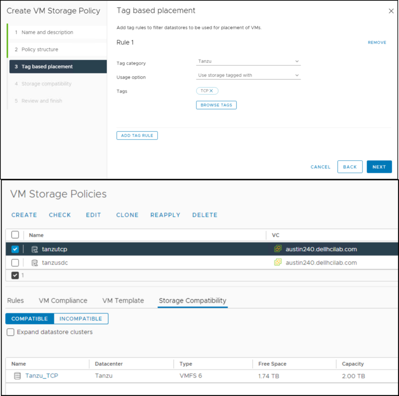
Figure 44. TCP storage policy
Namespace tags
In addition to the tags for the Tanzu infrastructure, you should create ones for the Namespaces. The Namespaces enable the administrator to set resource and object limits for the chosen users. Specific Kubernetes clusters and Storage Policies are assigned to these namespaces. To assign the storage policies, you must setup the tags and assign them to datastores.
The two tags for this Tanzu environment are shown in Figure 45 using the same Tanzu category. These tags are array-agnostic as this storage setup has more arrays than PowerFlex. Therefore, there are tags for:
- Any SCSI-presented storage
- Namespace-SCSI-Tag
- Any NVMe/TCP-presented storage (Namespace-TCP-Tag)
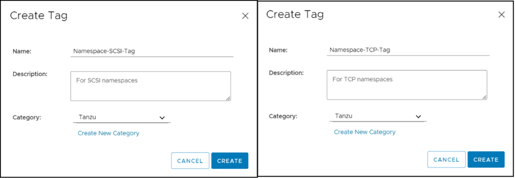
Figure 45. Namespace tags
After creating the tags, associate them with any datastores that are used for persistent volumes, as described in Provision storage.
Namespace storage policies
These tags are now used for the namespace storage policies. Since the wizard was covered previously in VMware storage policies, Figure 46 and Figure 47 show the compatible datastores (with tag applied) and the results.
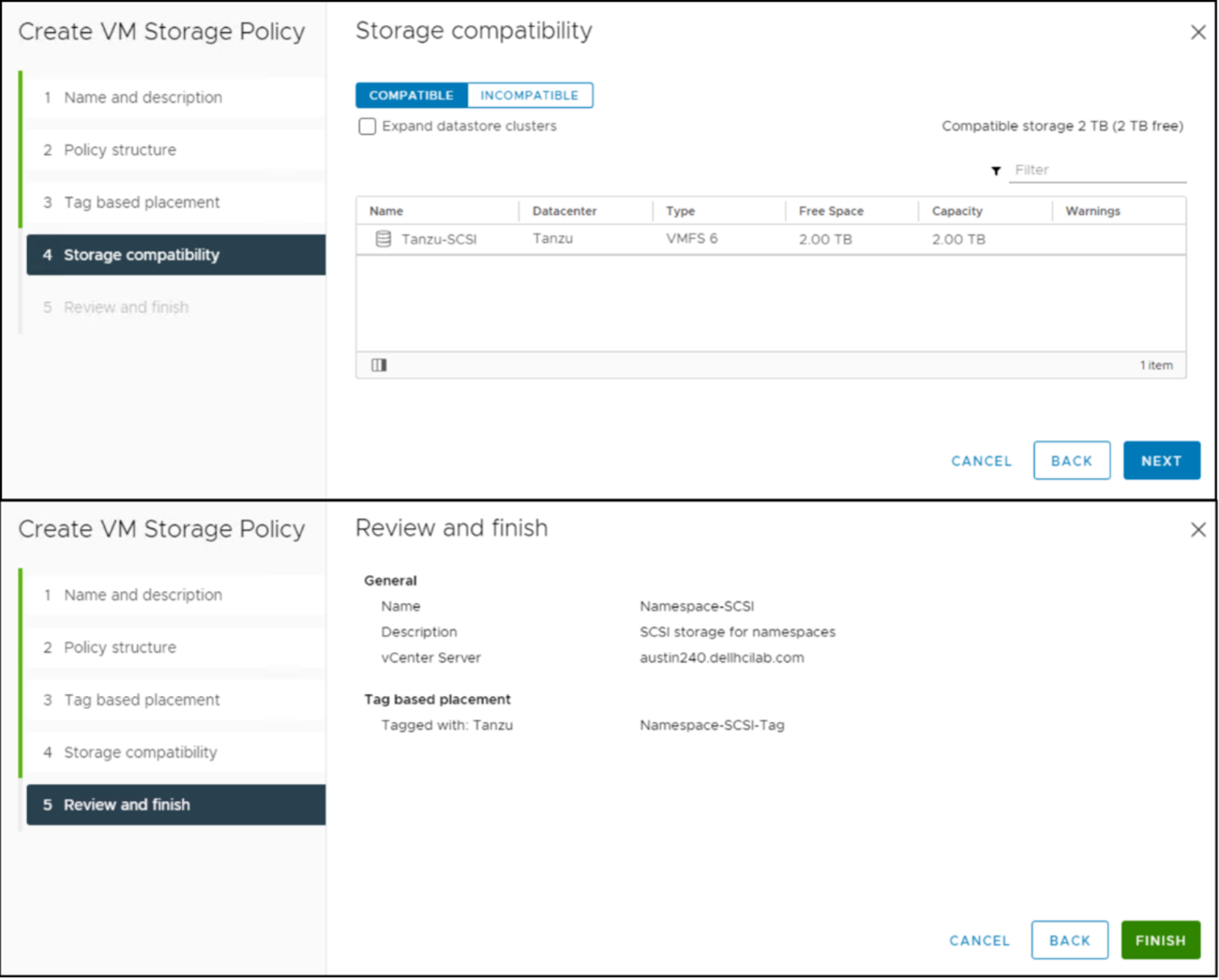
Figure 46. Storage policy Namespace – SCSI
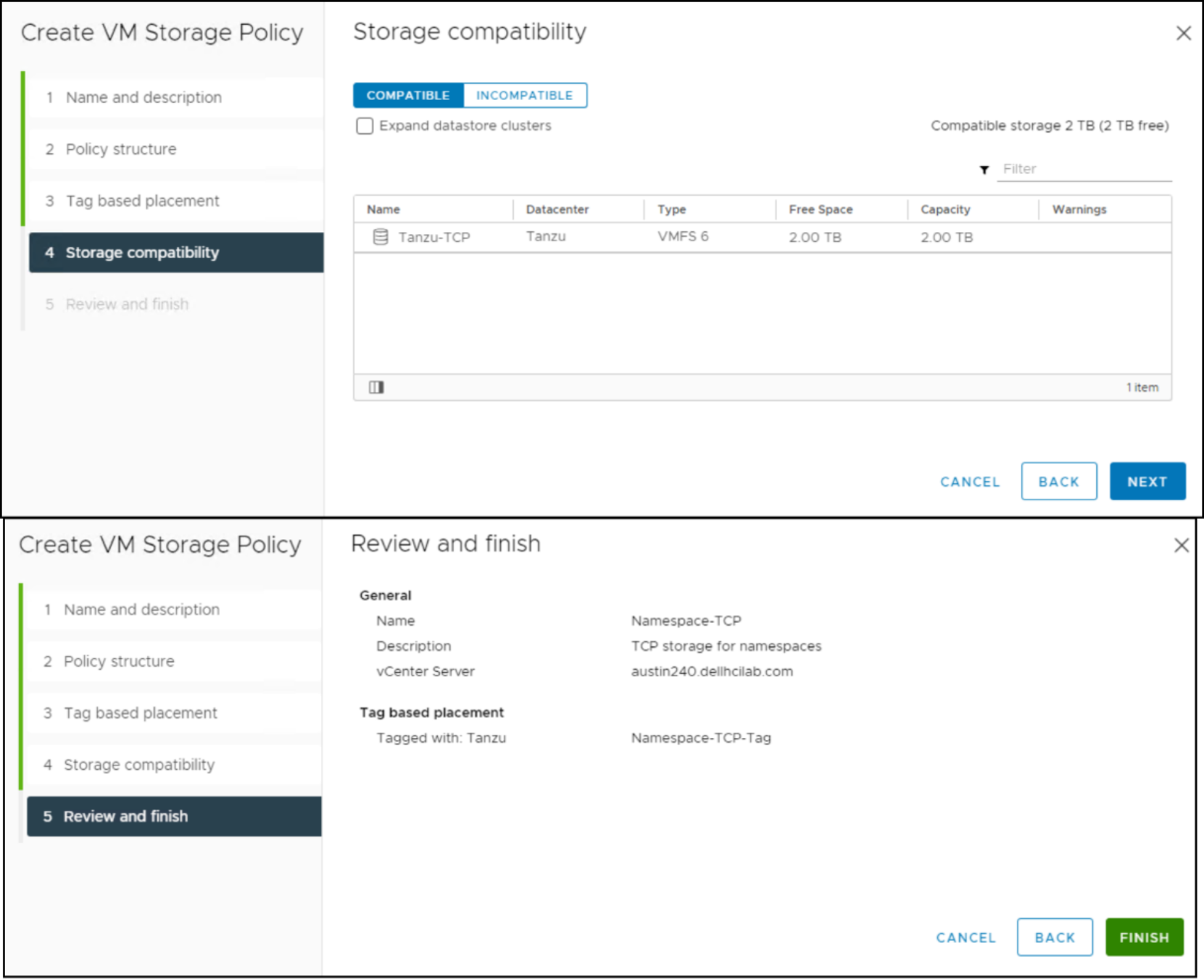
Figure 47. Storage policy Namespace – TCP
Adding a content library
Introduction
For Tanzu to create the TKG Clusters, it must have access to the online templates for the virtual machines. This access is gained through the addition of a content library. A content library is a container object for VM templates and other types of files. These files can be ISO images, text files, or any other type of file that users may want to share across a VMware environment.
A content library can be local or subscribed. A local library is one in which the VMware administrator uploads and controls access to the files through publishing. A subscribed library attaches to an existing published library to which the VMware administrator has no control. The owner of the subscribed library controls publishing.
Content library configuration
This procedure describes adding the TKG content library in preparation for the Tanzu installation.
- In vSphere, click the hamburger menu () on the left.
- Go to the Content Libraries option. The New Content Library dialog window displays as shown in Figure 48.
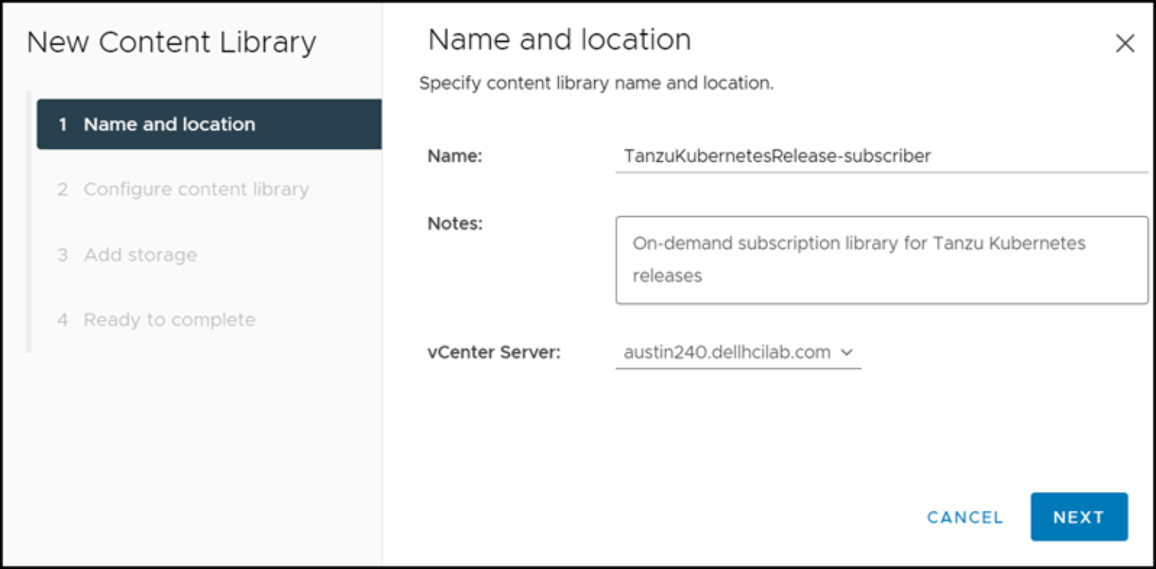
Figure 48. Add content library – Step 2
- Enter a Name (required), Notes (optional), and vCenter Server if not already defaulted.
- Click NEXT to advance to the Configure content library dialog window.
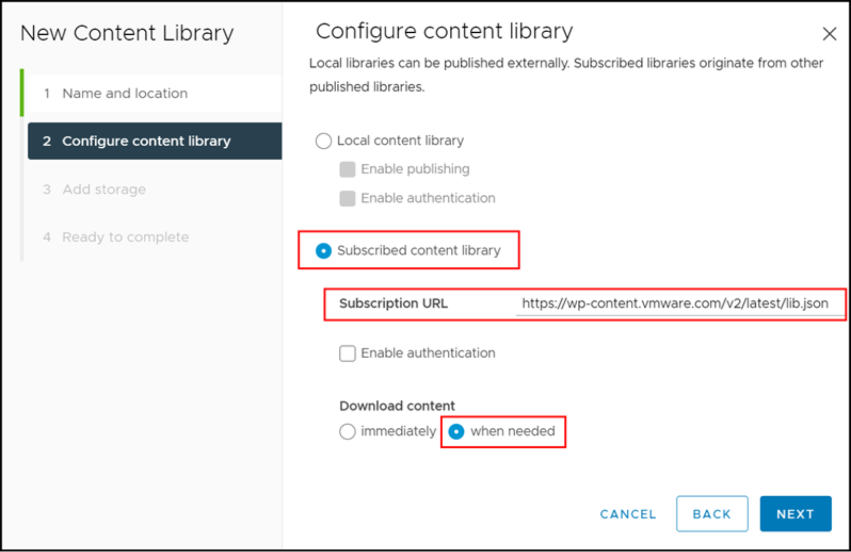
Figure 49. Add content library – Step 3
- Select the Subscribed content library radio button.
- Enter the Subscription URL that VMware provides.
- Select the Download content -> when needed radio button.
Note: Doing so ensures that VMware gathers only what it requires when it deploys the TKG Clusters.
- Click NEXT. An authenticity verification pop-up dialog opens.
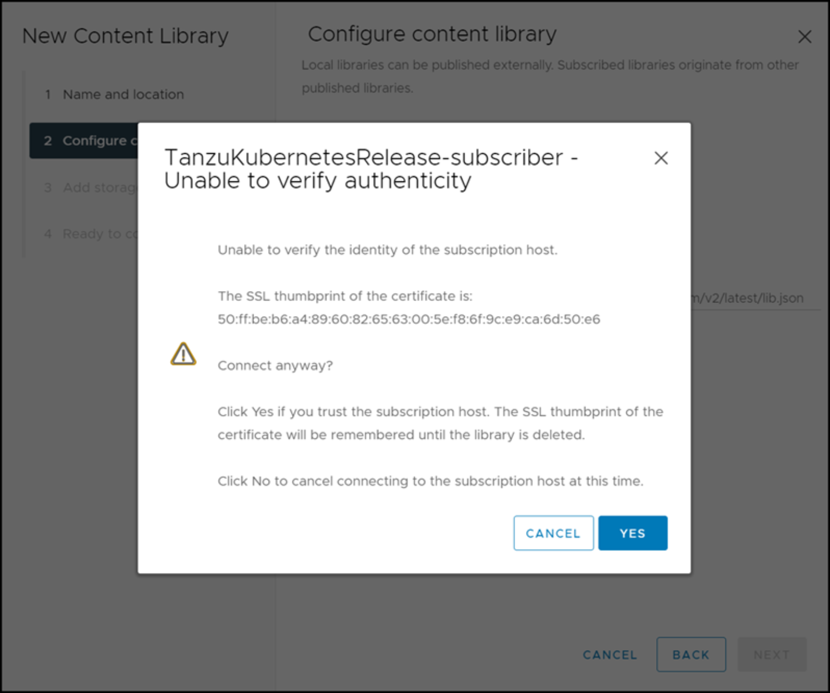
Figure 50. Add content library – Step 4
- Click YES to verify the authenticity of the library.
- In the next dialog, use the drop-down box to select OVF default policy as the security policy.
- Leave the Apply Security Policy checkbox selected.
- Click NEXT to advance to the Add storage dialog window as shown in Figure 51.
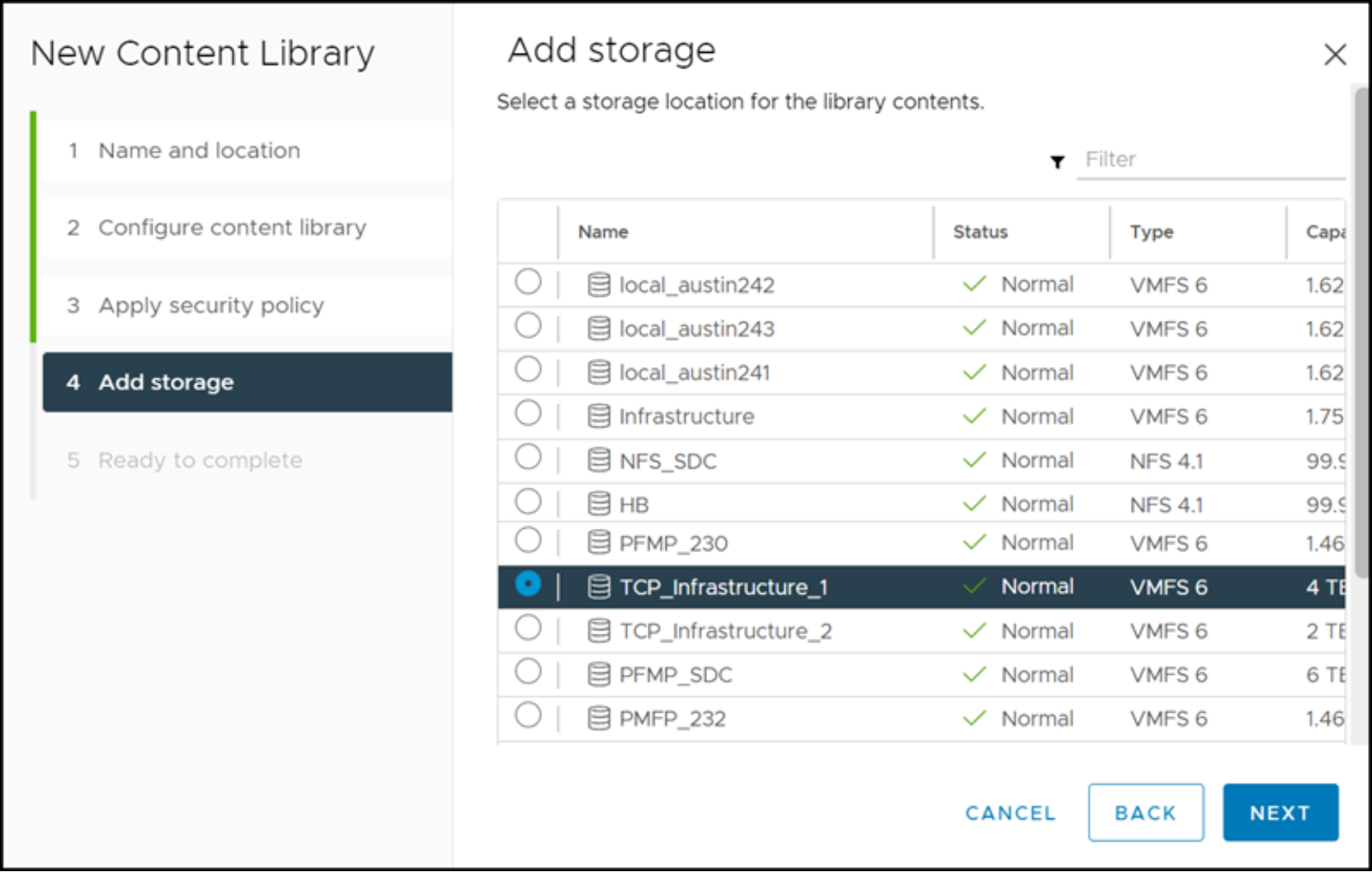
Figure 51. Add content library – Step 6
- Choose a datastore where the library content is stored.
Note: Since the images are on-demand, the storage usage should be minimal. The type of datastore is not relevant. In this example, a PowerFlex datastore that is presented using NVMe/TCP is selected.
- Select NEXT to continue.
- Review all the settings in the summary page, and then click FINISH.
The library is now added and available.
vSphere with Tanzu implementation
Introduction
NSX load balancer
Since there are different networking options the user may choose, this guide does not go into the detailed installation of the NSX Load Balancer. Both HA Proxy and NSX Load Balancer enable most of the Tanzu functionality that customers use, while NSX-T is a complete solution.
Installing the NSX Load Balancer is straightforward. It is deployed as a single VM using an OVA file. The single VM, once deployed, can be expanded into a multinode cluster for production environments as was the case in this solution. The three nodes are shown in Figure 52.
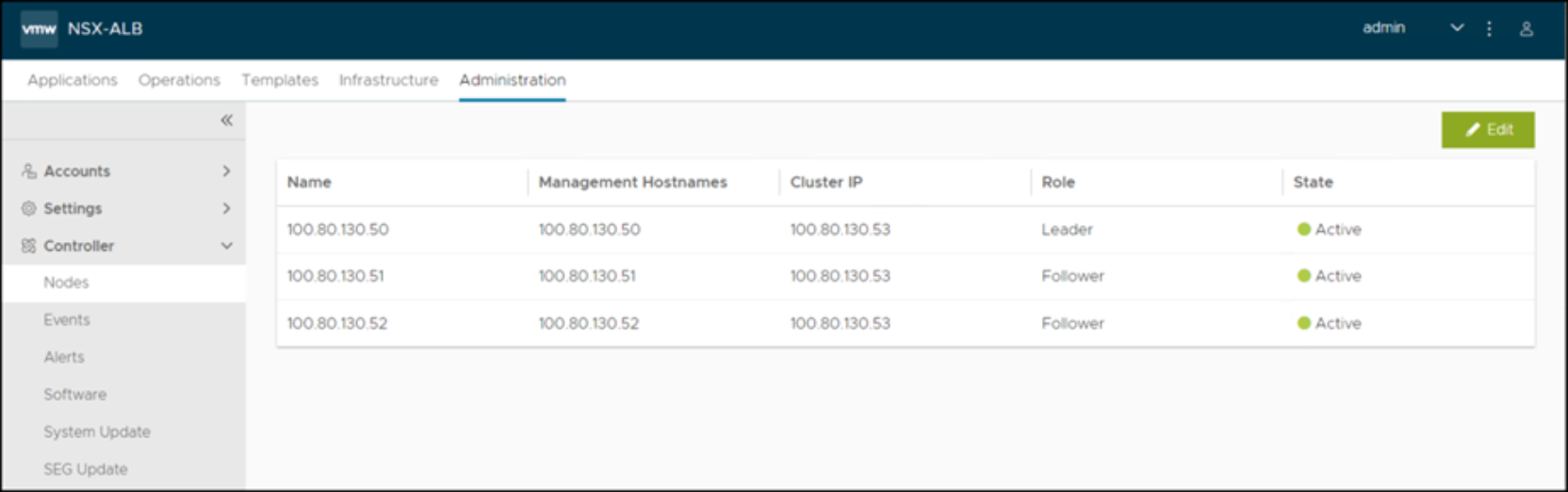
Figure 52. Multinode NSX-LB implementation
VMware offers step-by-step instructions for configuring the NSX Load Balancer in preparation for use with Tanzu. These instructions were followed for this guide:
Tanzu
With all prerequisites completed including the NSX Load Balancer installation, users can configure Tanzu.
vSphere with Tanzu is not truly enabled until a Supervisor Cluster is installed. The Supervisor Cluster is at the heart of Tanzu, providing the necessary resources for the environment. A Supervisor Cluster is created with the Workload Management screen of the vSphere Client. It is associated directly with a cluster within vSphere which has at least two ESXi hosts. The Supervisor Cluster, once created, enables the user to run Kubernetes workloads. VMware portrays the architecture in the following simple diagram in Figure 53.
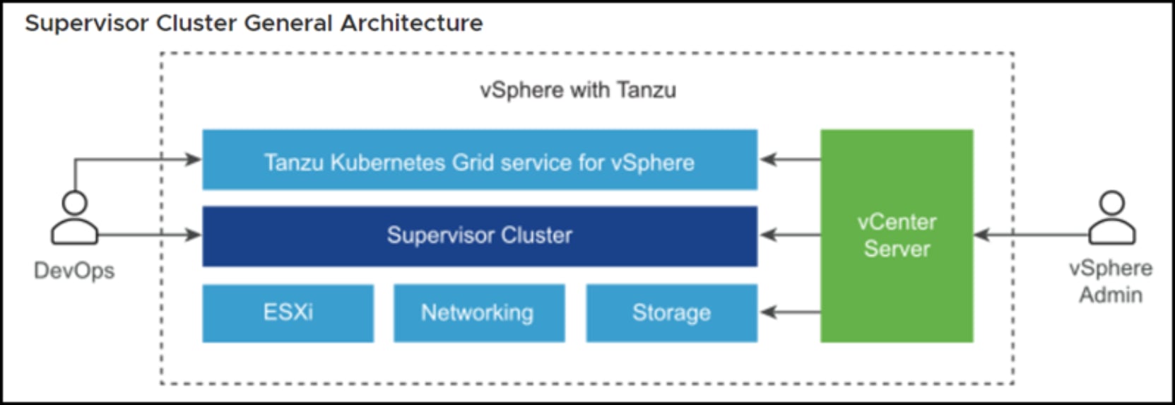
Figure 53. Supervisor Cluster
ESXi houses additional components for Tanzu, as detailed in Figure 54. There is a Spherelet which is a kubelet that is ported to ESXi, which enables the host to be part of a Kubernetes cluster. Three Kubernetes control planes are also present in total, even if there are only two ESXi hosts that make up a Kubernetes cluster. The CRX, or Container Runtime Executive, is for vSphere Pods. Finally, not listed here are the essential two modules which makes Kubernetes cluster provisioning possible: The Cluster API and VMware Tanzu Kubernetes Grid Service.
Note: Spherelets and the vSphere Pods are not supported with vSphere Networking as used in this guide.
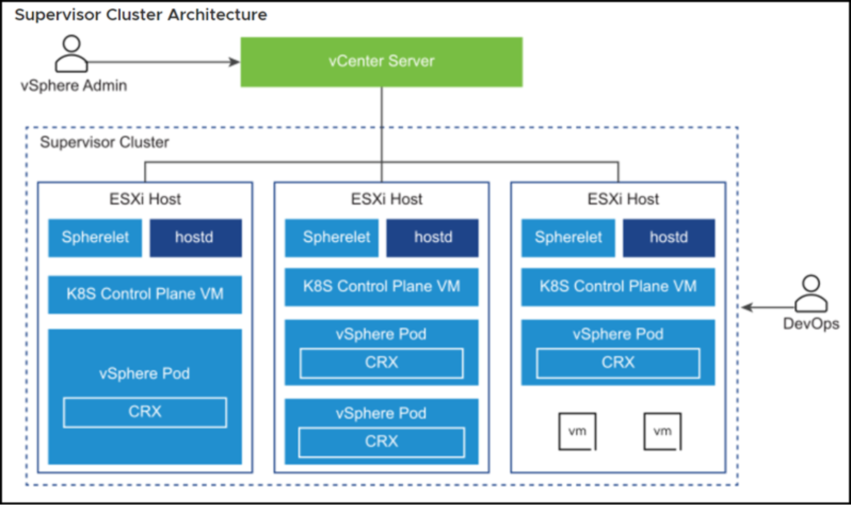
Figure 54. Supervisor Cluster ESXi detail
Finally, VMware has three different ways that the Tanzu Kubernetes Grid helps the user to manage the environment. At a high level, these methods are:
- Tanzu Kubernetes Grid Service—It is what provisions the clusters. It includes a Cloud Provider Plugin (NCP in diagram). Most importantly, the Kubernetes cluster passes requests for persistent volumes (for example, on PowerFlex datastores) to the Supervisor Cluster. This service is integrated with VMware Cloud Native Storage (CNS).
- Cluster API—Developers can use a tool more familiar to them to accomplish the same as what the UI would offer.
- Virtual Machine Service—It manages the life cycle of the control plane and worker node VMs hosting a Tanzu Kubernetes cluster.
These components are displayed in Figure 55.
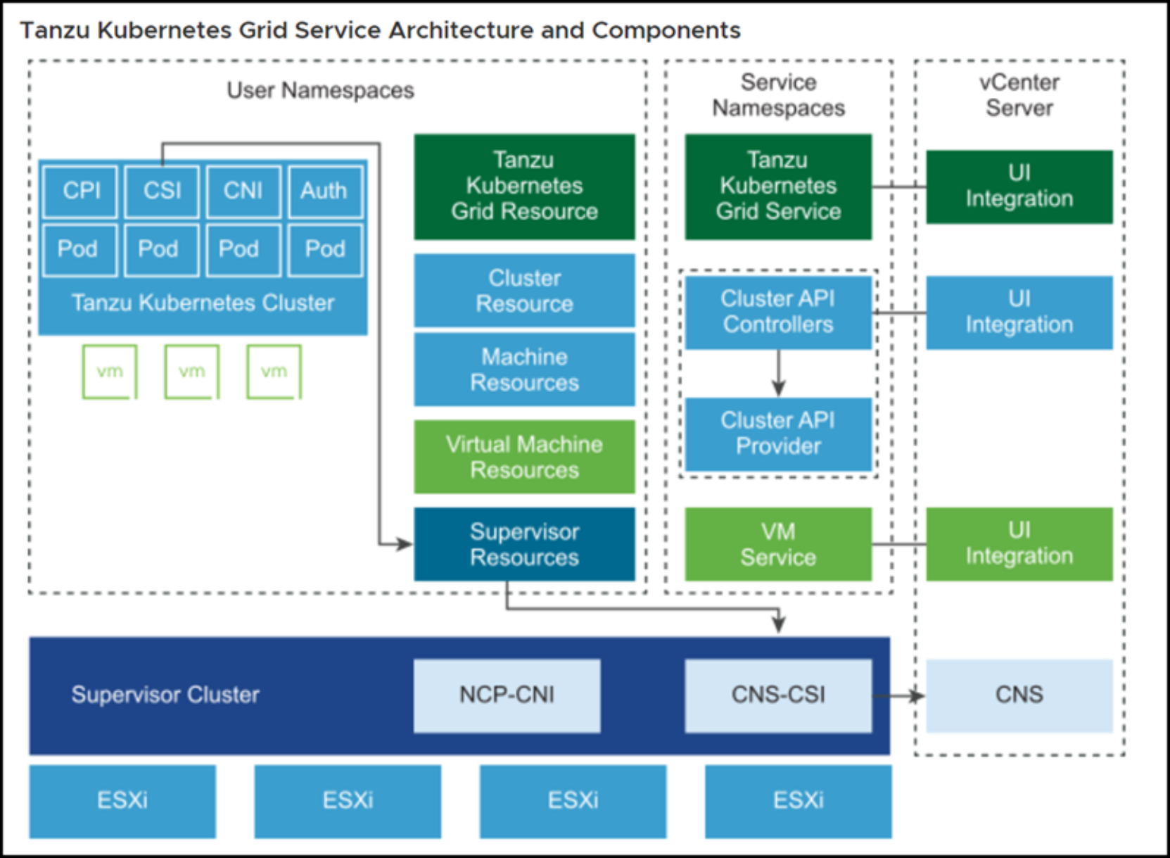
Figure 55. Tanzu Kubernetes Grid Service architecture
CNI and CNS
Storage is essential for using PowerFlex with Tanzu. This section provides a detailed discussion about the Container Storage Interface (CSI) and Cloud Native Storage (CNS).
CNS enables customers to consume persistent storage in Kubernetes, while providing automation or life cycle management. VMware offers the infographic in Figure 56, which shows the CNS components. VMware uses a CSI, or Container Storage Interface, to provision storage from various sources. A CSI is an implementation of the CSI specification which dictates how to connect storage to the orchestration tools in containers.
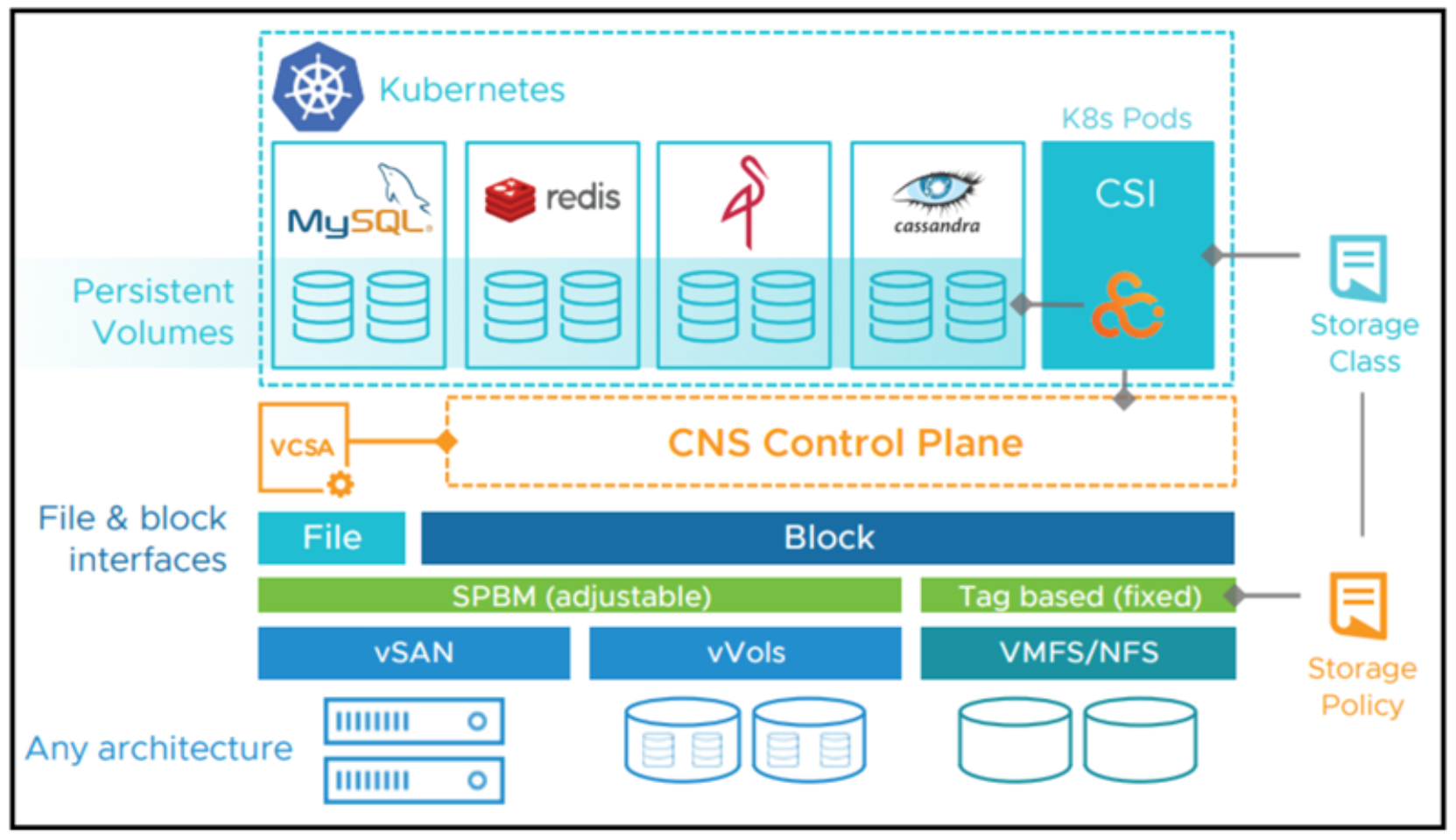
Figure 56. CNS and CSI in vSphere
The vSphere CSI uses Storage Policy Based Management (SPBM), or storage policies with storage classes, to create persistent storage for Kubernetes. As shown in the diagram, that storage could be anything from vSAN to vVols, VMFS to NFS.
First Class Disks
Volumes that are created with vSphere CSI are known as First Class Disks, or FCDs. What makes FCDs special is that unlike most disks in vSphere, these disks do not have to be associated with a VM. A .vmdk in vCenter is considered based on the VM to which it is attached.
Through editing the VM users can expand the disk, delete it, or even temporarily remove it, and add it to another VM. However, its life is associated with another object, unlike with FCDs. A First Class Disk has its own life cycle which can be controlled outside of the VM. Users can expand it, snapshot it, or delete it without it ever being tied to a VM.
Cloud Native Storage
Although VMware presents CNS as all the components in Figure 56, it really has two parts:
- A vSphere volume driver for Kubernetes (vSphere CSI)
- The integration into vCenter shown in Figure 57
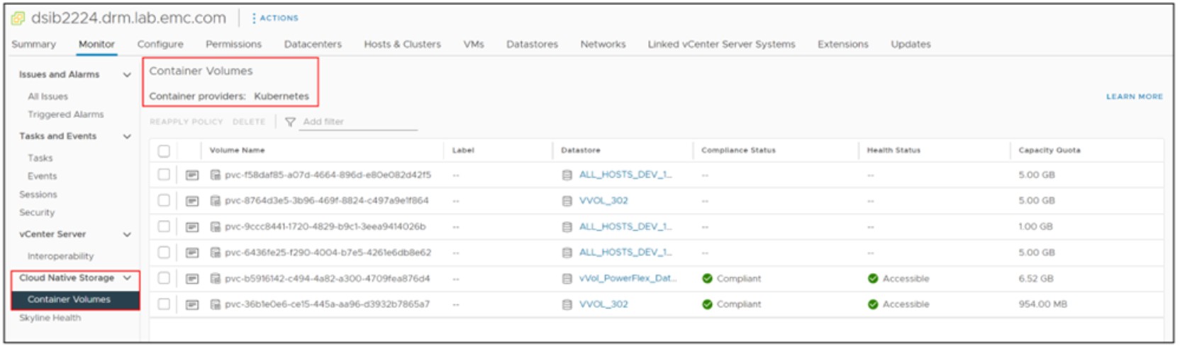
Figure 57. CNS vCenter integration
The volume driver consists of two pieces; a syncer and the vSphere Container Storage Interface (CSI) driver. CNS controls all aspects of volume provisioning with the storage control plane. It handles the entire life cycle – creation, deletion, and so forth, including snapshots, clones, and general health. One concept that is essential to this model is that these volumes are independent of the life cycle of VMs. This independence is only possible with the FCDs.
Storage vendor CSIs
While the vSphere CSI does not know or care about the underlying storage, vendor CSIs are designed to provision only from their own storage. By design, these CSIs are not part of the VMware CNS. However, they can co-exist in the same Kubernetes environment. With the vSphere CSI, it is not possible to provision a device directly from say the PowerFlex array to a cloud-native application.
Any vSphere CSI-provisioned device from PowerFlex 4.0.x is a .vmdk in a VMFS or NFS datastore. Tanzu does not permit implementation of vendor CSI drivers on the Supervisor Cluster. It may be technically possible to use a vendor CSI driver on a Tanzu Kubernetes cluster. However, VMware would not support the steps that would be required to do so. VMware locks down the virtual machines that make up the cluster as seen in Figure 58.
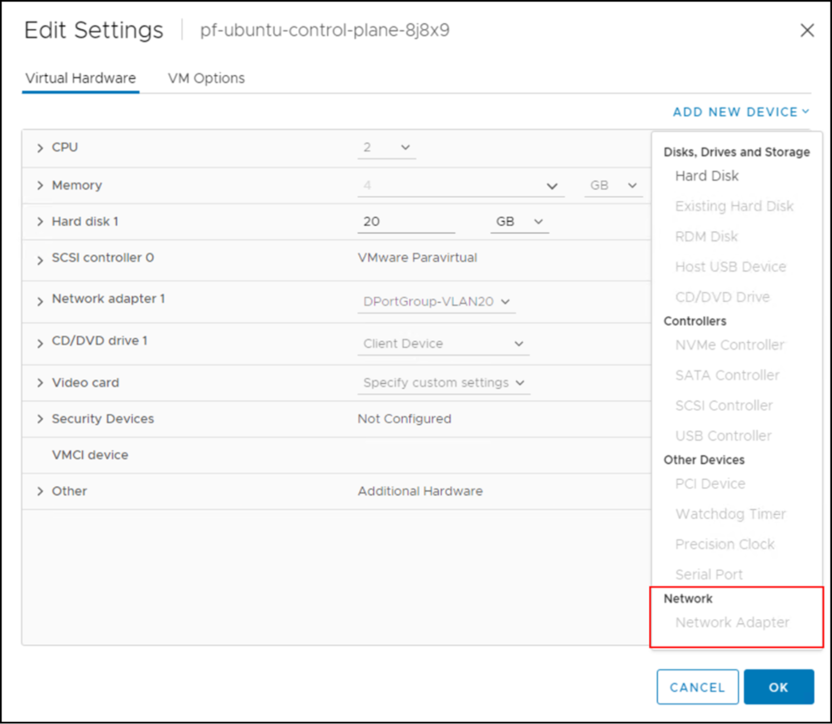
Figure 58. Tanzu Kubernetes cluster node
Users must add network interface controllers and gain access to the operating system to install the SDC driver to use the PowerFlex CSI. NVMe/TCP is not supported with the CSI. Since the VM is purposely locked-down by VMware, anything that is done to unlock it, by definition, would be unsupported. Dell Technologies advises customers that want to use the PowerFlex CSI to install Kubernetes on VMs that are not part of the Tanzu environment.
Configure workload management
The Supervisor Cluster is configured within vCenter. All steps and images are included as the wizard is likely new for most users.
- In vSphere, click the hamburger menu () on the left.
- Go to the Workload Management option.
- Select the Supervisor Clusters tab, and then click ADD CLUSTER.
Figure 59 shows an existing Supervisor Cluster, named Management. This example adds another Supervisor Cluster. Each Supervisor Cluster is associated with a vSphere Cluster of at least two ESXi hosts.
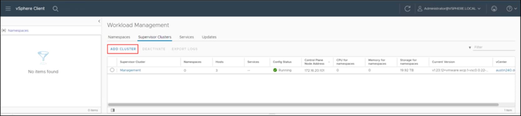
Figure 59. Workload Management – Add Cluster
If there is only a single vCenter it defaults automatically, as shown in Figure 60.
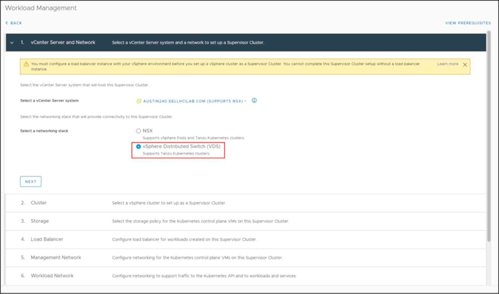
Figure 60. Workload Management – Step 1
- Select the networking stack, as shown in Figure 61.
Note: vSphere Networking is being used in this example. For VDS, a load balancer must already be installed. The wizard requires users to indicate which one in a later step.
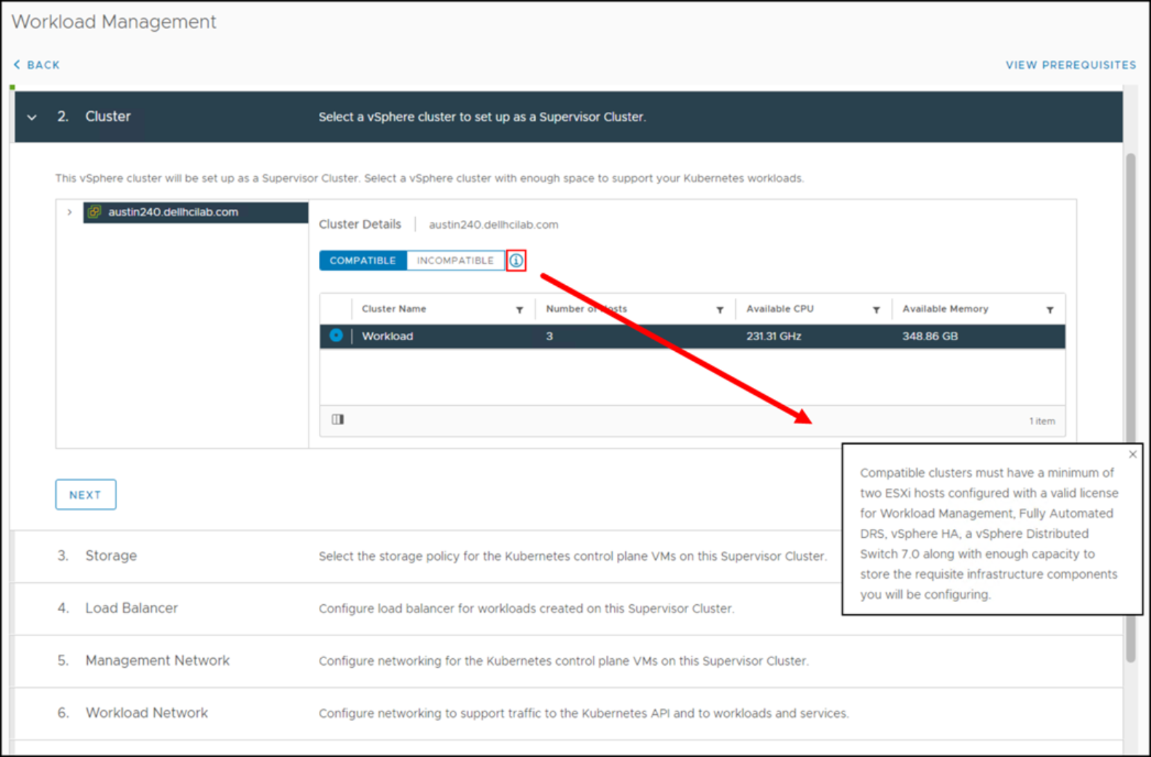
Figure 61. Workload Management – Step 2
- Select a cluster. In this example, there is one remaining cluster with three ESXi hosts.
- Select the information bubble next to the COMPATIBLE button. VMware displays a warning that a minimum of two ESXi hosts are required to create a Supervisor Cluster.
- Use the drop-down box to select a previously created storage policy, either for SDC or NVMe/TCP (as covered in VMware storage policies), as shown in Figure 62.
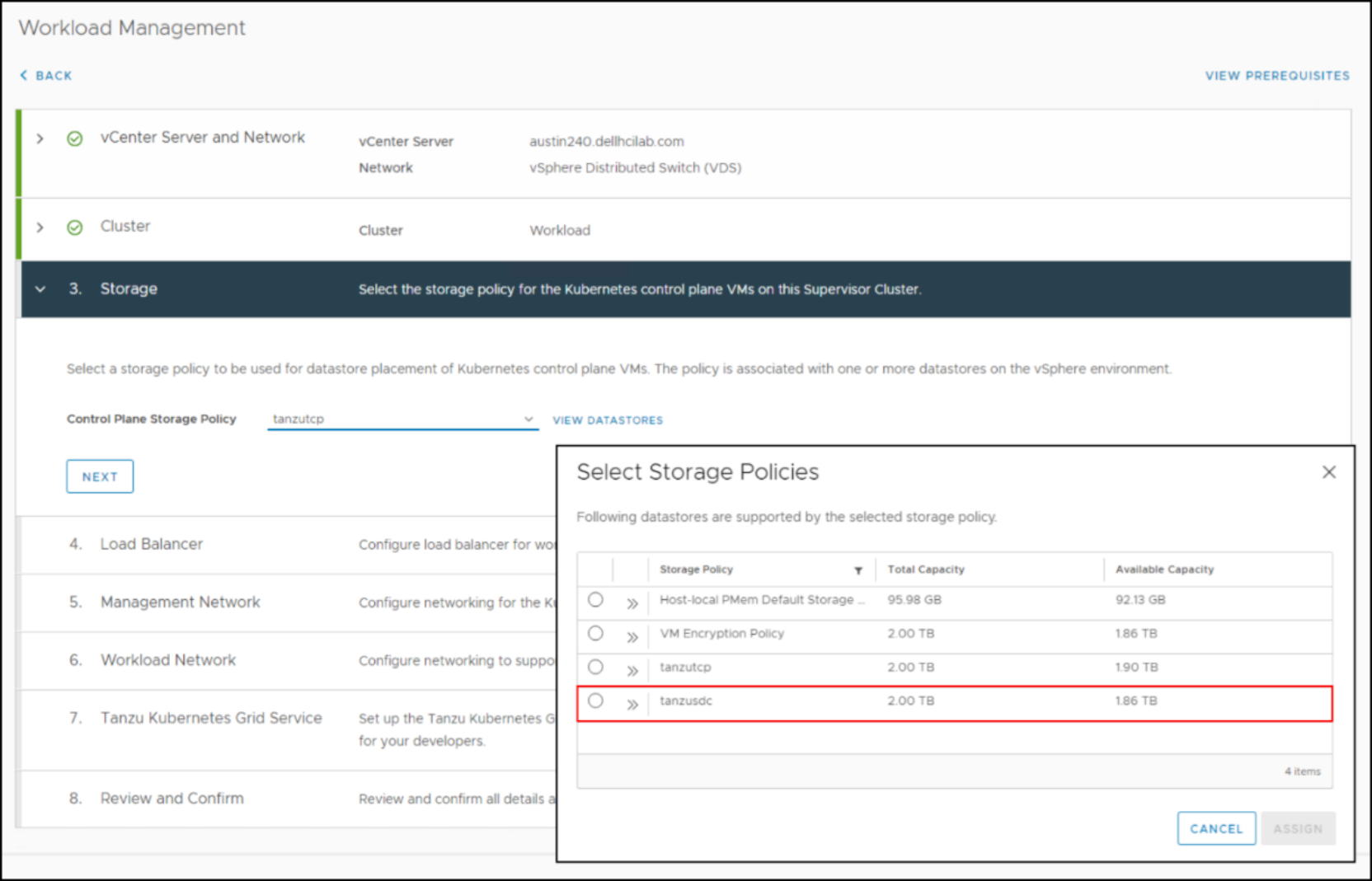
Figure 62. Workload Management – Step 3
Figure 63 indicates that all files that are related to this Supervisor Cluster should be stored in datastores that are tagged with the TCP tag.
- Select the radio button next to the policy. In this example, the tanzutcp storage policy is selected.
- Click ASSIGN to progress to the Load Balancer dialog.
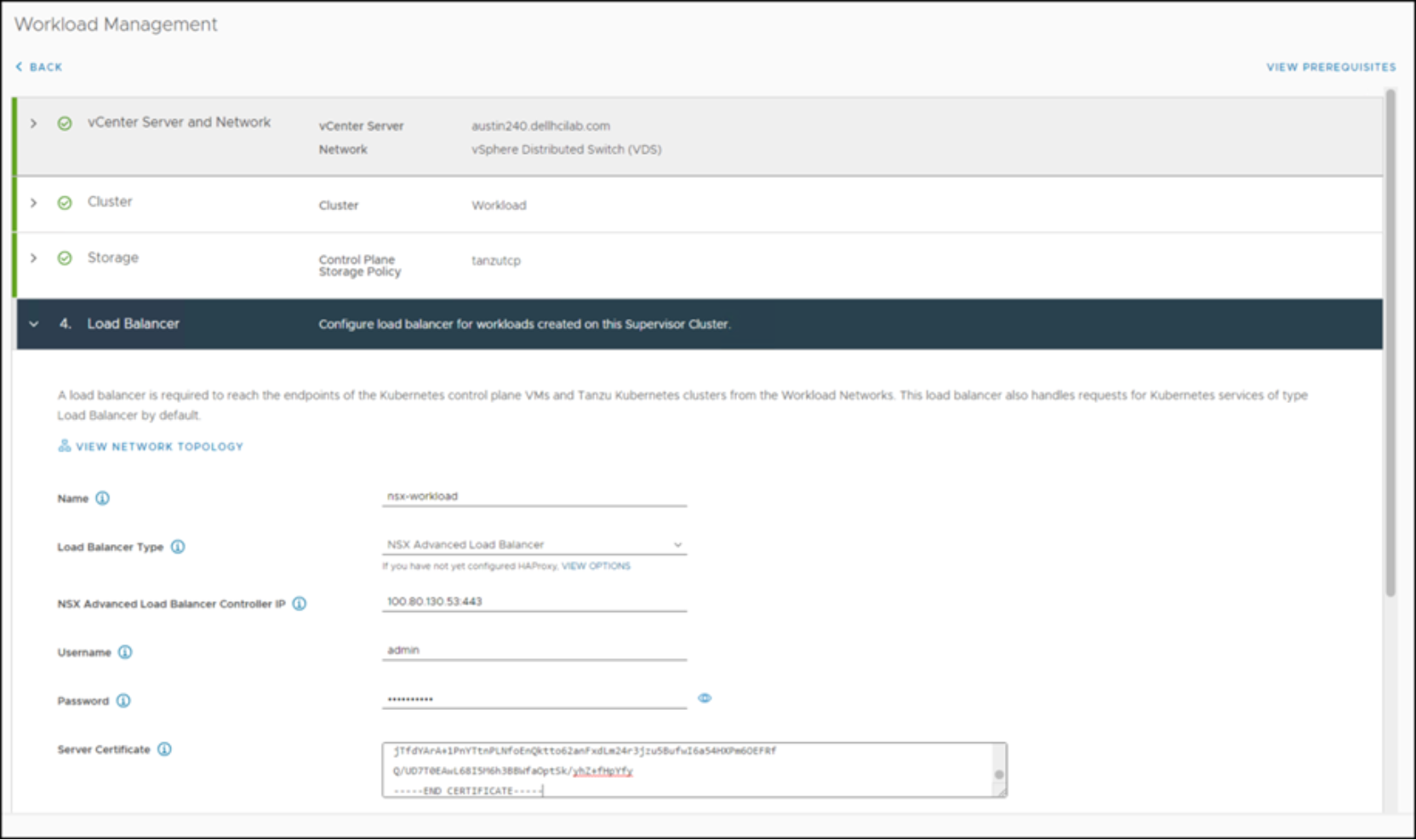
Figure 63. Workload Management – Step 4
The previously created NSX Advanced Load Balancer (ALB) information is required for this step.
- Provide a Name for the ALB.
Note: The name is only an identifier. It is not intended to resolve to an IP, for example.
- Select ALB for the Load Balancer Type.
- Enter the controller IP address. If the ALB is a cluster, use the VIP that was configured when the ALB was installed.
- Enter a Username and Password.
- Paste the Server Certificate into the box that was generated in the ALB.
Note: The certificate information is available within the NSX-ALB interface under Templates -> Security -> SSL/TLS Certificates.
- Expand the Management Network dialog, as shown in Figure 64.
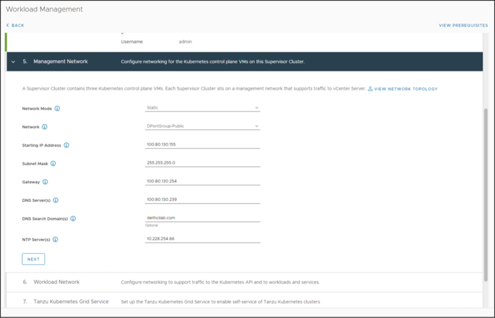
Figure 64. Workload Management – Step 5
- Input the Management Network by selecting either DHCP or Static under Network Mode. In this example, a static configuration is used which necessitates entering all the fields.
- Since a Supervisor Cluster is three nodes, the provided Starting IP Address is the first node.
- The second and third IP addresses are the following two IPs in sequence.
- Expand the Workload Network, as shown in Figure 65.
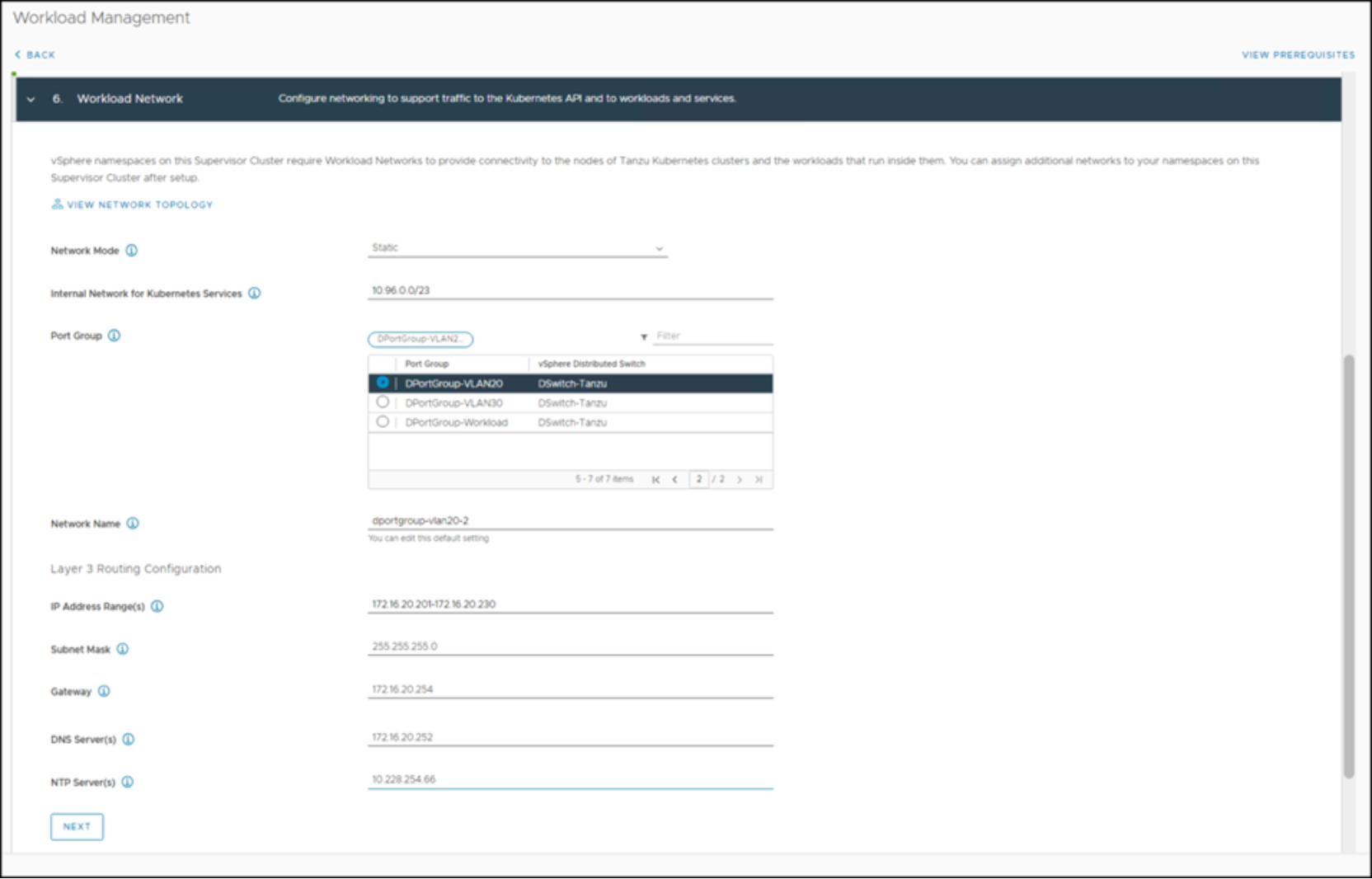
Figure 65. Workload Management – Step 6
The Workload Network is used to communicate with future Kubernetes clusters. Generally, this network is an internal network running on its own VLAN, but it must be able to route to the Management Network. Both static and DHCP routes are supported for the Network Mode.
- Select the Network Mode.
- If using static mode, the CIDR for the Internal Network for Kubernetes Services can be left as default.
- Enter a Network Name. As with ALB, the name is only an identifier.
Note: Be sure to supply enough IP addresses in the IP Address Range to satisfy the intended Kubernetes cluster or clusters.
- Click NEXT to progress to the Content Library dialog, as shown in Figure 66.
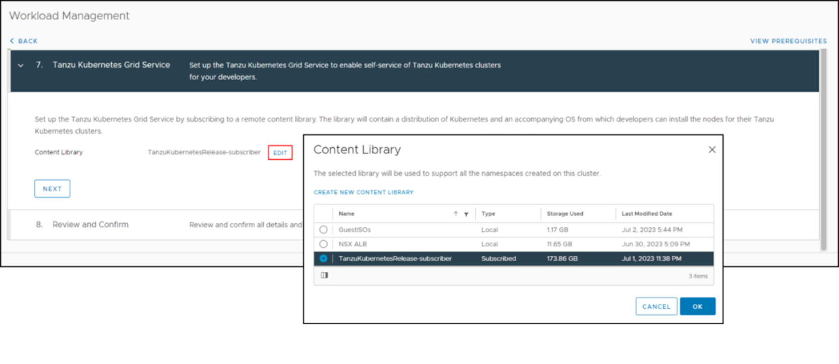
Figure 66. Workload Management – Step 7
- Add the content library that was created in the section Adding a content library.
Doing so enables the Supervisor Cluster to deploy Kubernetes clusters.
- Click OK.
- Click NEXT to progress to the Review and Confirm dialog, as shown in Figure 67.
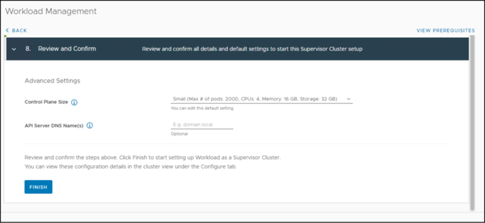
Figure 67. Workload Management – Step 8
- Ensure that all information is correct before proceeding.
Note: If changes are required, then each step in this section must be repeated. You cannot update a single item.
- Once all information is confirmed, click FINISH.
- While the cluster is under configuration, you can review them by selecting the hyperlink (for example, 1) in the Config Status column. The output is shown in Figure 68.
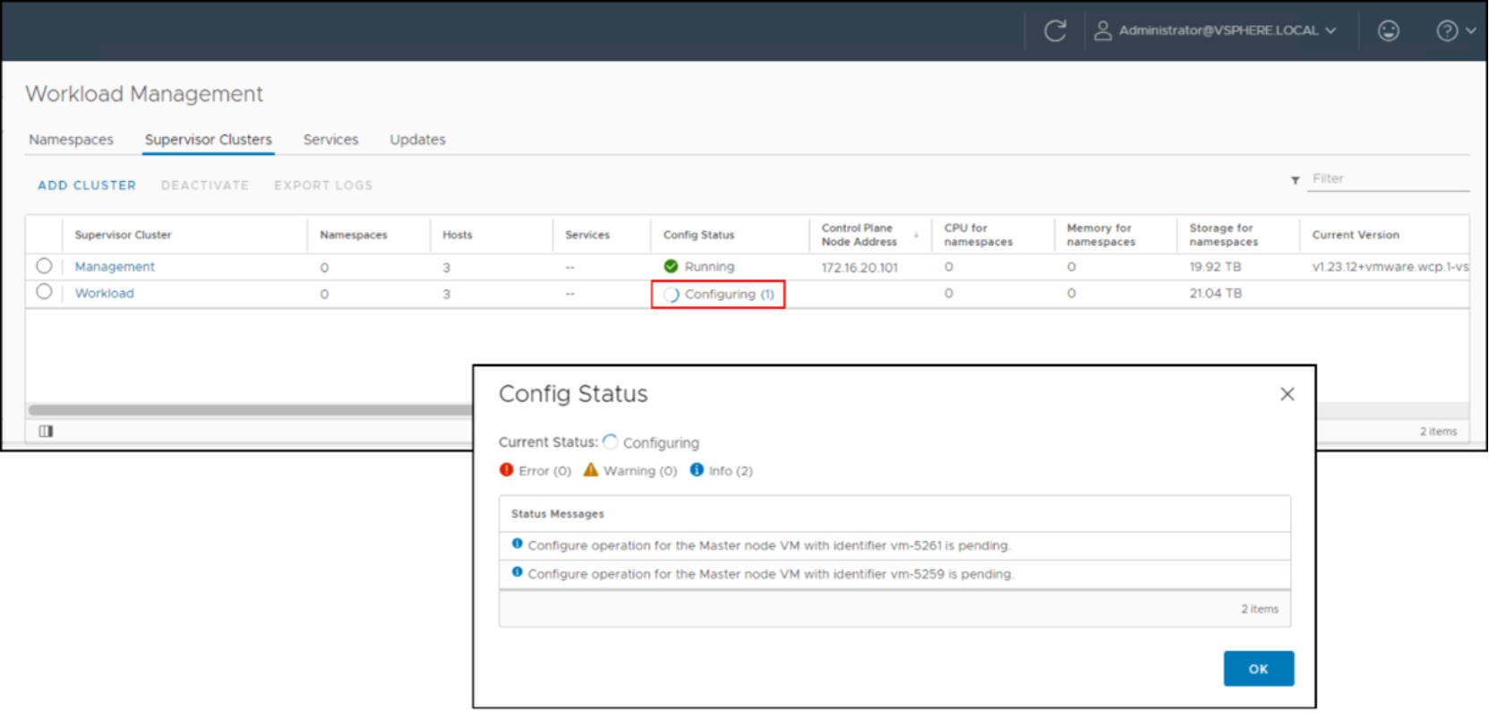
Figure 68. Workload Management – Config Status
The implementation of the Supervisor Cluster can take some time to complete. The Config Status changes to Running when it is done.
Namespace
After creating the Supervisor Cluster, you can create a namespace to manage resources. VMware creates this namespace on the Supervisor Cluster (for example, kubectl create namespace). The VMware namespace enables the administrator to control the resources of the Kubernetes cluster environment.
- In vSphere, go to the Workload cluster and the Namespace tab, as shown in Figure 69.
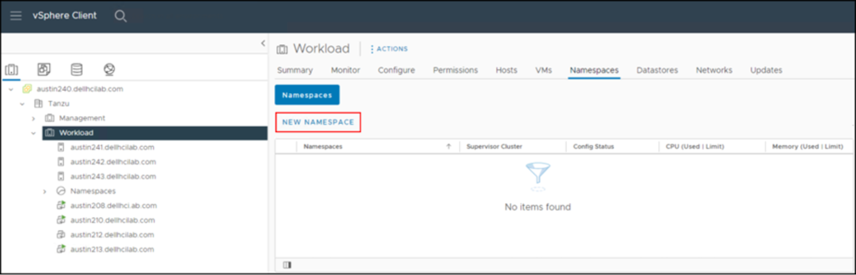
Figure 69. Create namespace – Step 1
- Click NEW NAMESPACE.
Note: This navigation path is one of many possible paths.
- Select the cluster where the namespace should be created. Despite highlighting the cluster, VMware does not default to it. You must select it.
- Enter a Name (required) and a Description (optional) for the namespace.
- Use the drop-down box next to Network to select the appropriate option.
In this example, there is only a single network. If there are multiple workload networks in ALB, they are available as options. See Figure 70.
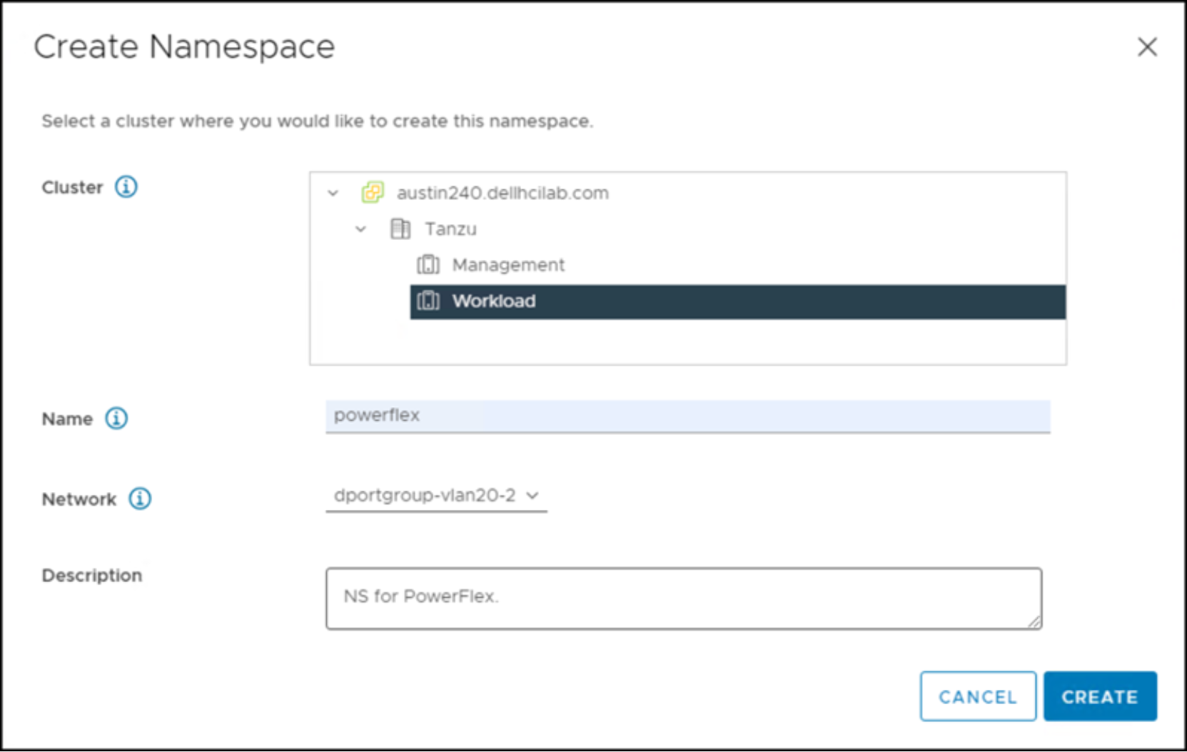
Figure 70. Create namespace – Step 2
The new namespace is immediately available. There are six different sections:
- Status
- Permissions
- Storage
- Capacity and Usage
- Tanzu Kubernetes Grid Service
- VM Service
You can modify many of these categories. Some are covered below.
Note: In the Tanzu Kubernetes Grid Service box, the Content Library is already defined, inheriting the value from the Supervisor Cluster.
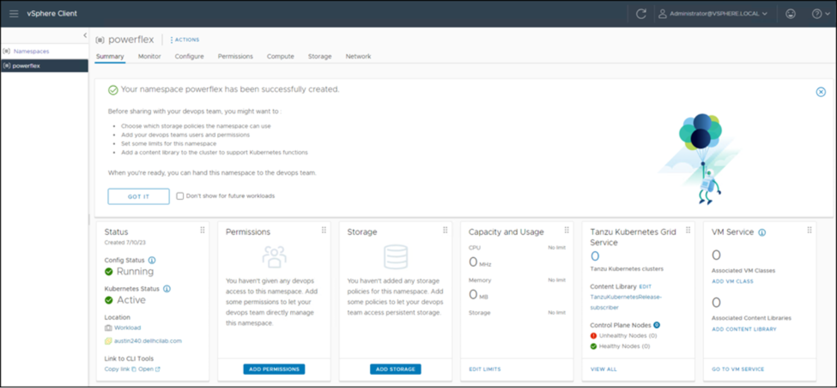
Figure 71. PowerFlex namespace
Permissions
- Provide access to the namespace by clicking ADD PERMISSIONS as shown in Figure 71 above. The Add Permissions dialog appears.
- Grant users or groups permissions to view, edit, or ownership to the namespace.
For example, if a user wants to grant view access to k8 developers from the local domain, the input appears like that shown in Figure 72.
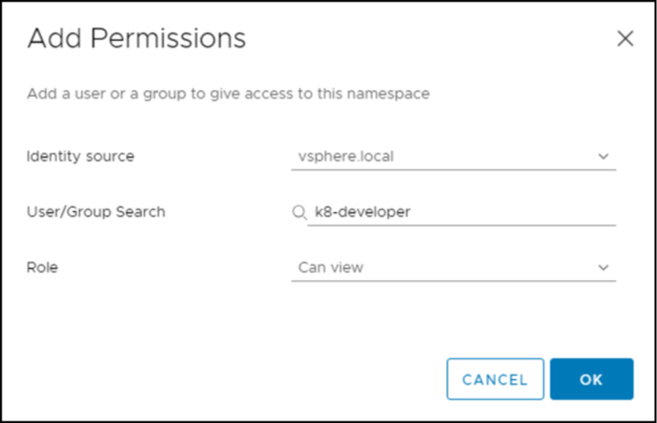
Figure 72. Namespace permissions
- Add all necessary permissions for the namespace before continuing.
Storage
Storage was tagged for the namespaces in the section Namespace tags.
- Provide storage policies for the namespace by clicking ADD STORAGE in the PowerFlex Namespace window (Figure 71 above). The Add Storage dialog appears.
- Select the previously created storage policies - Namespace-TCP, and Namespace-SCSI - in Figure 73.
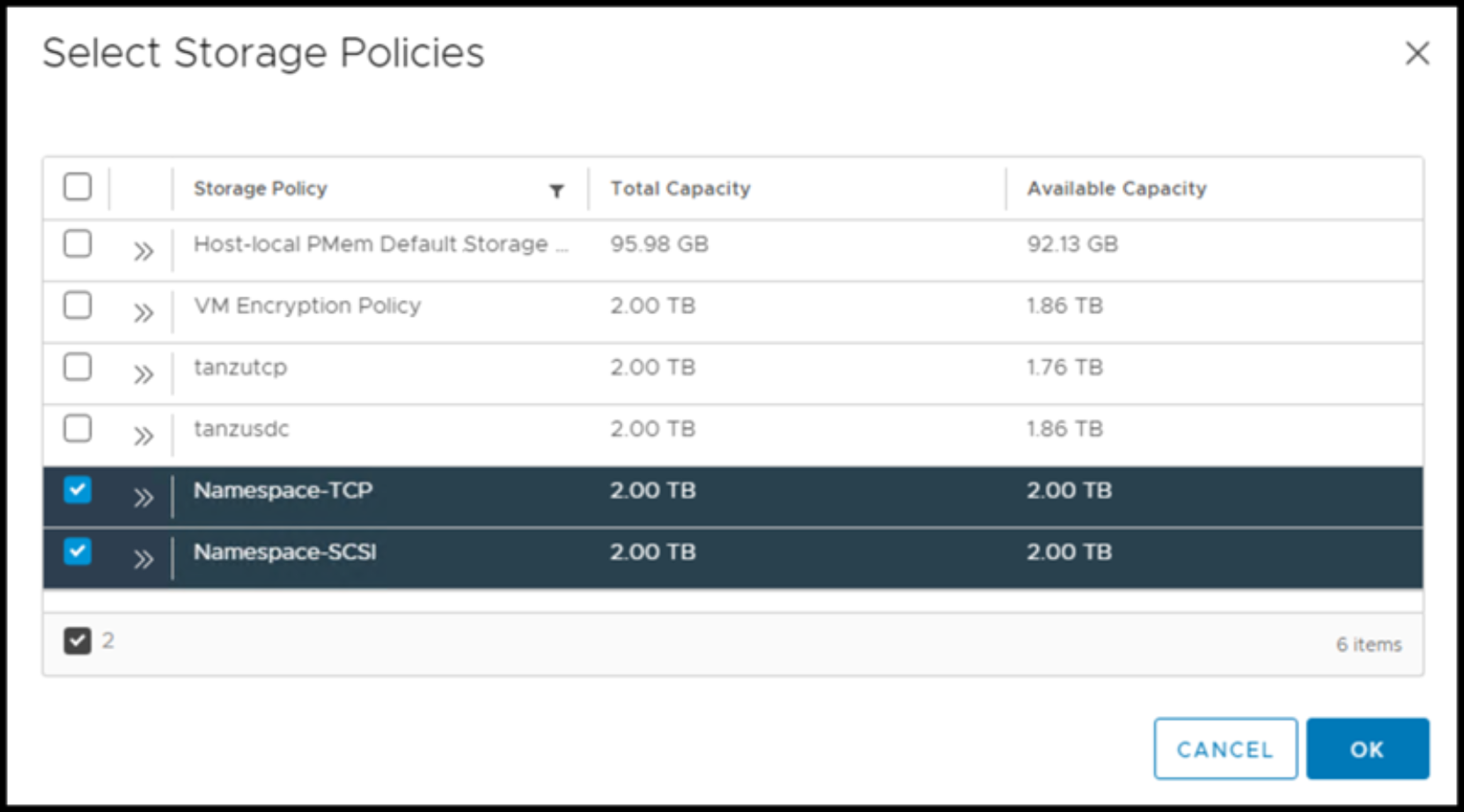
Figure 73. Namespace storage – storage policies
These storage policies are converted to Kubernetes storage classes in the Supervisor Cluster. If you want to give Kubernetes access to any other storage presented to the vCenter, it should be assigned here. Storage policies are the only way to do this access.
- Create any additional storage policies which map to that storage and assign them here. VMware creates the storage classes.
The two storage policies in Figure 73 can be seen during Kubernetes cluster creation.
Capacity and usage
- Provide access to the namespace by clicking EDIT Limits in the Capacity and Usage box in the PowerFlex Namespace window (Figure 71 above).
- Optionally, enter the limitations that you want for CPU, Memory, and Storage. See Figure 74.
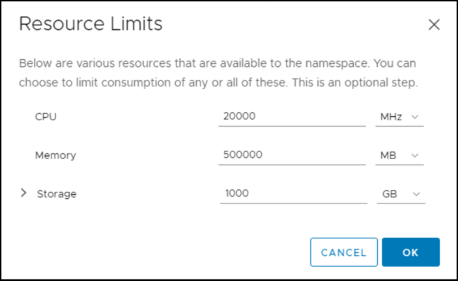
Figure 74. Namespace capacity and usage – Edit limits
VM Service
Finally, you must add some VM Classes which are used when creating Kubernetes clusters in the namespace. This step is mandatory.
- Click ADD VM CLASS in the PowerFlex Namespace window (Figure 71 above) to display the Manage VM Classes window, as shown in Figure 75.
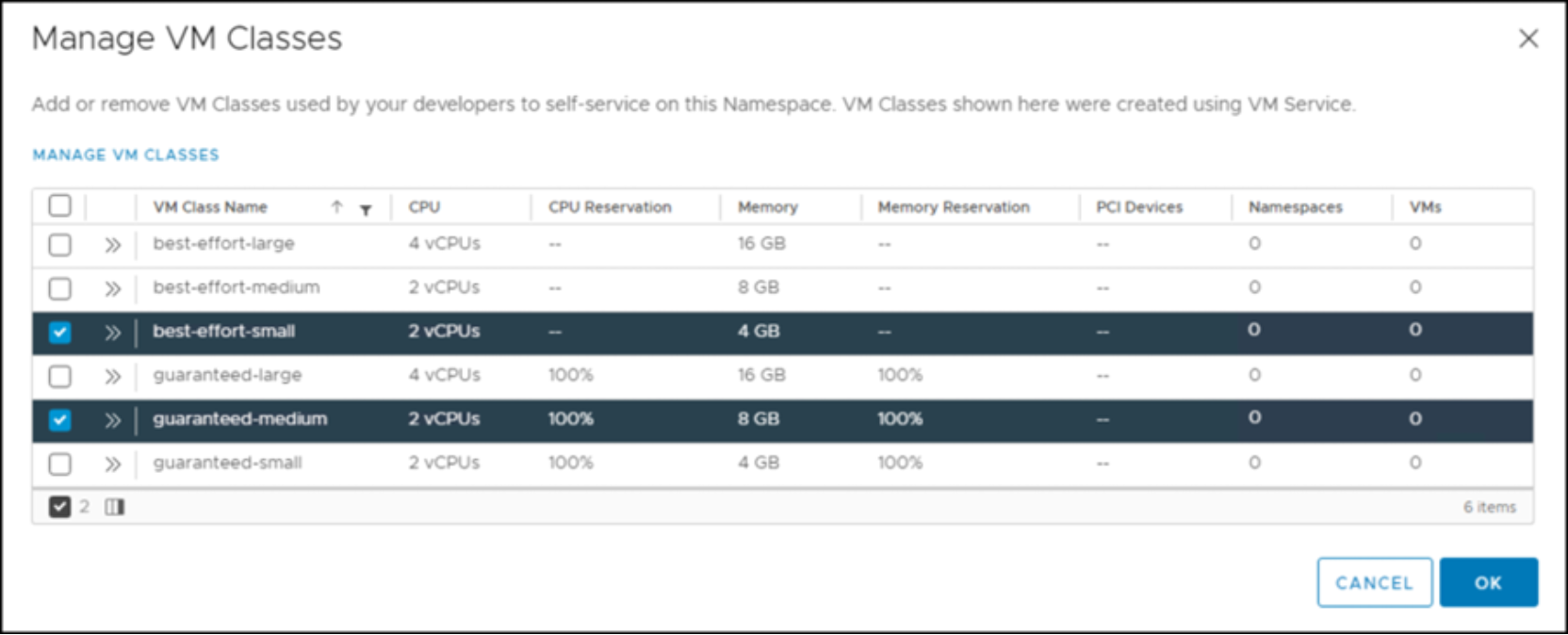
Figure 75. Manage VM Classes
- Use the checkboxes to select which VMs Classes or templates to assign to the namespaces.
Note: When building a YAML file for a Kubernetes cluster, the class parameter refers to one of these classes to create the VMs.
- Review the Modifications as shown in Figure 76.
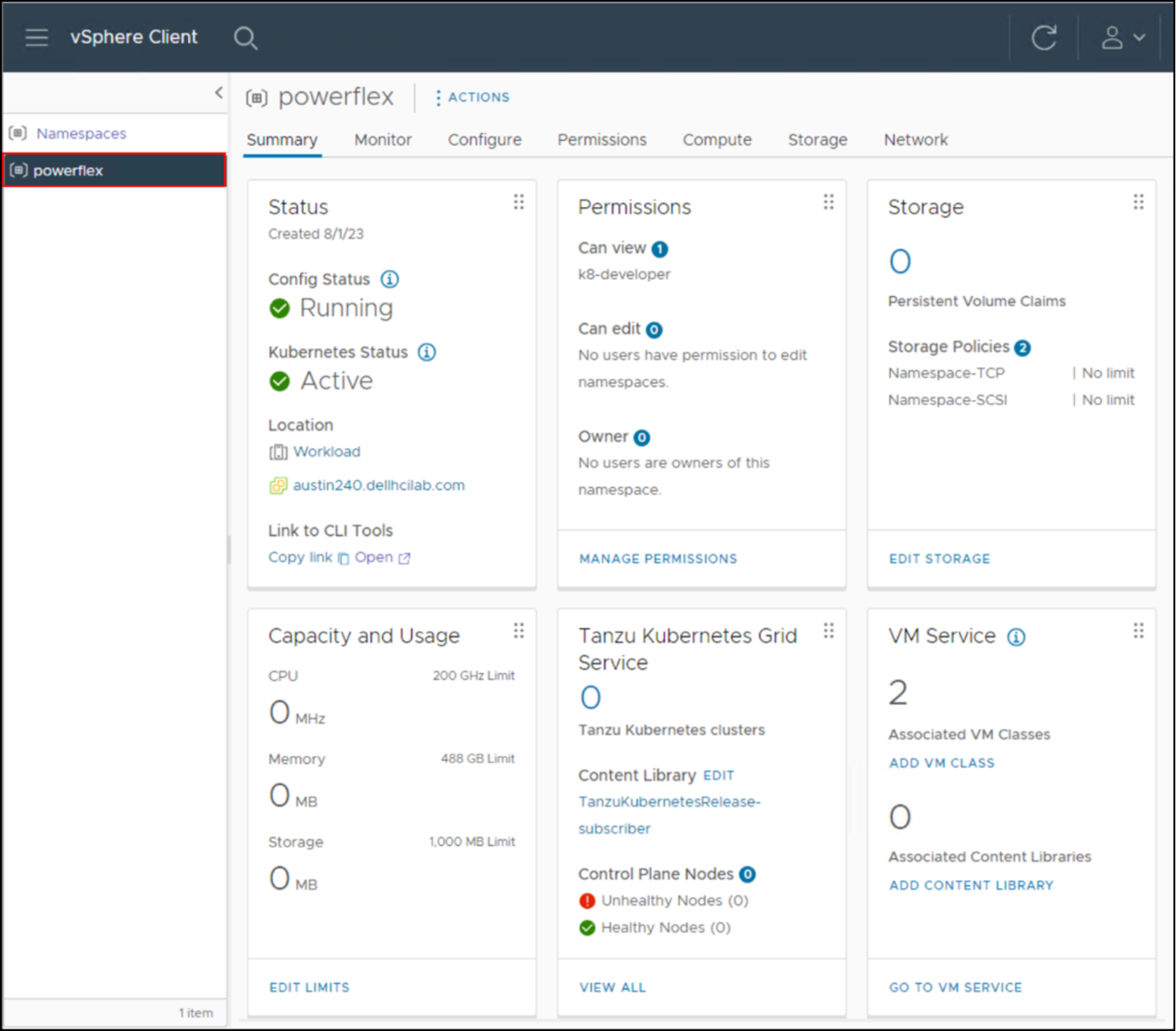
Figure 76. Completed PowerFlex namespace
CLI tools
The CLI tools enable a privileged user to create a Kubernetes cluster.
- Now that the namespace exists, download the CLI Tools from the Status box as shown in Figure 76 above.
- Click the Open hyperlink at the bottom of the Status box.
The Open hyperlink is pulled from the Control Plane Node Address of the Supervisor Cluster where the namespace was created, as shown in Figure 77.
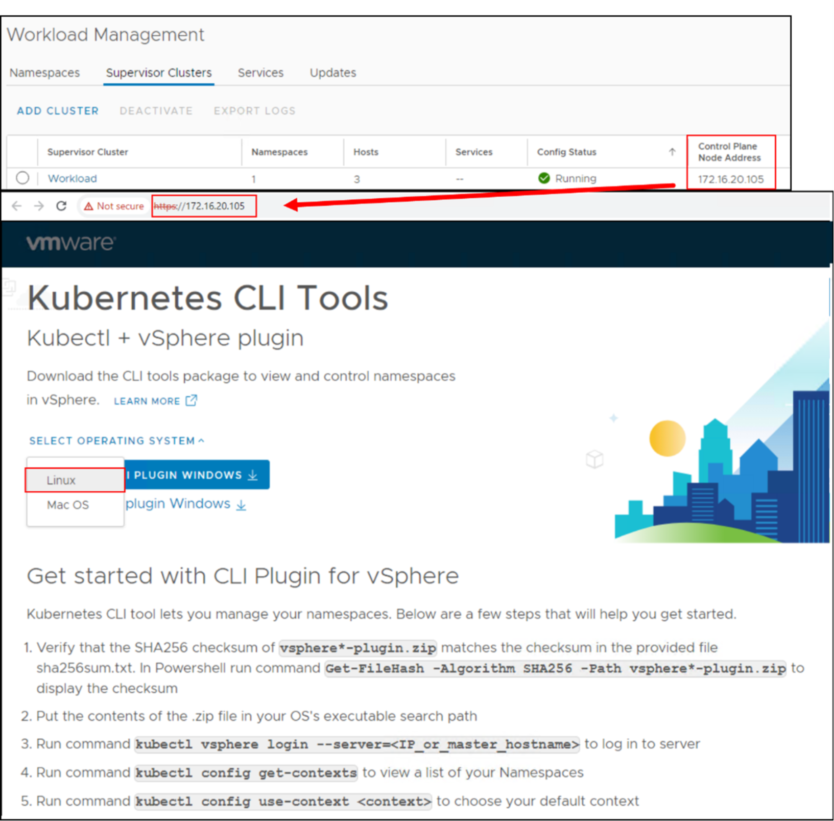
Figure 77. CLI Tools
The .zip file contains two binaries which can be copied into the proper operating system (for example, Linux) of a machine configured for the purpose. Utilizing these binaries, users who have been given permission to the namespace can access the environment.
Figure 77 above displays the steps for logging in to the namespace.
- Log in to the Linux host where the user copied the binaries.
- Following Step 3 as shown in Figure 77, login to the namespace. The password can be set before running the command by setting the variable KUBECTL_VSPHERE_PASSWORD.
kubectl-vsphere login --server 172.16.20.105 -u \ administrator@vsphere.local
Kubernetes cluster creation
- Once connected, view the available contexts.
- Set the current context to the namespace previously created.
kubectl config get-contexts
kubectl config use-context powerflex
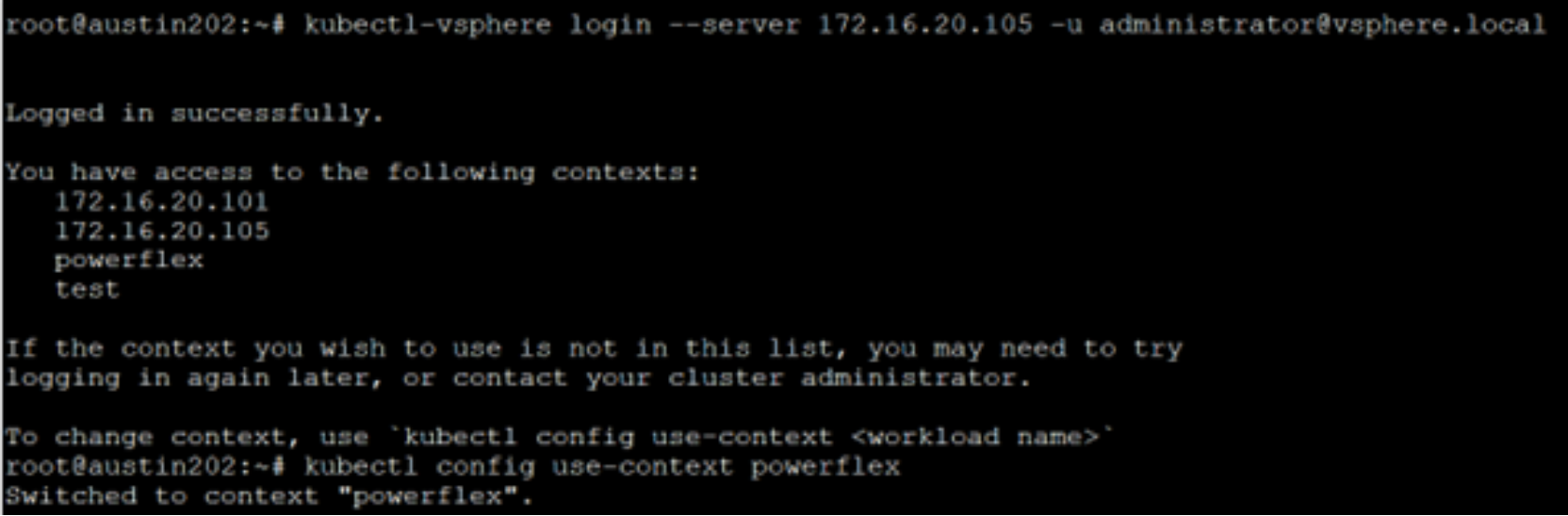
Figure 78. Logging in to a namespace and switching contexts
- Check the available VM templates or VM classes and the available Tanzu images. This environment includes the best effort small and guaranteed medium images.
kubectl get virtualmachineclassbindings
kubectl get tkr
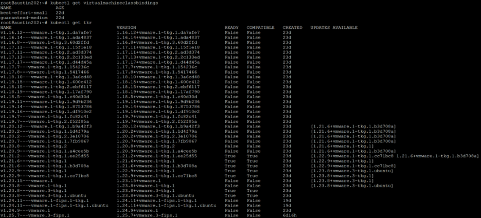
Figure 79. List VM classes and Kubernetes builds
The user also requires the available storage classes. This information is listed in the UI. However, because of the previously mentioned restrictions around storage class naming, the classes that are listed in the UI may differ than what Kubernetes uses. For example, capital letters are not permitted for storage classes. Therefore, the two storage classes that are listed in the UI - Namespace-SCSI and Namespace-TCP - are renamed to namespace-scsi and namespace-tcp in Kubernetes.
- Use the following command to pull the correct names for Kubernetes:
kubectl get sc
The user can use this information to create a Kubernetes cluster using TKGS in the powerflex namespace. There are two APIs available for creating the cluster: v1alpha1 API and v1alpha2 API.
VMware advises using v1alpha2 API since v1alpha1 API is deprecated. However, v1alpha2 API has some specific version requirements (for example, ESXi 7.0U3). If the environment does not meet them, use v1alpha1 API. The lab in this example meets the requirements, so the v1alpha2 API is used.
- Create a YAML file with the necessary components to create the cluster.
Note: The following YAML is a basic cluster configuration. The most important adjustable parameters are bolded. Be sure that both the vmClass and StorageClass values are ones available for the chosen namespace (previously queried above).
apiVersion: run.tanzu.vmware.com/v1alpha2
kind: TanzuKubernetesCluster
metadata:
name: pf-cluster
namespace: powerflex
spec:
topology:
controlPlane:
replicas: 1
vmClass: guaranteed-medium
storageClass: namespace-scsi
tkr:
reference:
name: v1.23.8---vmware.3-tkg.1
nodePools:
- name: worker-nodes
replicas: 3
vmClass: guaranteed-medium
storageClass: namespace-tcp
tkr:
reference:
name: v1.23.8---vmware.3-tkg.1
- Run the YAML file and then describe it, as shown in Figure 80.
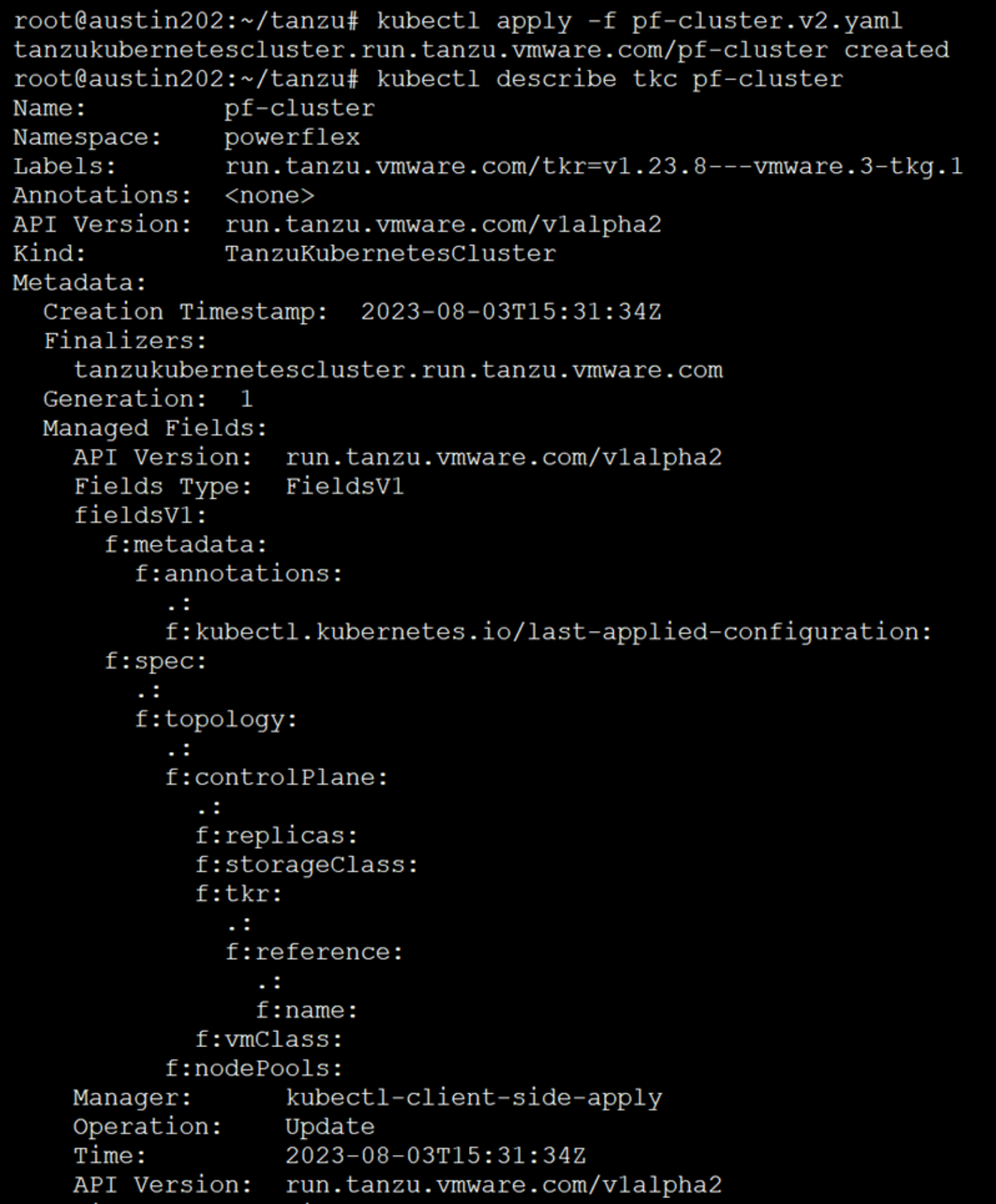
Figure 80. Creating a Tanzu Kubernetes cluster
The user can monitor the creation of the cluster from the namespace within vCenter.
- Under the Compute tab, view the VMware Resources – Tanzu Kubernetes cluster and Virtual Machines as shown in Figure 81.
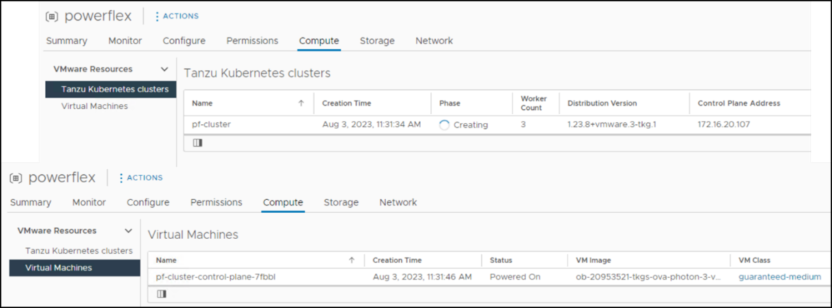
Figure 81. Monitoring cluster creation in the namespace
When cluster creation is complete, the Phase shows Running, as shown in Figure 82.
Note: As shown in the red box around the Control Plane Address, the load balancer provided the workload IP address.

Figure 82. Running Kubernetes cluster
- With the new cluster available, login to the namespace and cluster using the following command:
kubectl-vsphere login --server 172.16.20.105 -u \ administrator@vsphere.local --tanzu-kubernetes-cluster-namespace \ powerflex --tanzu-kubernetes-cluster-name pf-cluster
The output is shown in Figure 83.
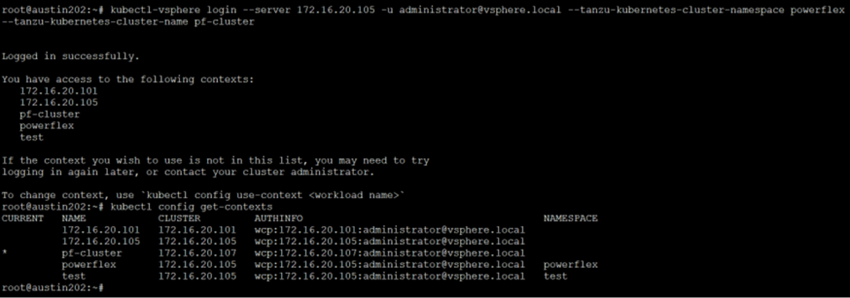
Figure 83. Log in to the new cluster
At this point, applications can be deployed on the new cluster. For completeness, an example is available in Appendix A, Application deployment.
Conclusion
Summary
We value your feedback
References
Dell Technologies documentation
VMware documentation
Kubernetes documentation
Application deployment
Introduction
Kustomize
Kustomize is a stand-alone tool that is part of Kubernetes and can be used to customize objects. It lets users manage objects like secrets and deployments in a single file. It is used here.
Prerequisites
There are three parts to the deployment:
- A secret generator
- A MySQL deployment
- A WordPress deployment
Secret generator
The secret generator is placed directly in the kustomization file. The bolded value should be adjusted for personal preference:
secretGenerator:
- name: mysql-pass
literals:
- password=oracle
The other two parts are referenced in the kustomization file as resources, but the YAML files must exist for them.
MySQL YAML
The bolded items require customization according to the user environment. Any referenced objects (like storage classes) must exist in the chosen namespace.
mysql-deployment.yaml
apiVersion: v1
kind: Service
metadata:
name: wordpress-mysql
labels:
app: wordpress
spec:
ports:
- port: 3306
selector:
app: wordpress
tier: mysql
clusterIP: None
---
apiVersion: v1
kind: PersistentVolumeClaim
metadata:
name: mysql-pv-claim
labels:
app: wordpress
spec:
storageClassName: namespace-tcp
accessModes:
- ReadWriteOnce
resources:
requests:
storage: 20Gi
---
apiVersion: apps/v1
kind: Deployment
metadata:
name: wordpress-mysql
labels:
app: wordpress
spec:
selector:
matchLabels:
app: wordpress
tier: mysql
strategy:
type: Recreate
template:
metadata:
labels:
app: wordpress
tier: mysql
spec:
containers:
- image: mysql:8.0
name: mysql
env:
- name: MYSQL_ROOT_PASSWORD
valueFrom:
secretKeyRef:
name: mysql-pass
key: password
- name: MYSQL_DATABASE
value: wordpress
- name: MYSQL_USER
value: wordpress
- name: MYSQL_PASSWORD
valueFrom:
secretKeyRef:
name: mysql-pass
key: password
ports:
- containerPort: 3306
name: mysql
volumeMounts:
- name: mysql-persistent-storage
mountPath: /var/lib/mysql
volumes:
- name: mysql-persistent-storage
persistentVolumeClaim:
claimName: mysql-pv-claim
WordPress YAML
The bolded items require customization according to the user environment. Any referenced objects (like storage classes) must exist in the chosen namespace.
wordpress-deployment.yaml
apiVersion: v1
kind: Service
metadata:
name: wordpress
labels:
app: wordpress
spec:
ports:
- port: 80
selector:
app: wordpress
tier: frontend
type: LoadBalancer
---
apiVersion: v1
kind: PersistentVolumeClaim
metadata:
name: wp-pv-claim
labels:
app: wordpress
spec:
storageClassName: namespace-tcp
accessModes:
- ReadWriteOnce
resources:
requests:
storage: 20Gi
---
apiVersion: apps/v1
kind: Deployment
metadata:
name: wordpress
labels:
app: wordpress
spec:
selector:
matchLabels:
app: wordpress
tier: frontend
strategy:
type: Recreate
template:
metadata:
labels:
app: wordpress
tier: frontend
spec:
containers:
- image: wordpress:6.2.1-apache
name: wordpress
env:
- name: WORDPRESS_DB_HOST
value: wordpress-mysql
- name: WORDPRESS_DB_PASSWORD
valueFrom:
secretKeyRef:
name: mysql-pass
key: password
- name: WORDPRESS_DB_USER
value: wordpress
ports:
- containerPort: 80
name: wordpress
volumeMounts:
- name: wordpress-persistent-storage
mountPath: /var/www/html
volumes:
- name: wordpress-persistent-storage
persistentVolumeClaim:
claimName: wp-pv-claim
Now create the kustomization file to create the secret generator then execute the two YAMLs.
secretGenerator:
- name: mysql-pass
literals:
- password=oracle
resources:
- mysql-deployment.yaml
- wordpress-deployment.yaml
Procedure
- Log in to the pf-cluster, apply the file, and view the various objects as shown in Figure 84.
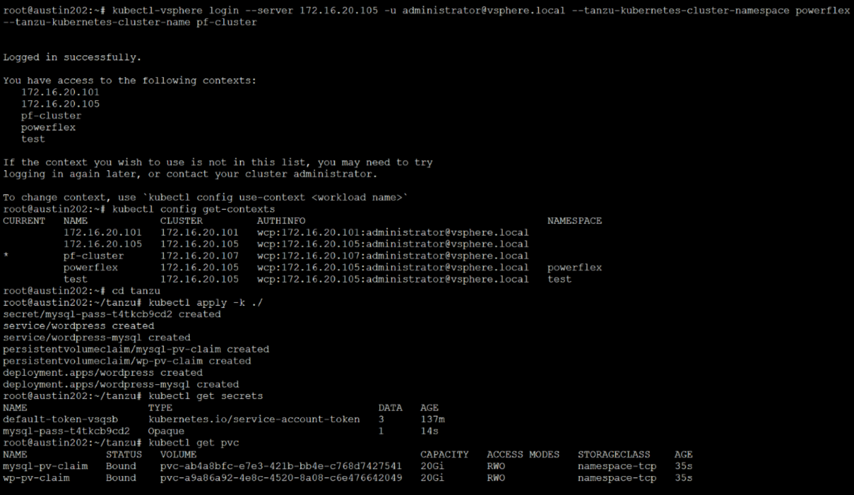
Figure 84. Kustomize application
- View the resources of the namespace in vCenter. Note the two new persistent volume claims, as shown in Figure 85.
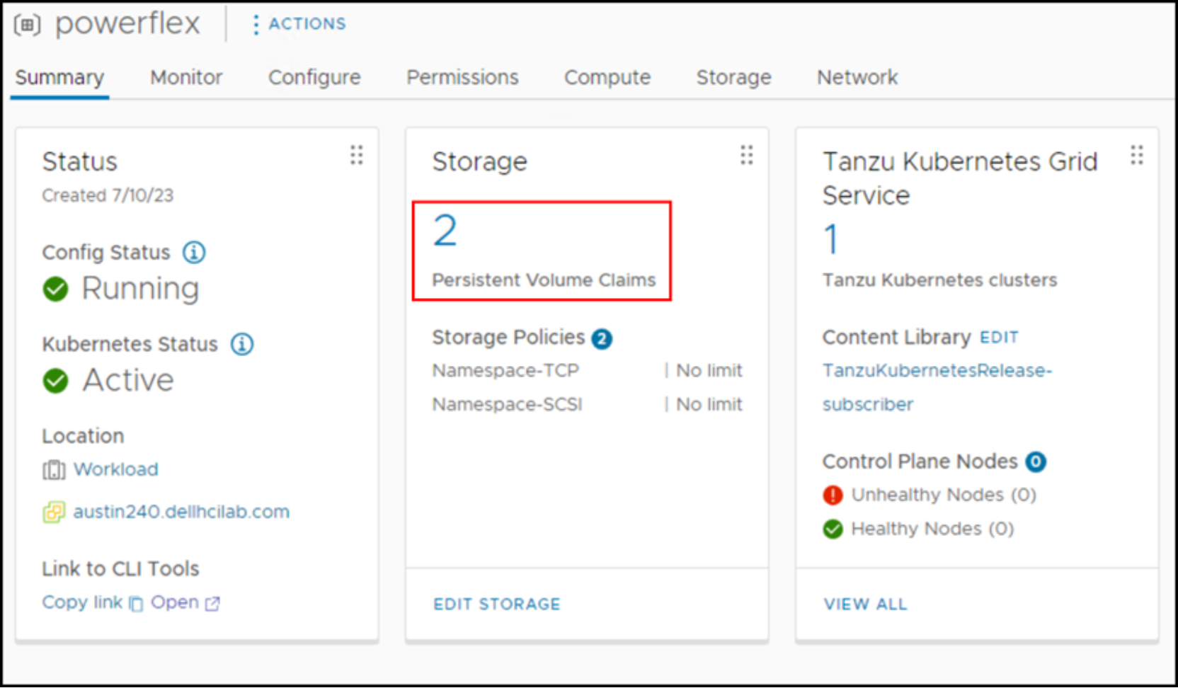
Figure 85. Persistent Volume Claims
- Click the hyperlink to get details about the volumes as seen in Figure 86.

Figure 86. PVC details
- Retrieve the ALB VIP that is associated with the WordPress application in Figure 87. This VIP is for the workload network and is accessible externally.

Figure 87. ALB VIP of WordPress
This IP address and port can be used to access the application through a browser. The EXTERNAL-IP uses port 80 as seen in Figure 88.
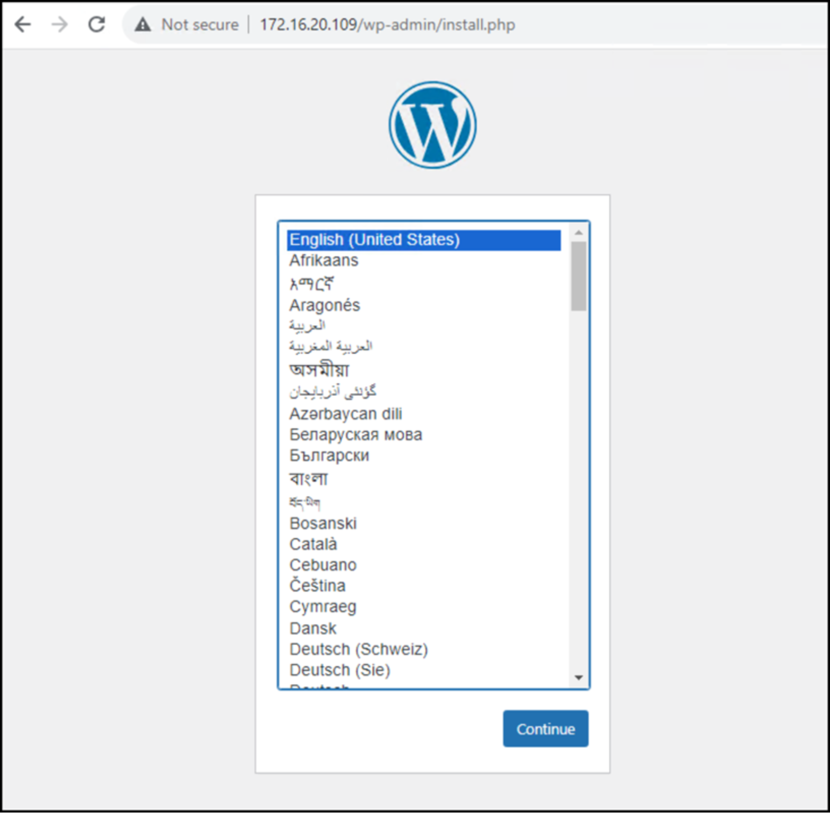
Figure 88. WordPress wizard
- Click Continue to go through and complete the wizard.
The install is complete as shown in Figure 89.
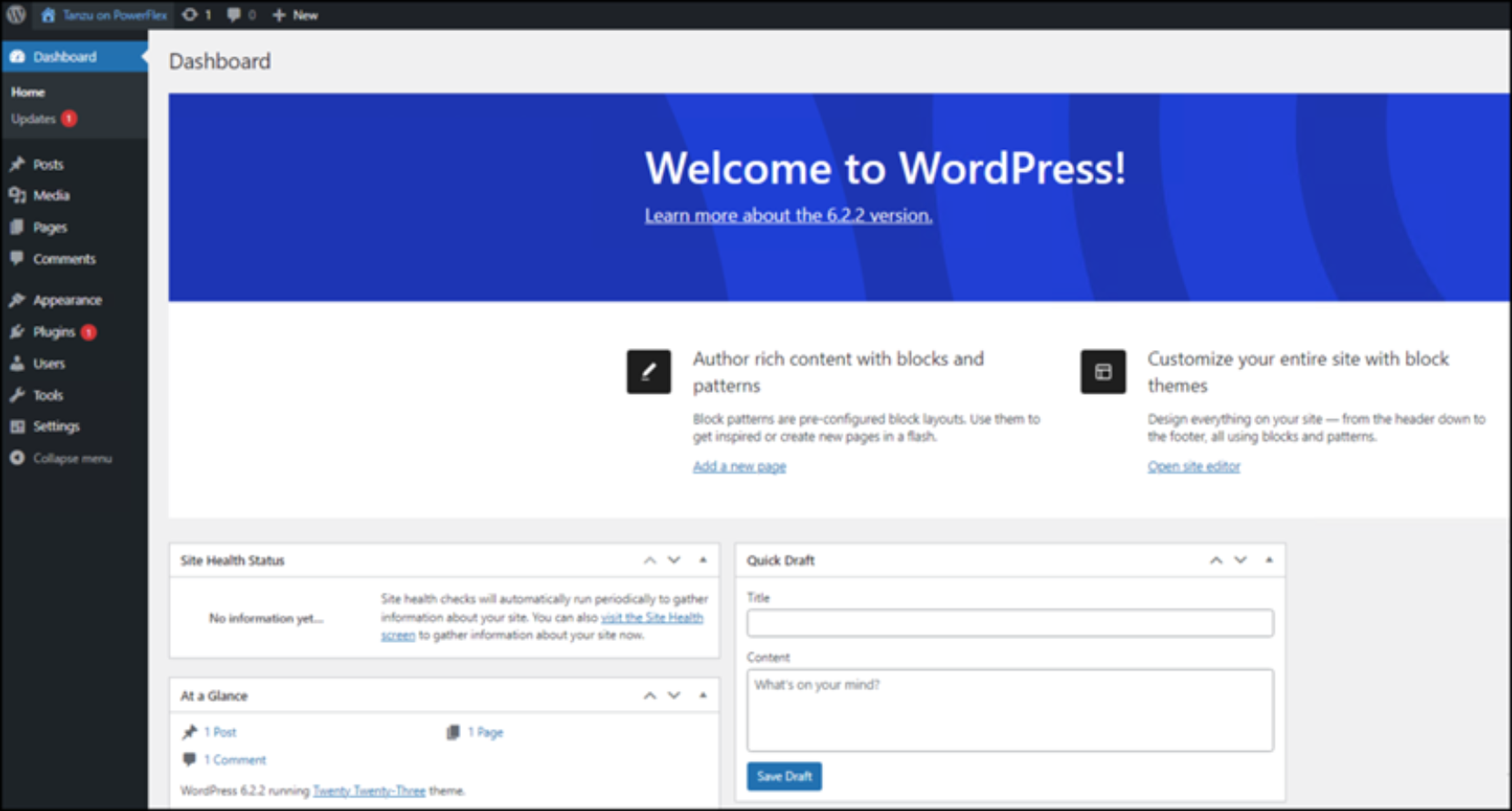
Figure 89. WordPress completed application