Implementing Red Hat OpenShift Container Platform on Dell PowerMax
Executive summary
Overview
Document purpose
Wizard walkthroughs
Audience
Terminology
Revisions
We value your feedback
Product overview
PowerMax
Unisphere for PowerMax
Solutions Enabler
Red Hat OpenShift Container Platform
Red Hat OpenShift Container Platform is an enterprise Kubernetes distribution that provides a consistent platform for deploying, managing, and scaling containerized applications across bare metal, virtualized, on-premise, and cloud environments. It extends upstream Kubernetes with additional components and automation to simplify cluster operations, application lifecycle management, and security.
An OpenShift cluster consists of nodes, each running Red Hat Enterprise Linux CoreOS (RHCOS), a minimal and hardened operating system derived from Red Hat Enterprise Linux (RHEL). After initialization, each node uses the CRI-O container runtime to manage container images and execute workloads. The Kubelet agent registers the node with the control plane, reports node status, and handles workload scheduling instructions.
OpenShift configures and manages cluster networking, ingress routing, and load balancing. It includes integrated services for monitoring, logging, and automated upgrades, enabling administrators to maintain cluster health and performance with minimal manual intervention.
The platform provides an internal container image registry and access to a catalog of certified Red Hat and community operators and images, supporting a broad set of application services, including databases, runtimes, and developer tools. You can deploy applications using standard Kubernetes objects such as Deployments and StatefulSets, or managed with Operators, which encapsulate operational logic for installation, configuration, and lifecycle management.
OpenShift supports building and managing custom container images from existing images and source code using integrated build tools. You can store these images in internal, private, or public registries and deployed through automated pipelines or direct configuration.
Cluster architecture
An OpenShift cluster is composed of two main node types: control plane nodes and worker nodes.
- Control plane nodes host the core Kubernetes services that maintain cluster state and coordinate workloads. These include the API server, controller manager, scheduler, and etcd key-value store for persistent configuration data.
- Worker nodes run user applications and services in containers. The Kubelet, CRI-O runtime, and SDN components operate on each worker to manage containers, networking, and storage.
OpenShift adds infrastructure components such as the Ingress Controller, Cluster Network Operator, Machine Config Operator, and Authentication services, which integrate platform-level management and policy enforcement. These components ensure automated updates, configuration drift management, and consistent security posture across all nodes.
Figure 1 shows a basic representation of the three-node, bare-metal OCP cluster as deployed in this paper which uses the Dell PowerMax as persistent storage.
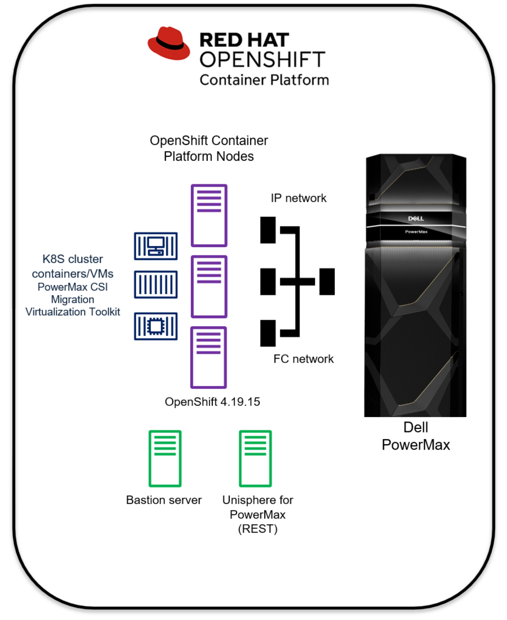
Figure 1. OpenShift Container Platform bare-metal cluster
Red Hat Hybrid Cloud Console
The Red Hat Hybrid Cloud Console is Red Hat’s web-based interface for managing OpenShift clusters across different infrastructures — including bare metal, on-prem, and cloud environments.
It provides centralized lifecycle management and visibility for clusters. Key functions are:
- Cluster creation and installation: Launch clusters using methods like the Assisted Installer, installer-provisioned infrastructure (IPI), or bring-your-own (UPI).
- Registration and inventory: View all clusters (connected or disconnected), their health, version, and status in one dashboard.
- Lifecycle operations: Handle updates, scaling, and configuration changes.
- Access management: Control cluster access through Red Hat organization and identity integrations.
- Insights integration: Displays alerts, recommendations, and security information pulled from Red Hat Insights.
- Subscription tracking: Shows OpenShift subscription usage, entitlements, and connected hosts.
The console is the control plane for monitoring, provisioning, and maintaining multiple OpenShift environments.
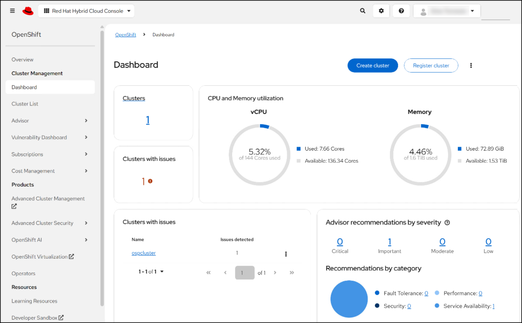
Figure 2. Red Hat Hybrid Cloud Console
OpenShift Web Console
The Red Hat OpenShift Web Console is a browser-based management platform for Kubernetes clusters. You access it from within the Hybrid Cloud Console for individual clusters. It provides administrators and developers with a centralized dashboard to monitor cluster health, manage workloads, configure networking, and deploy applications. The console includes navigation options such as Projects, Workloads, Operators, and Virtualization, enabling streamlined access to cluster resources and operational tools. Key features include guided documentation for cluster setup, integration with identity providers, and support for advanced capabilities like OpenShift Virtualization and AI-driven enhancements. This interface is essential for maintaining cluster stability, observing real-time status indicators, and performing administrative tasks through an intuitive graphical environment.
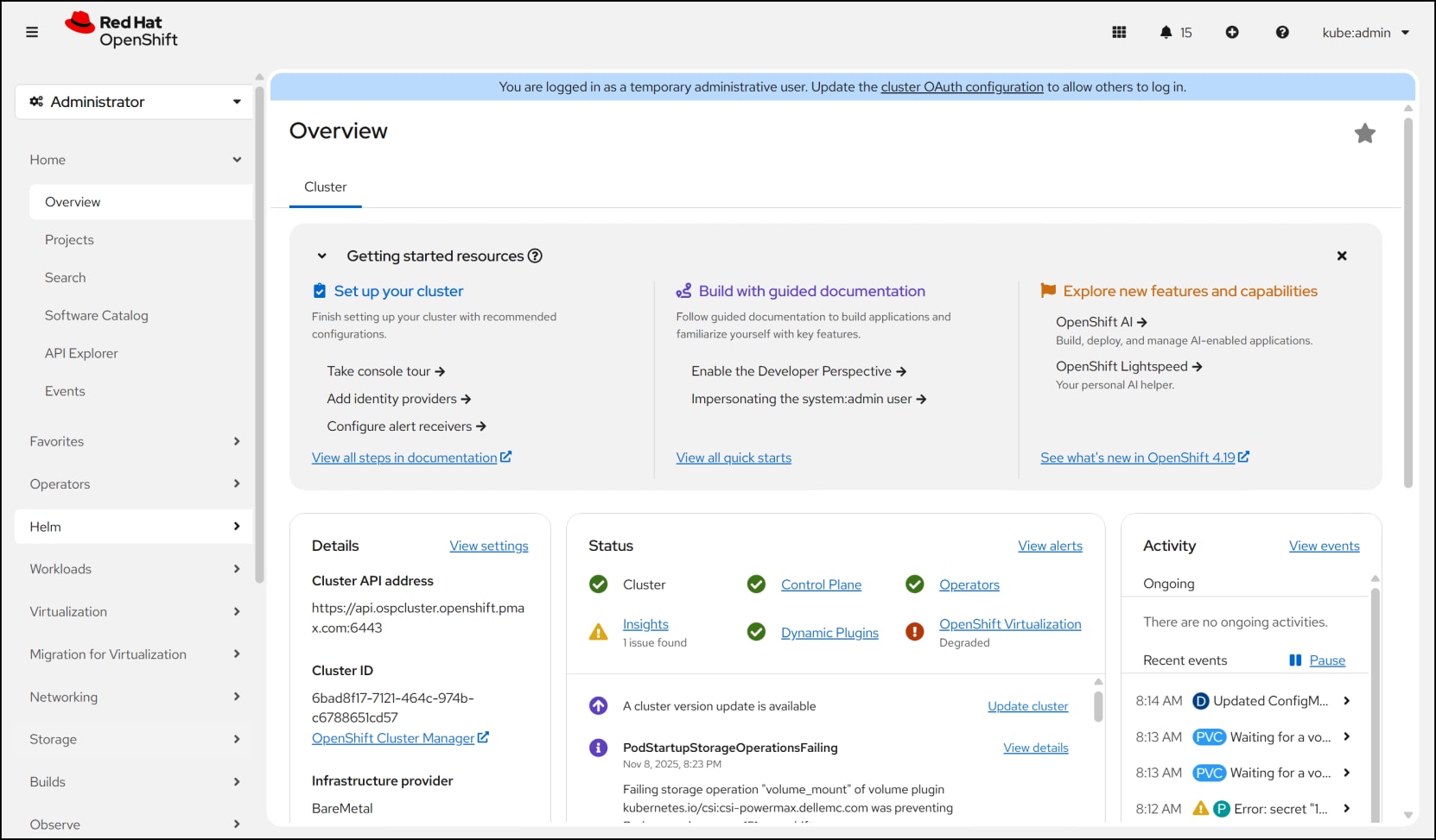
Figure 3. OpenShift Web Console
Environment and system requirements
Introduction
Prerequisites
OCP environment
The following is information about the specific environment detailed in this paper.
Cluster
This paper describes the deployment of a three-node, bare metal Red Hat OpenShift cluster running version 4.19.15. The update channel is stable-4.19.
Network topology
For the environment in this paper the following network exists. At the physical layer, there are two Top of Rack (TOR) switches used for redundancy and load-balancing purposes. There are two connections from each Dell host NIC used in the solution, one to TOR A and one to TOR B.
The following table lists the two VLANs configured for this solution.
Table 2. Network VLANs
|
Network type |
VLAN ID |
|
Management |
0 |
|
OCP |
105 |
FC connectivity
Each OCP host has two, two-port HBAs (32 Gb min) with connectivity to the PowerMax array. We zoned each HBA port to an FA port on the array so that a single HBA connects to two different directors as in Figure 4 (switches are implied). For larger arrays with more directors, spread connectivity over multiple engines.
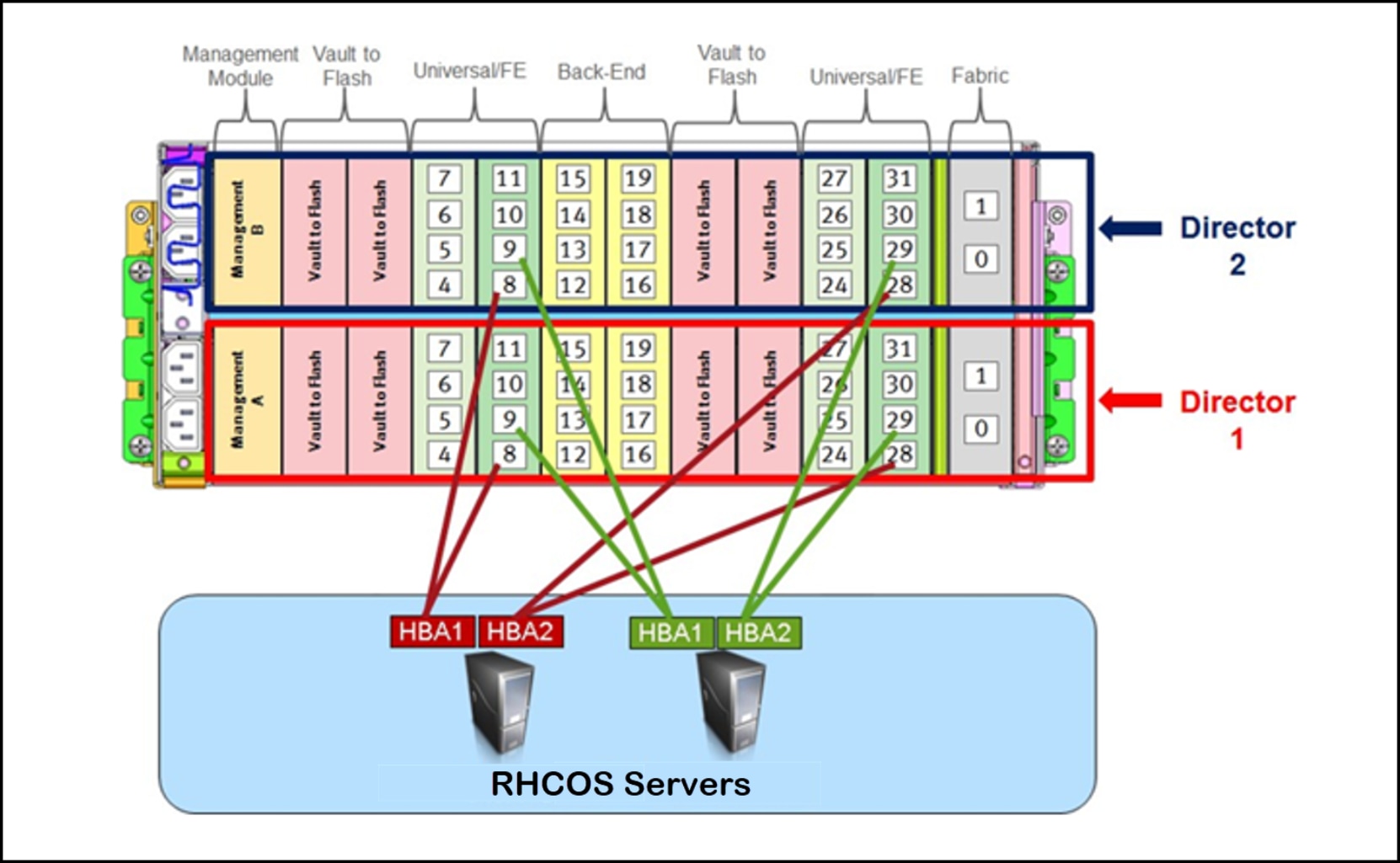
Figure 4. FC connectivity for a single engine PowerMax
OCP nodes
The OCP environment detailed in this paper consists of three servers in Table 3 which exceed the minimum requirements.
Table 3. OpenShift server configurations
|
System Component |
Node 1 |
Node 2 |
Node 3 |
|
Dell Model |
R740XD |
R740XD |
R740XD |
|
CPU |
2 × Intel Xeon Gold 6242 (2.8 GHz, 16 cores each) |
2 × Intel Xeon Gold 6242 (2.8 GHz, 16 cores each) |
2 × Intel Xeon Gold 6242 (2.8 GHz, 16 cores each) |
|
Memory |
512 GB (16 × 32 GB, 2933 MT/s NVDIMM-N DDR4) |
512 GB (16 × 32 GB, 2933 MT/s NVDIMM-N DDR4) |
512 GB (16 × 32 GB, 2933 MT/s NVDIMM-N DDR4) |
|
Storage |
2 × 447.13 GB SATA SSD |
2 × 447.13 GB SATA SSD |
2 × 447.13 GB SATA SSD |
|
Ethernet |
2 × Intel Ethernet 25 Gb 2-Port XXV710 Adapter |
2 × Intel Ethernet 25 Gb 2-Port XXV710 Adapter |
2 × Intel Ethernet 25 Gb 2-Port XXV710 Adapter |
|
Fibre Channel |
2 × Emulex LPe36002-M64-D 2-Port 64 Gb Fibre Channel Adapter |
2 × Emulex LPe36002-M64-D 2-Port 64 Gb Fibre Channel Adapter |
2 × Emulex LPe36002-M64-D 2-Port 64 Gb Fibre Channel Adapter |
Dell PowerMax storage
In an OpenShift cluster, array storage like Dell PowerMax provides persistent, high-performance, and reliable storage for VMs and containerized applications. Unlike ephemeral storage tied to individual nodes, array storage ensures data survives pod restarts, node failures, and scaling operations. It enables features like dynamic volume provisioning, persistent volumes, and storage classes, allowing applications to access shared storage efficiently. This is critical for stateful workloads such as databases, message queues, and enterprise applications that require consistent data availability and performance across the cluster.
Dell PowerMax arrays provide tiered performance through service levels, which you can map to storage classes. This allows you to assign the appropriate service level to each VM or container for optimal performance.
Service levels
A service level is a property of a storage group, a provisioning object on Dell PowerMax. The service level defines the maximum and minimum response times for I/O operations that involve the storage group. The minimum response time (known as the floor) defines the shortest time that each I/O operation on the storage group takes to complete. The maximum response time (known as the ceiling) defines the longest, acceptable time for any I/O operation on the storage group. PowerMax uses the floor and ceiling values to monitor whether each storage group complies with its quality-of-service criteria.
The storage administrator can use the service levels to help ensure that lower-priority applications do not impede storage groups associated with high-priority applications. The six service levels on the PowerMax are the following, beginning with the highest priority, and shown in Figure 5:
- Diamond
- Platinum
- Gold
- Silver
- Bronze
- Optimized
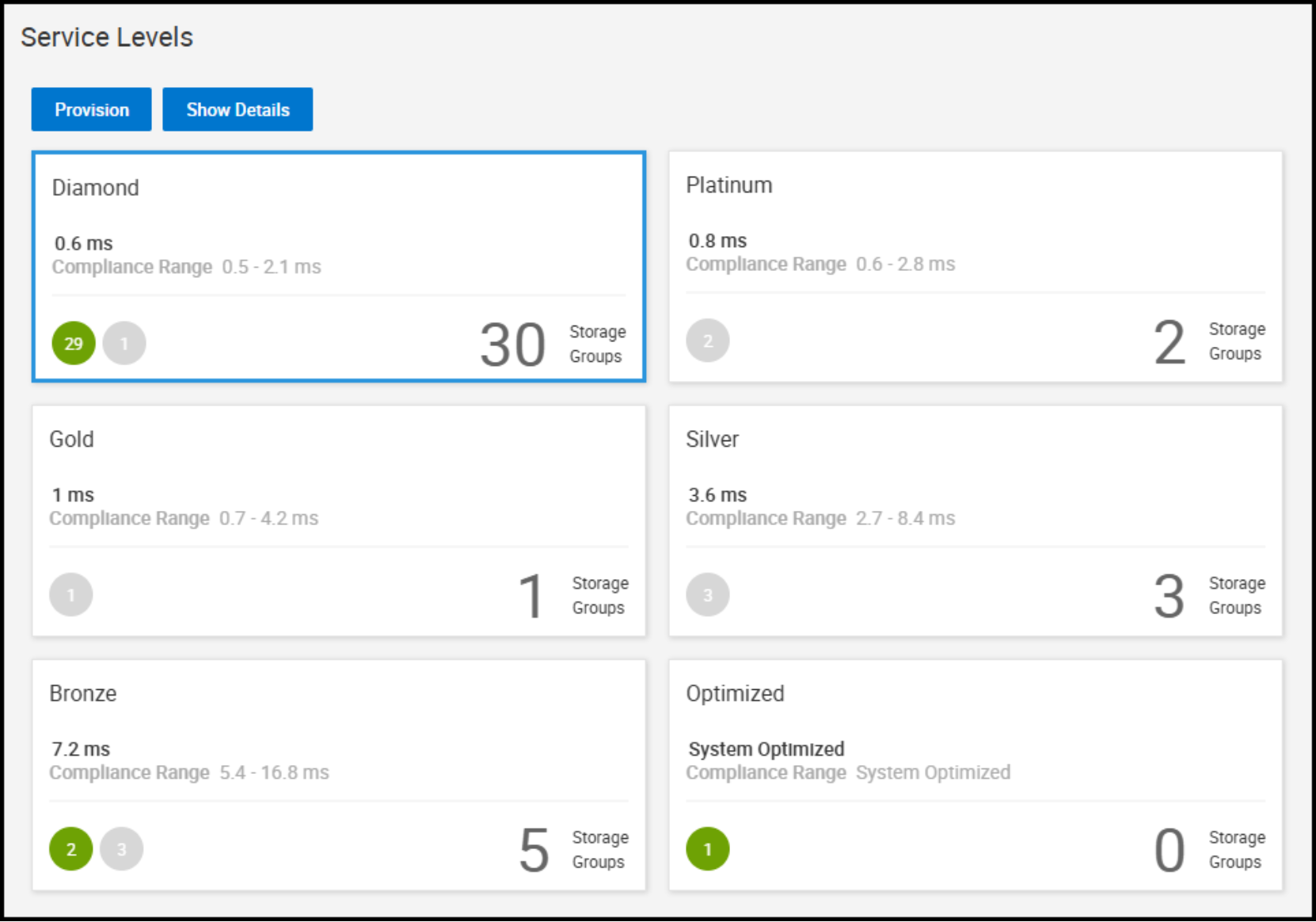
Figure 5. PowerMax service levels
Under normal operating conditions, PowerMax ensures that the performance is commensurate with the chosen service level’s compliance range. If, however, there is contention, PowerMax will prioritize higher service levels by limiting performance of the lower service levels. Therefore, it is essential to select the storage class best suited for the performance needs of the VM disk or containerized application.
OpenShift Cluster Installation
Assisted Installer
The Assisted Installer is one of the solutions available to install OCP. Red Hat offers it as SaaS through the Red Hat Hybrid Cloud Console, and it is the recommended methodology as it reduces the complexity inherent in some of the other solutions. The installer focuses on various solutions including bare metal, Oracle Cloud Infrastructure, vSphere, and Nutanix. In this paper’s on-premises implementation, the Installer supports the following different options:
- Highly available OpenShift Container Platform or single-node OpenShift cluster
- OpenShift Container Platform on bare metal or vSphere with full platform integration, or other virtualization platforms without integration
- OpenShift Virtualization and Red Hat OpenShift Data Foundation
Click Create cluster to start the process.
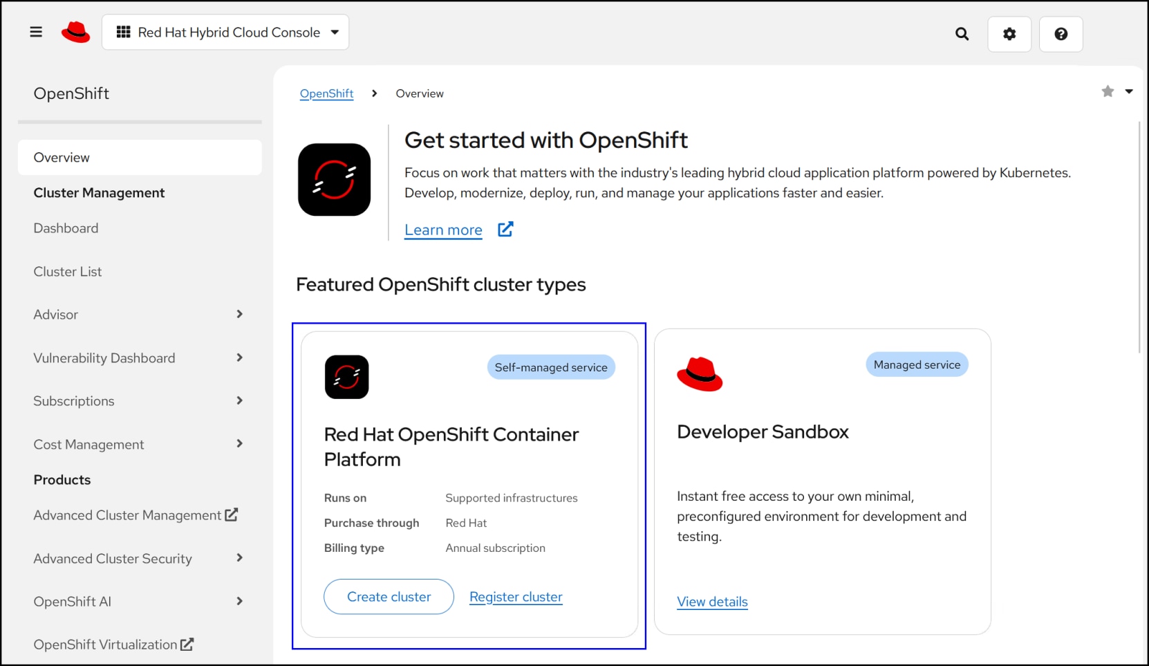
Figure 6. Creating a new cluster through Red Hat Hybrid Cloud Console
Navigate to the Datacenter tab and click on Create cluster again.
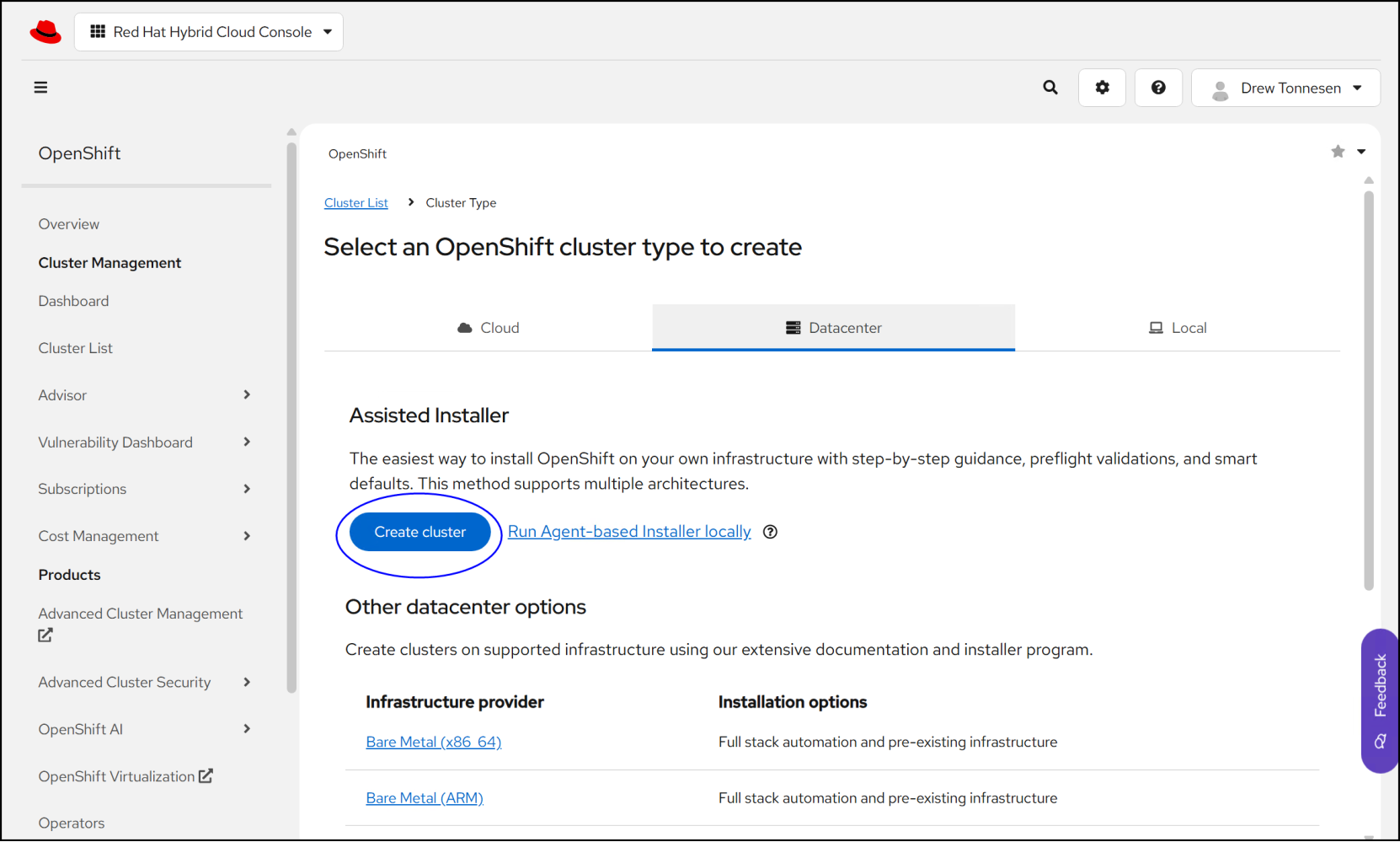
Figure 7. Datacenter create cluster
Note: The gray menu on the left-hand side in Figure 7 does not change throughout the Assisted Installer. Therefore, to enhance image quality, we removed them from the installation wizard images in this paper. We similarly removed the feedback and chat icons when required.
Step 1 Cluster details
In the first step, most of the values are default. Enter a Cluster name and Base domain (note the DNS entry requirement) and select the Hosts’ network configuration, DHCP or Static IP at the bottom of the screen. If you desire encryption, toggle one or more of the entries. The OpenShift version will always default to the most current version available. If necessary, adjust it to meet the support requirements of integrated components such as the PowerMax CSI driver. Click Next.
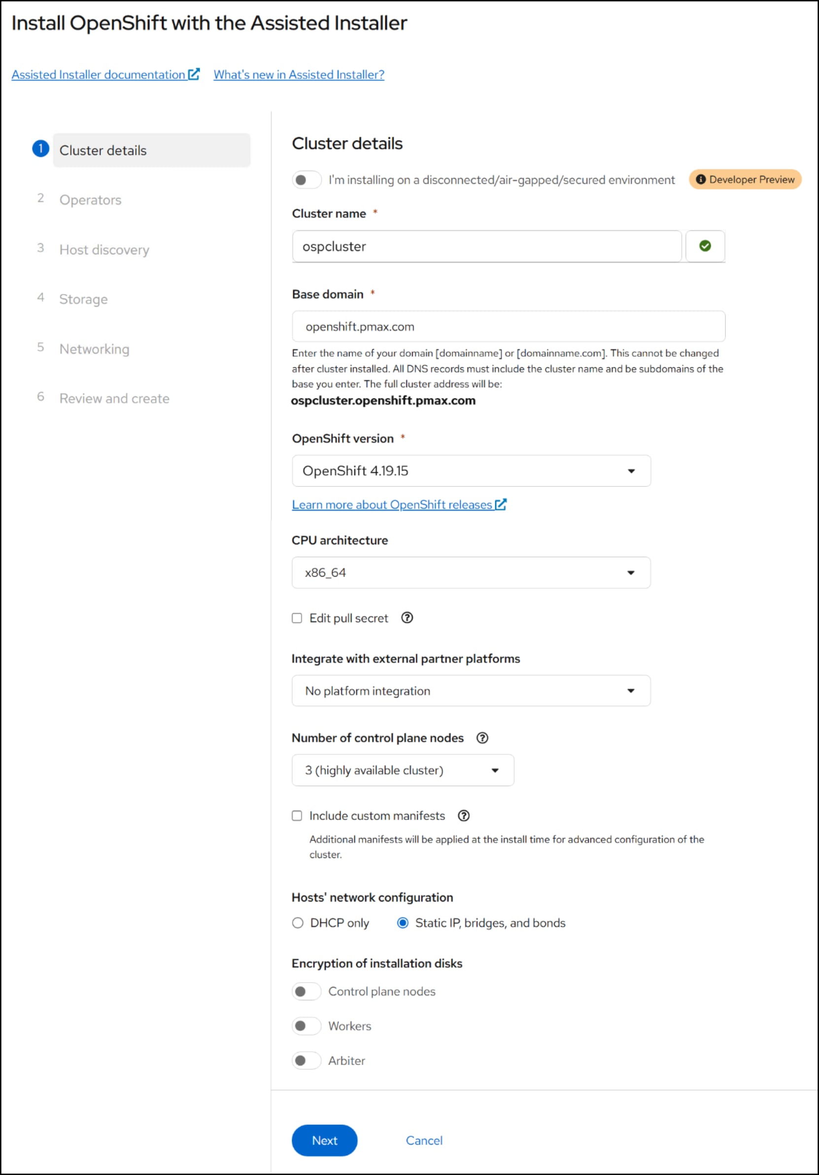
Figure 8. Step 1 – Cluster creation
Step 2a Static network configurations: Network-wide configurations
If you selected static IP in step 1, as in this wizard, step 2 covers both network-wide and host specific settings. If you selected DHCP, there is no network step at all, and the total steps reduce to six from seven.
For static IP, in the first screen the Configure via setting defaults to the Form view and is appropriate for most clusters. Choose the Networking stack type, a VLAN if desired, and the IP information. Click Next to move to host specific settings.
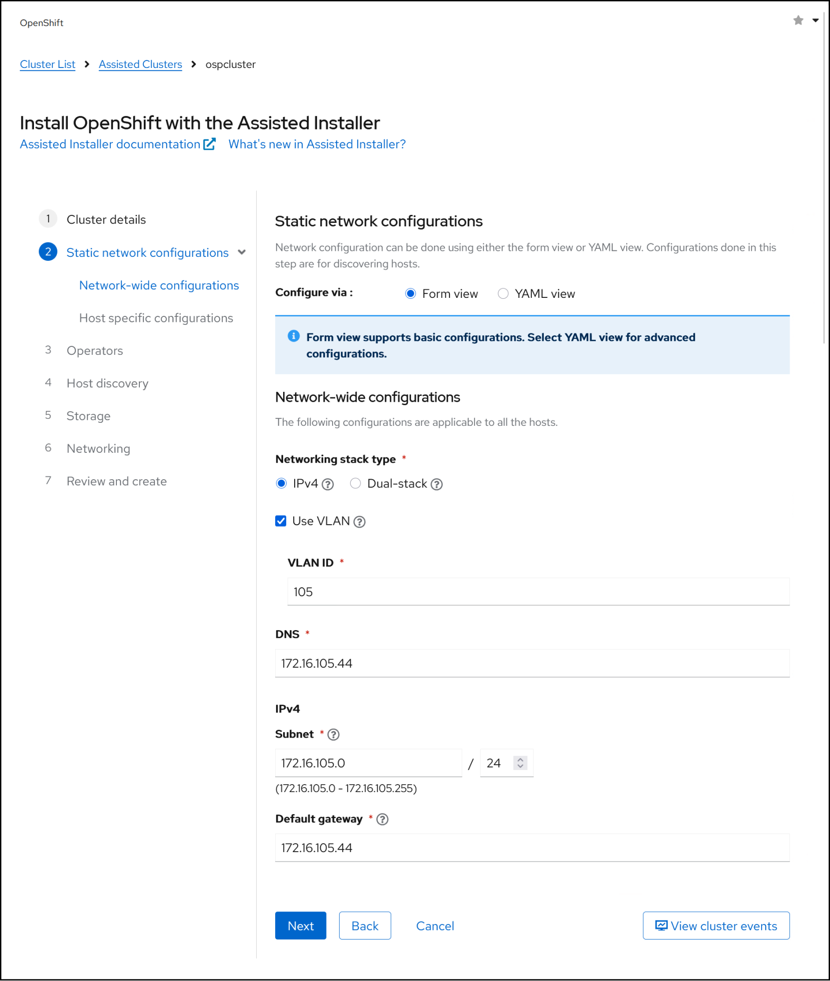
Figure 9. Step 2a – Cluster creation
Step 2b Static network configurations: Host specific configurations
The second part of step 2 requires that you obtain the MAC addresses of the NIC or NICs on the designated host. As these are Dell servers, we obtained the addresses using iDRAC. Below is an example of port one of the first NIC. This solution uses two NICs.
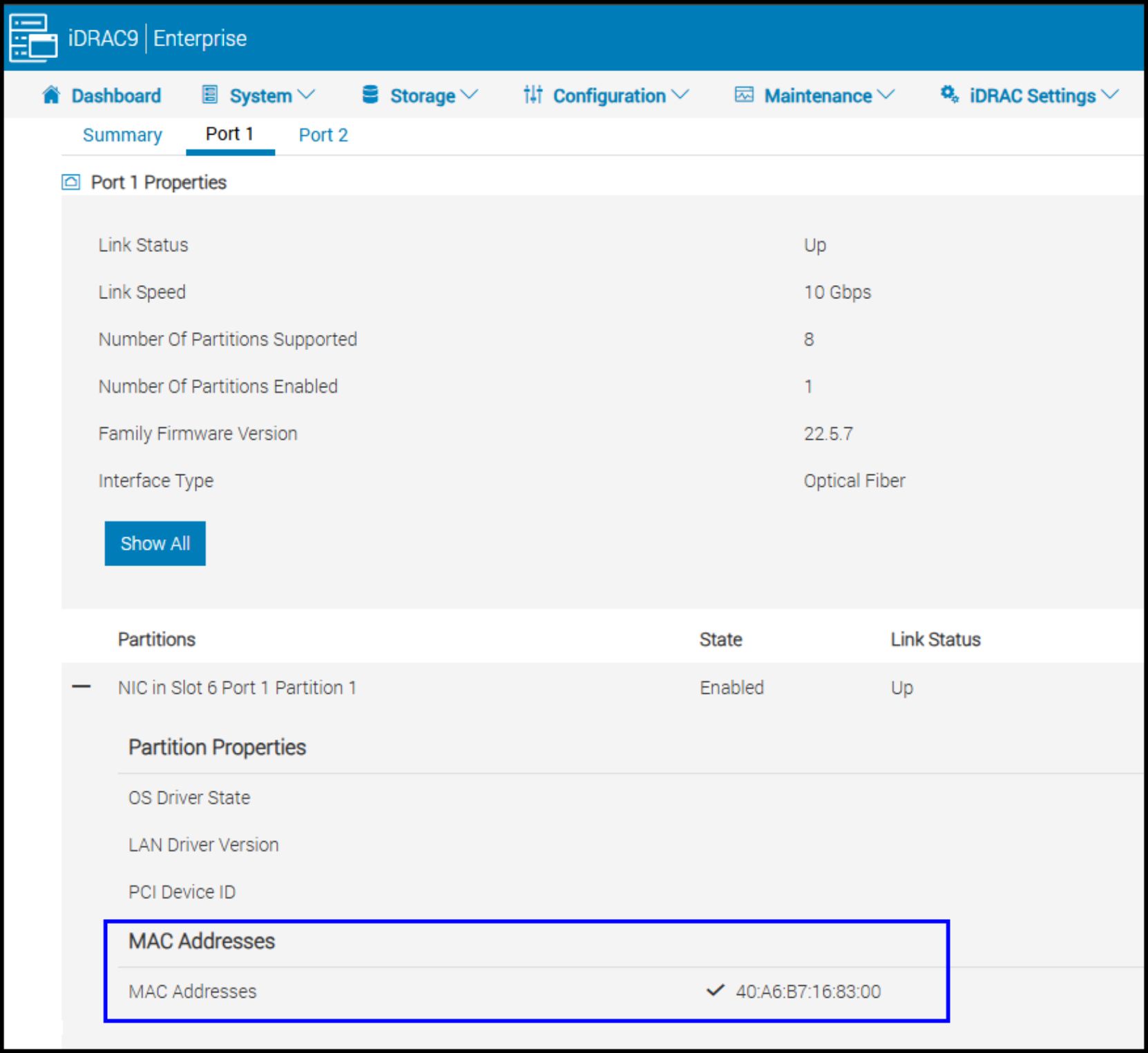
Figure 10. MAC address from iDRAC
Once you have the MAC address(es), enter the information into the wizard. As we are using two NIC ports, we check the Use bond box with the recommended Bond type of Active-Backup.
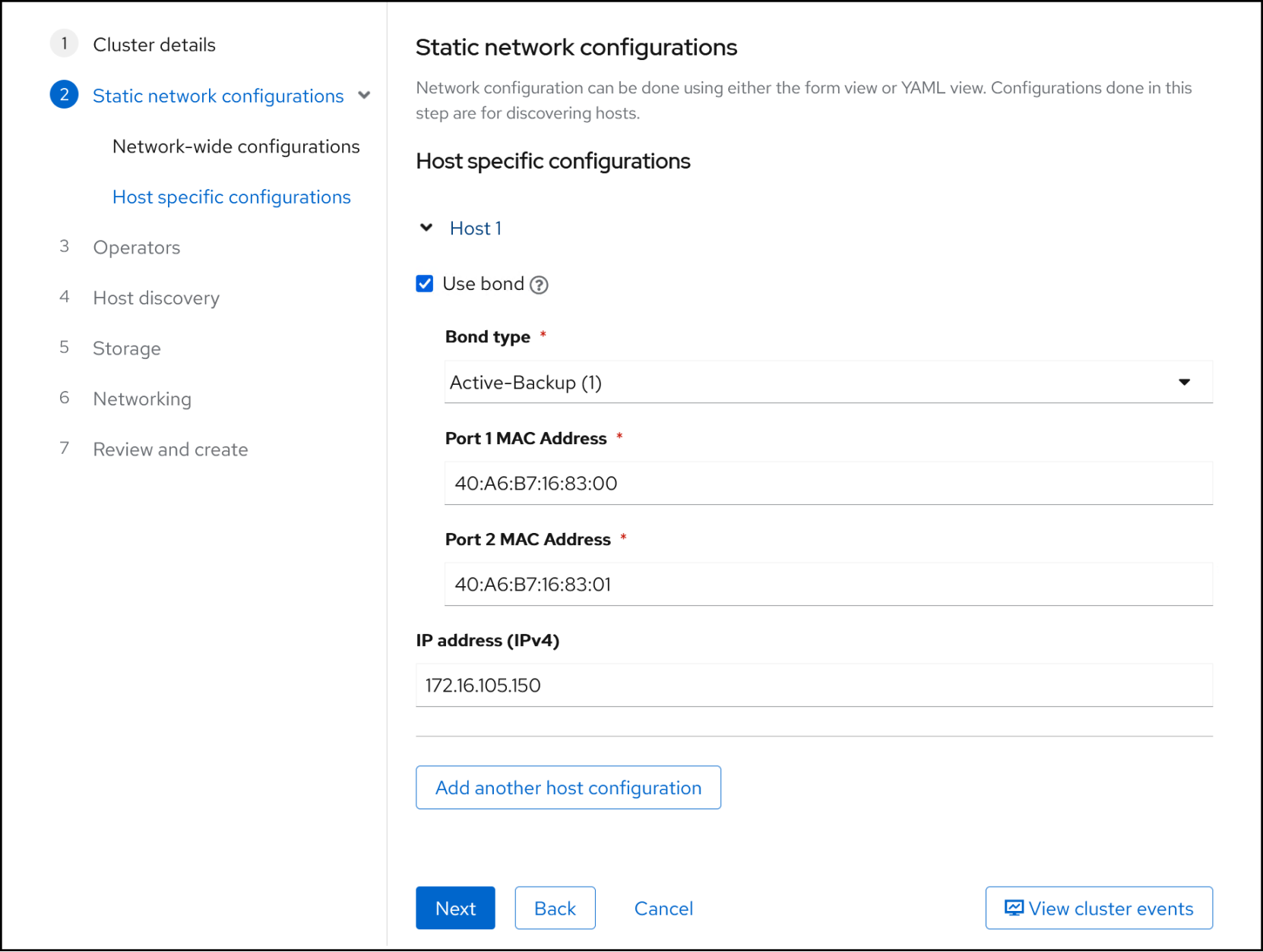
Figure 11. Step 2b – Cluster creation
As you add each host, the previous host(s) show at the top as in Figure 12. Complete the process for all three hosts, or however many hosts there are in your cluster.
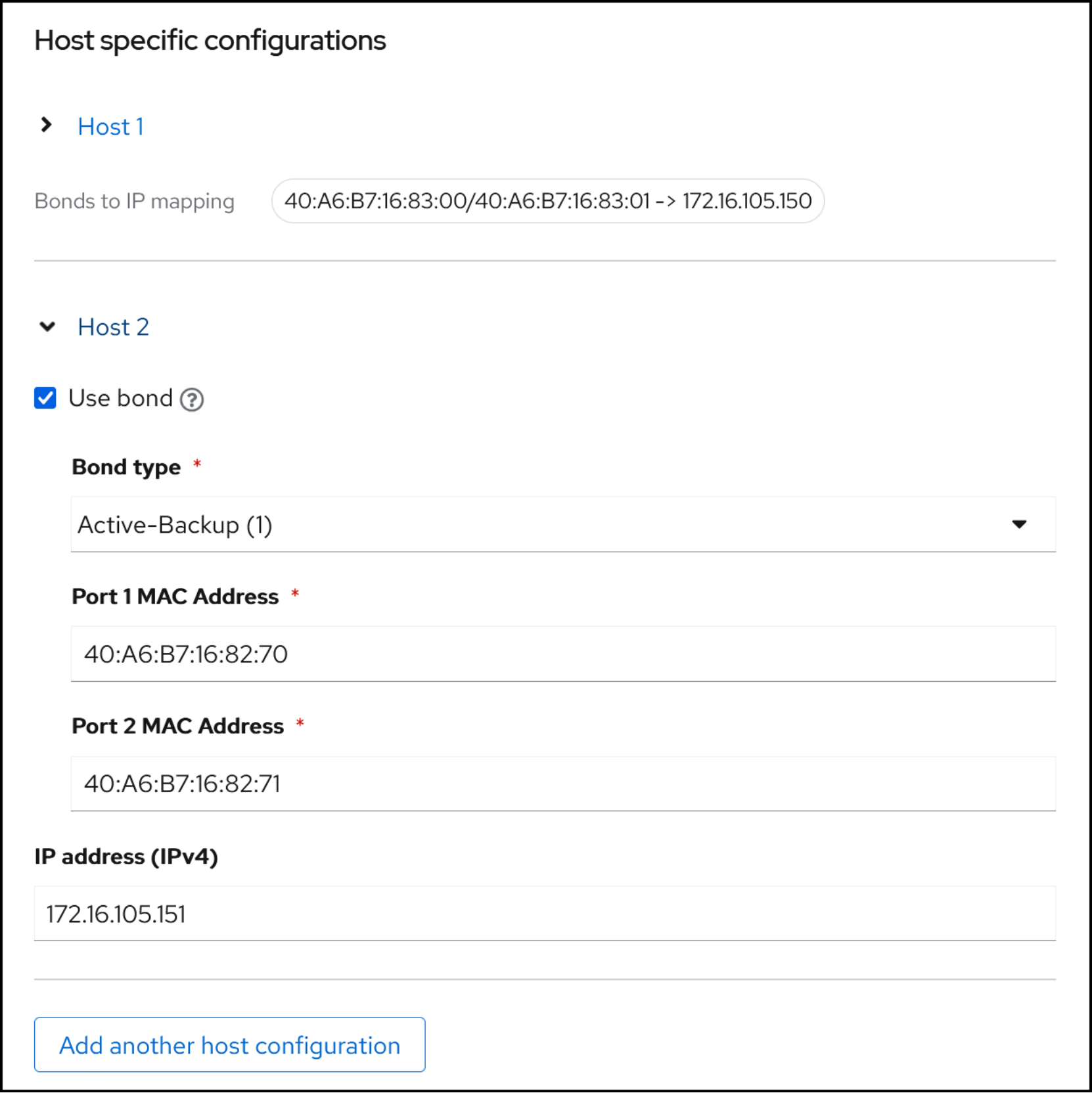
Figure 12. Step 2b – Cluster creation
Step 3 Operators
In this step you choose the Operators, which have bundles of software that enable specific features. We want to run both containerized applications and VMs in this cluster, so we check the Virtualization bundle. There are 26 Single Operators that you may choose from. Expand the list to check individual Operators such as Logical Volume Manager Storage. Checking the Virtualization bundle activates twelve required Operators. Click Next.
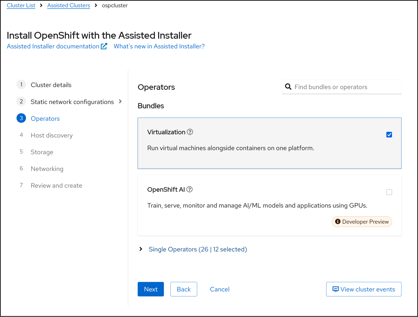
Figure 13. Step 3 – Cluster creation
Step 4 Host discovery
The Assisted Installer discovers hosts through a discovery ISO. You mount this ISO on each of your OpenShift bare metal hosts, and it boots to a temporary Red Hat OS. The Installer queries for the hosts by the IP address you supply in Figure 11. Begin by clicking the Add hosts button under Host discovery. This will start another wizard that guides you to download the Discovery ISO.
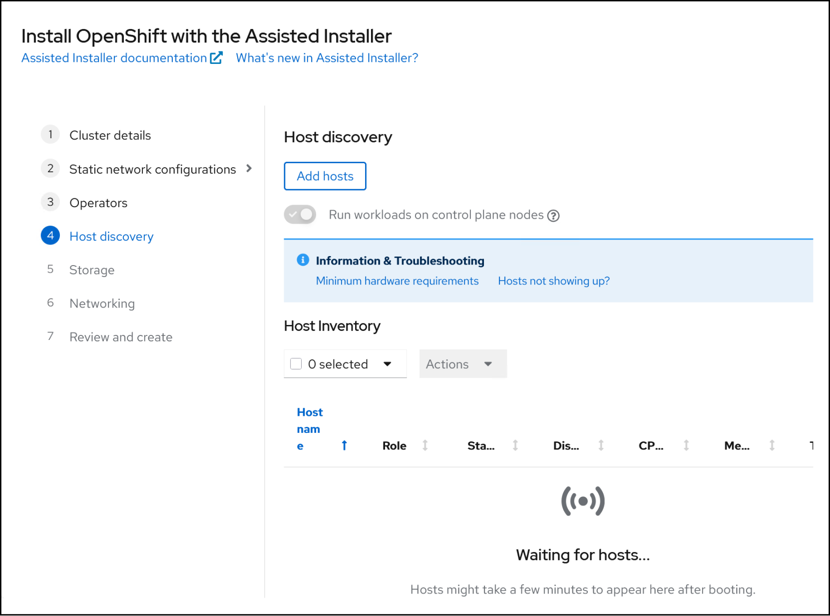
Figure 14. Step 4 – Cluster creation
In the first dialog, select a Provisioning type. It defaults to Minimal image file which Dell recommends. It is about 130 MB in size. Supply an SSH public key as detailed in OpenShift node access.
The dialog also offers settings for proxy and certificates if appropriate for your environment. Click Generate Discovery ISO in Figure 15.
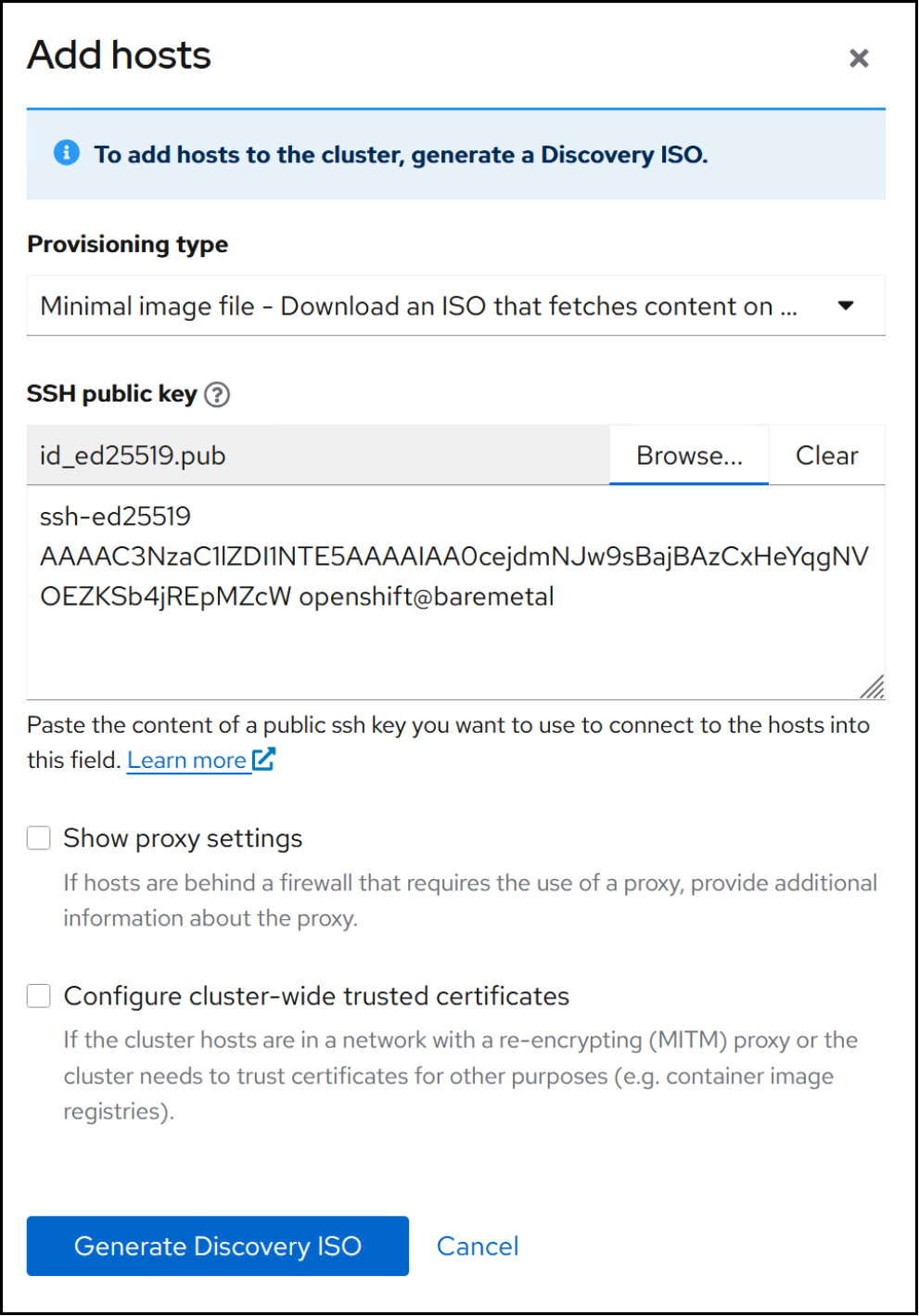
Figure 15. Step 4a – Cluster creation
The creation of the ISO is a quick process. The installer presents a second dialog so that you can download the ISO either through the browser or wget. Choose a method and download the ISO to a location that has access to the management interface of the OpenShift nodes, e.g., iDRAC.
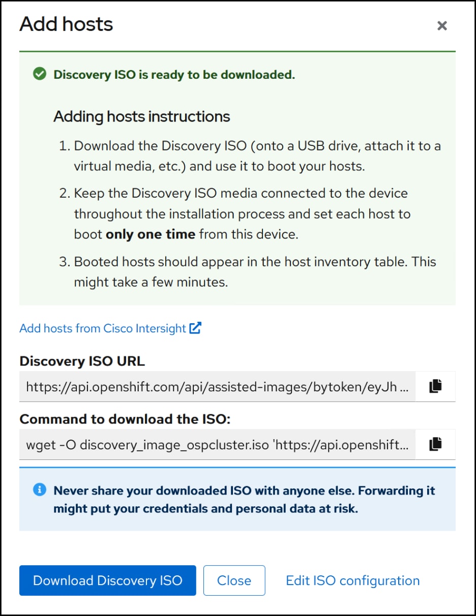
Figure 16. Step 4b – Cluster creation
Next, mount the ISO to the designated nodes, and reboot to the ISO. In this cluster there are three bare-metal machines. Below is an example of the first node in this cluster. Note the new bond, bond0 on VLAN 105, with the correct IP in Figure 17 after the initial configuration completes. At this point, the installer will be able to discover the node.
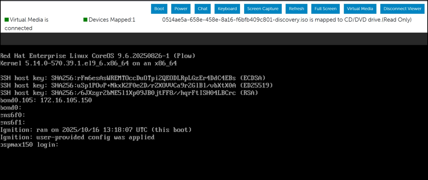
Figure 17. Step 4c – Cluster creation
Be sure all nodes reach this point after booting to the ISO. The installer takes a few minutes to recognize the nodes, but when it does, they will appear in the wizard. Wait for the Status to show Ready in Figure 18. As the installer discovers the hosts, it may display other statuses such as Not Ready until it finishes the initial configuration. If the installer detects an issue, the status will remain as something other than Ready at which time you should troubleshoot using the OCP documentation found in the References. It is also possible for the installer to show Ready but also include warnings. Click Next.
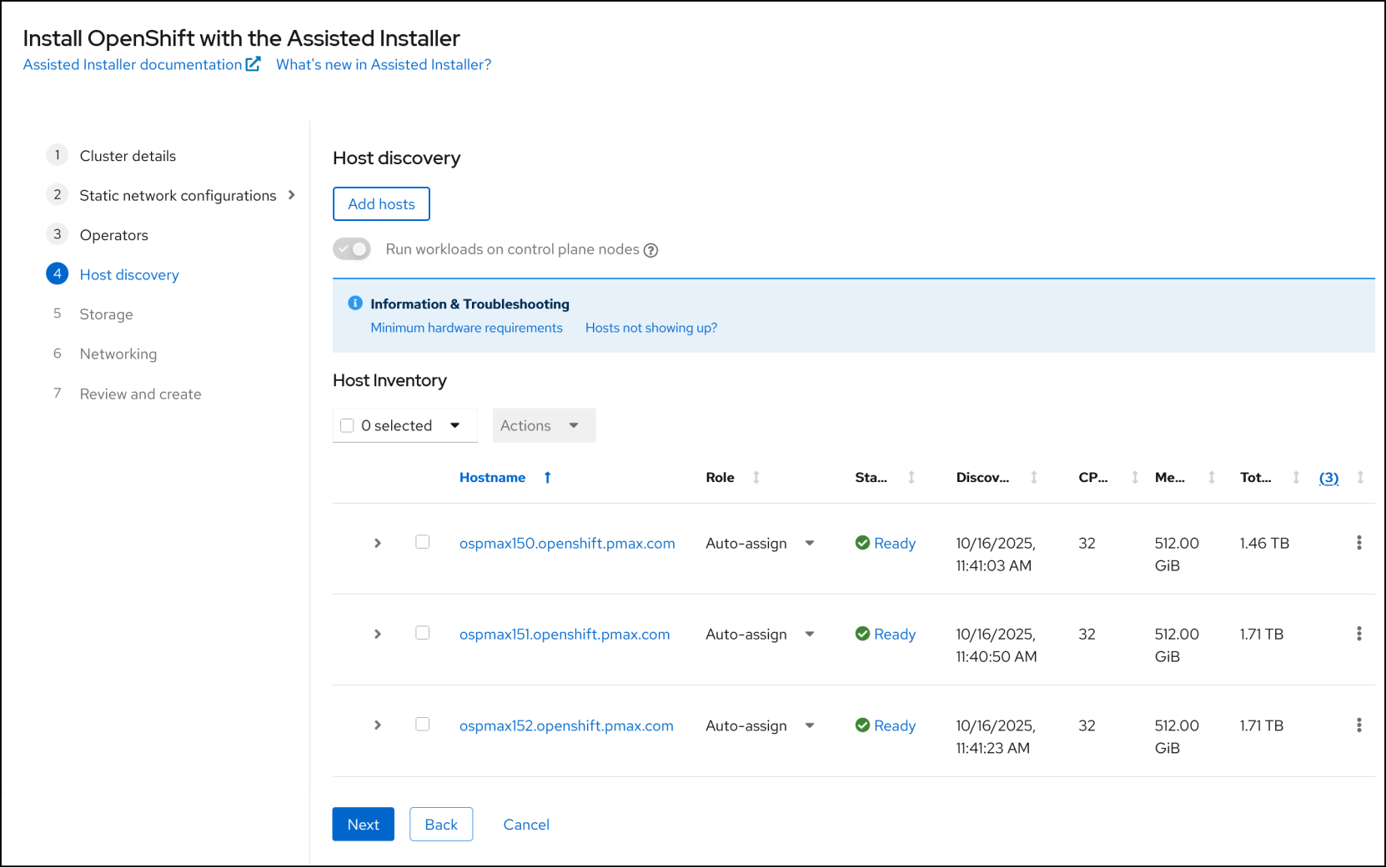
Figure 18. Step 4d – Cluster creation
Step 5 Storage
- In the storage step it is usually unnecessary to make any modifications because the installer will use the internal disk if it meets the size requirements. The OpenShift Container Platform
- OpenShift Virtualization - Reference Implementation Guide
- Offload README
Appendix covers the use case where external disks exist. The installer warns the user that it will format all bootable disks. If you wish to review the inventory before proceeding, use the greater than symbol (>) to expand each server. Click Next.
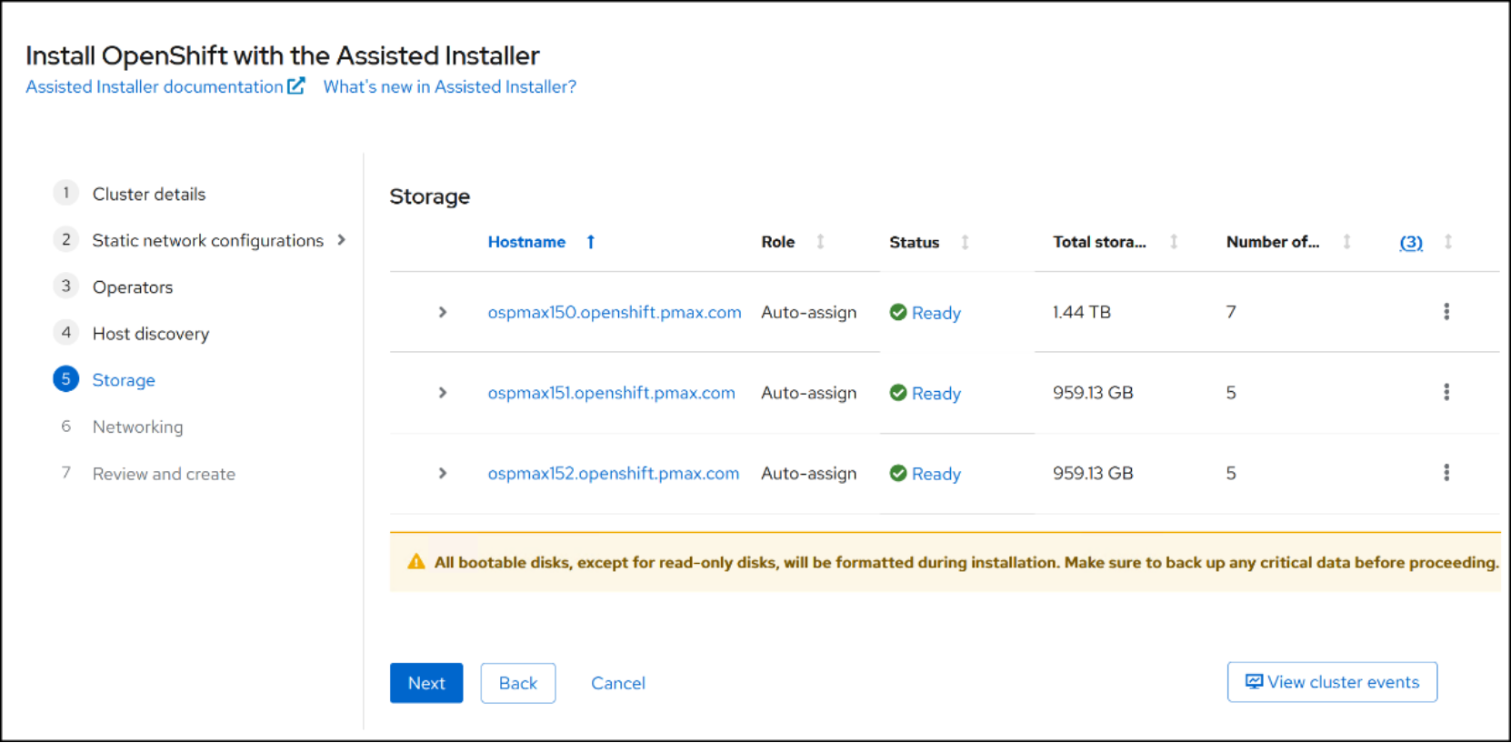
Figure 19. Step 5 – Cluster creation
Step 6 Networking
In the Networking page you must decide whether you or the cluster will manage the network. Dell recommends the Cluster-Managed Networking for most implementations. The Network stack type defaults but choose a Machine network from the drop-down menu. You will need two additional IPs for the API and Ingress. If needed, there are advanced networking capabilities you can explore by checking the box.
The bottom half of Figure 20 includes the discovered hosts. The installer runs a few preliminary checks on them, specifically a test for clock synchronization. If this fails, as below, the installer grays out the Next button. You can see the Status of one of the hosts is Insufficient because its clock is too far askew from the other two.
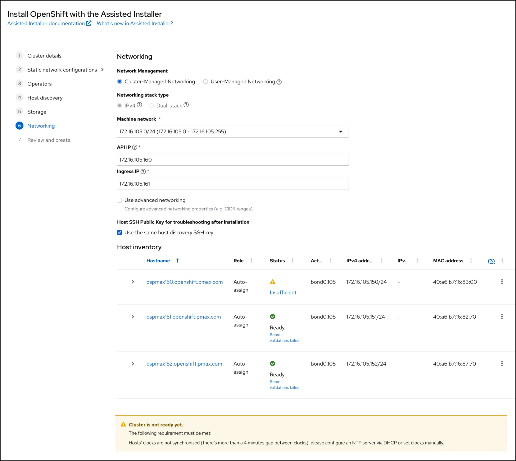
Figure 20. Step 6 – Cluster creation
To resolve this error, you need to manually add an NTP server. You can do this by clicking the hyperlink below the Ready status where it says Some validations failed. A pop-up shows you that there is no NTP server. Click Add NTP sources in Figure 21 and enter the IP address. Click Add. You only need to do this once on any of the hosts as the NTP server is then set on all of the nodes in the cluster.
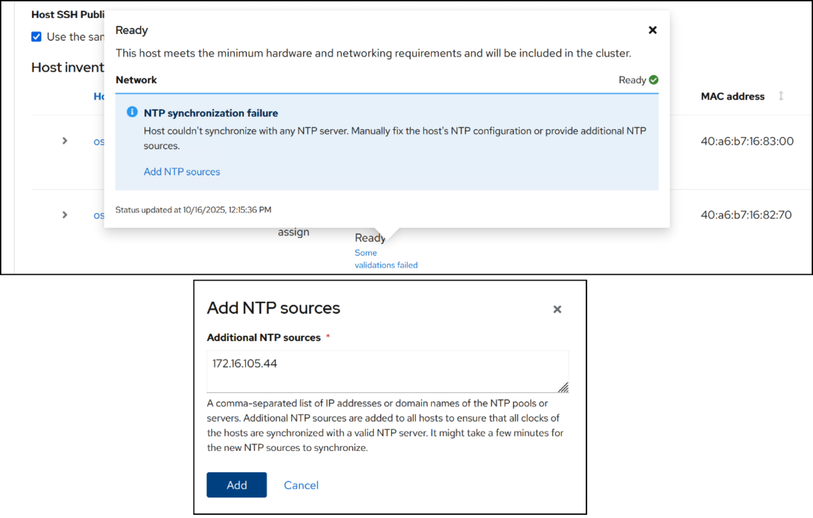
Figure 21. Step 6a – Cluster creation
After you add the NTP server, it will take a few minutes for all hosts to synchronize with the NTP. Eventually the installer will remove the validation error, and all hosts will enter Ready status. Note that the yellow box error at the bottom may remain a bit longer while the clock on that insufficient host synchronizes; but until it disappears you will be unable to click Next.
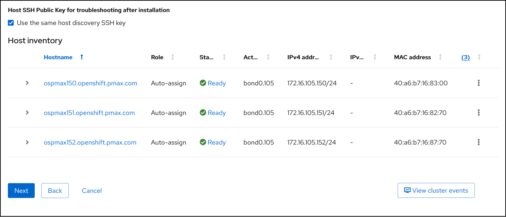
Figure 22. Step 6b – Cluster creation
Step 7 Review and create
In the last step, the installer runs a number of pre-checks to ensure the installation is likely to succeed. You can review the summary of each major section before clicking Install cluster. Once you do that, a small notice appears to the right indicating the start and the Install cluster button turns gray. The image below only includes a couple of the summary sections for brevity.
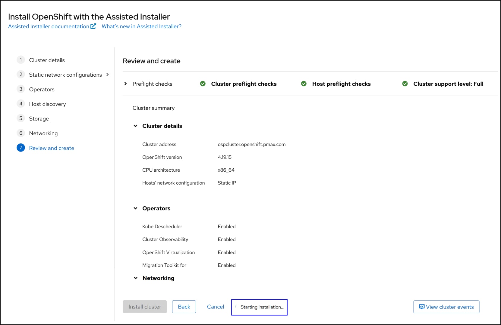
Figure 23. Step 7 – Cluster creation
You can watch the installation progress in the Hybrid Cloud Console. When it completes, it will show the host inventory in Figure 24, and you can launch the OpenShift Web Console.
Note: You will need to be sure that the DNS has the necessary entries to access the console URL, or alternatively that you add the names to the local hosts file on the bastion server. Click on the Not able to access the Web Console hyperlink to get a list of the required entries. You can find an example of the DNS entries in the Appendix section DNS entries.
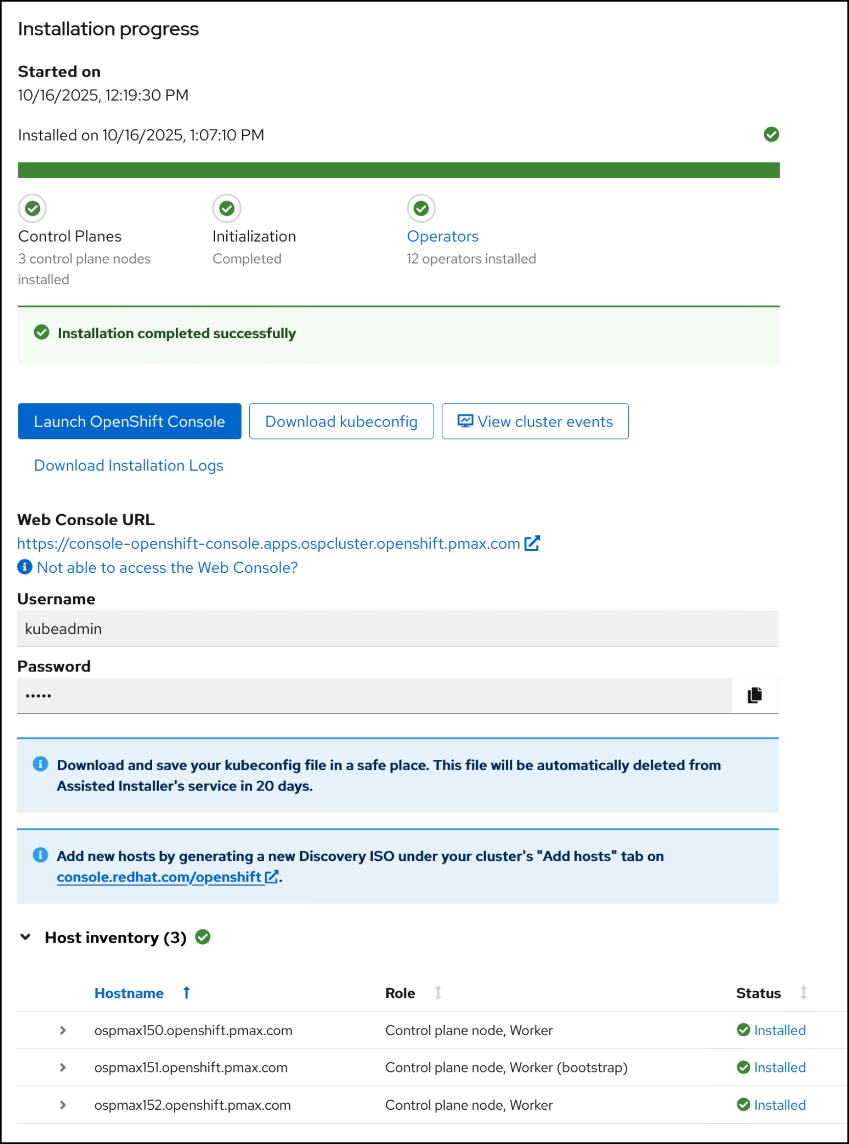
Figure 24. Cluster installation completion
If it becomes necessary to scale the OCP cluster, you can expand it in much the same manner as the original installation. The next section covers this.
Scaling
OCP cluster expansion is straightforward. The process to add a node mirrors the installation, allowing you to scale workers to handle increased VM and containerized workloads. Since adding nodes to OCP clusters is a common occurrence, we cover it here for completeness of deployment.
Step 1
Login to the Red Hat Hybrid Cloud Console. In the left-hand menu (see Figure 7), navigate to Cluster Management -> Cluster List -> <cluster_name>, ospcluster here. In the right-hand panel, click on the Add Hosts tab, and then the Add hosts button.
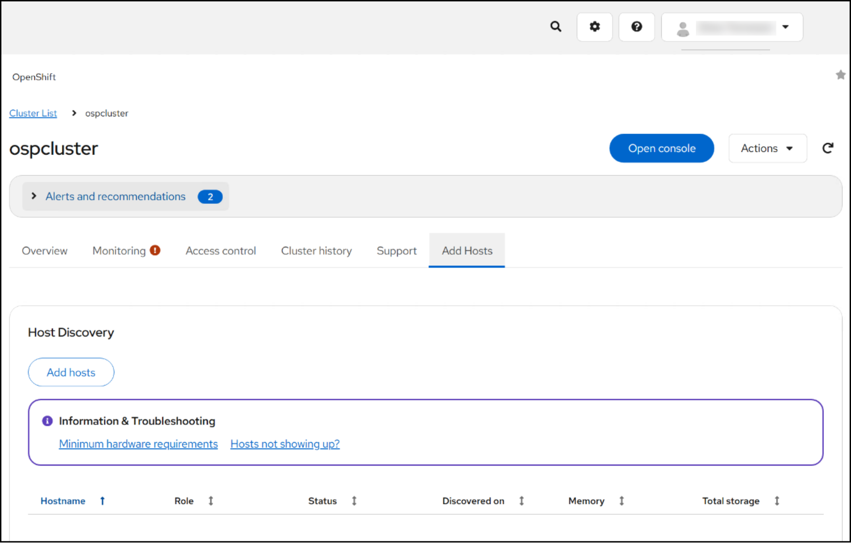
Figure 25. Step 1 – Add OCP host
Step 2
Choose your CPU architecture and the type of networking using the radio buttons below. Click Next.
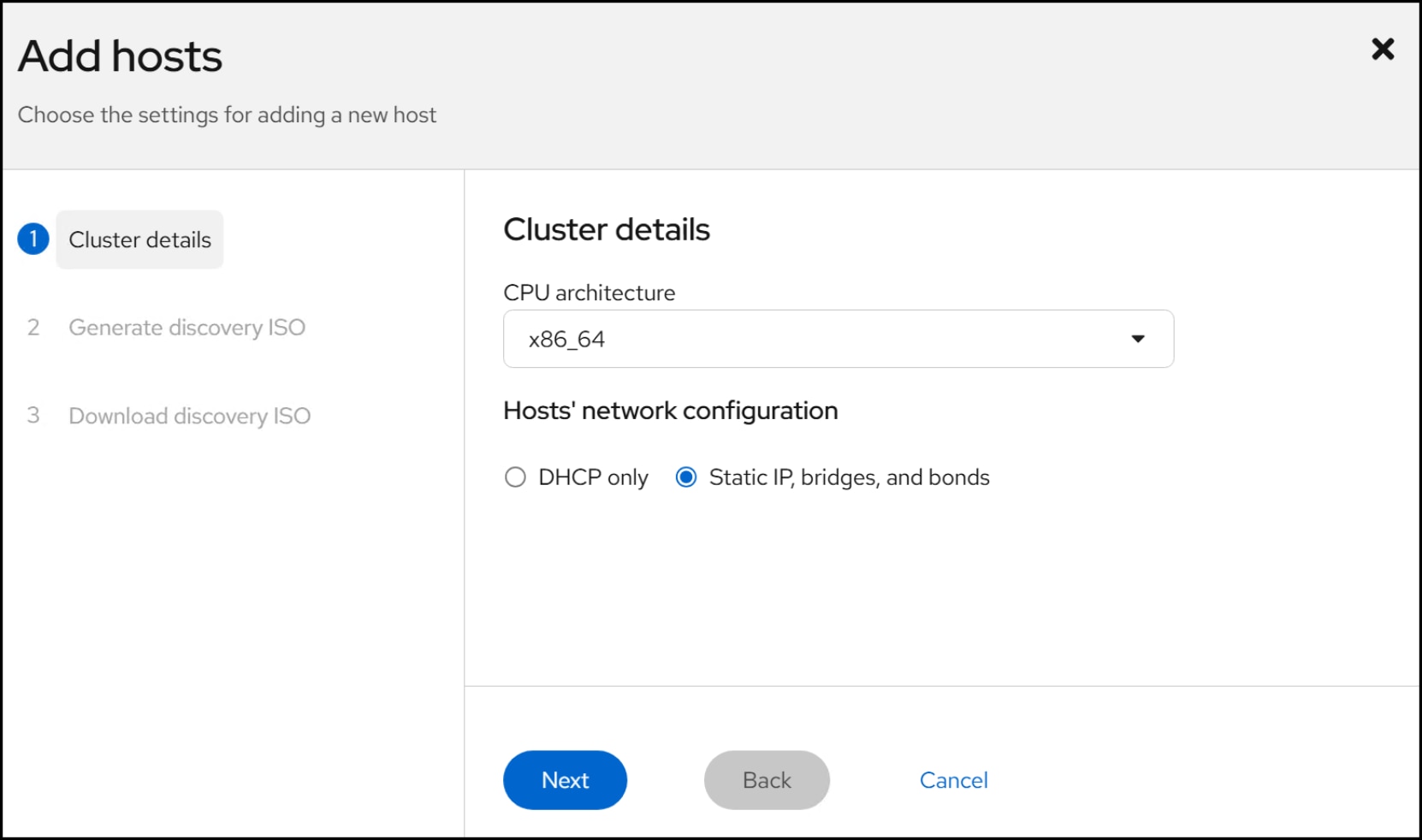
Figure 26. Step 2 – Add OCP host
Step 3a Static network configurations: Network-wide configurations
In step 3 add the network information. This step is two parts, the network-wide (same as existing cluster) and the host specific. Start by selecting either the Form or YAML view. As the callout notes, use YAML if you are doing something more advanced with your node. For an example, we will use Form. Enter in the networking details, mirroring your original deployment of OCP. Click Next when done.
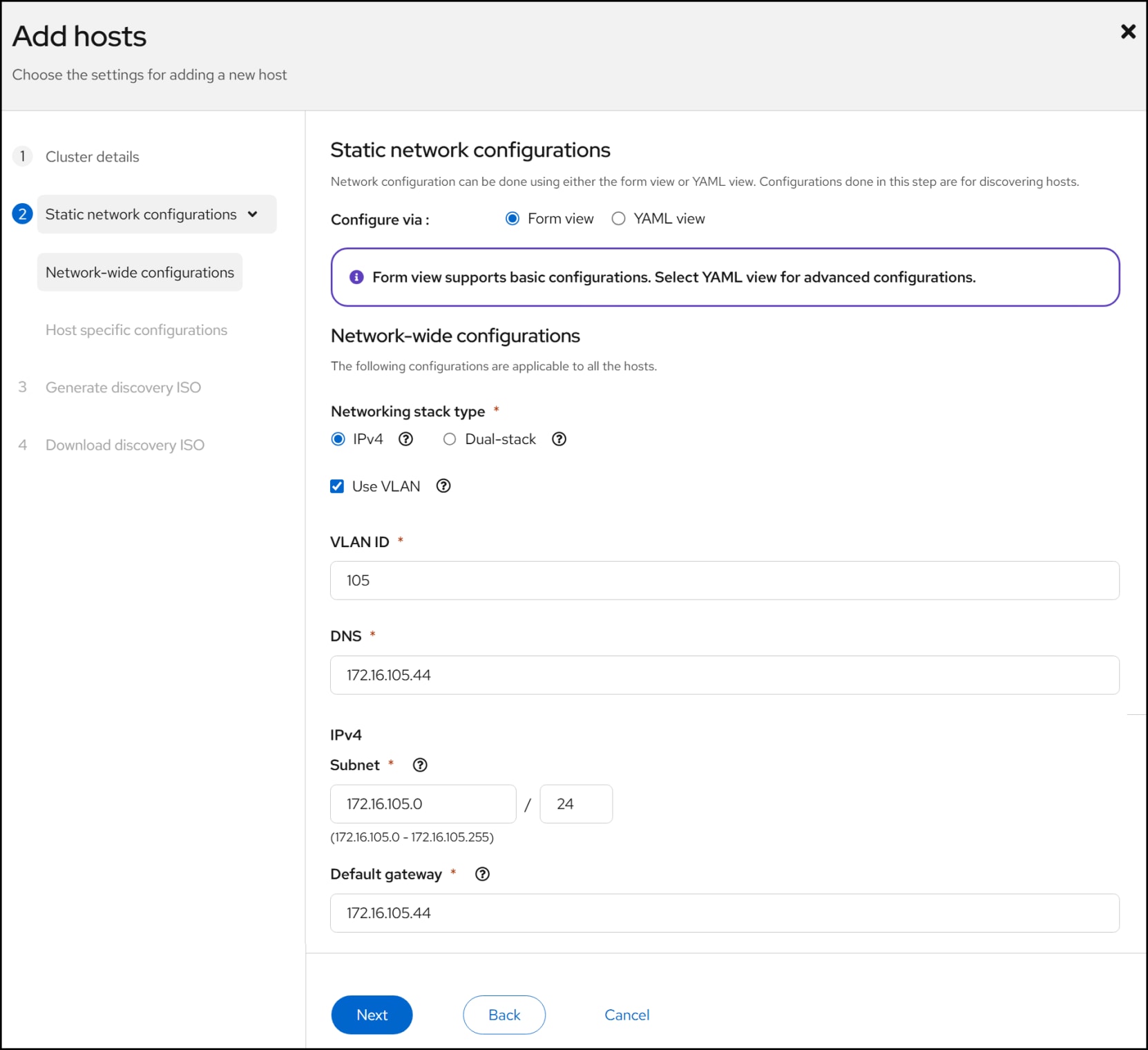
Figure 27. Step 3a – Add OCP host
Step 3b Static network configurations: Host-specific configurations
Next, enter the host specific information. This includes the MAC addresses (two for bonding) and the host IP. You can also add more hosts here if desired. Click Next to continue.
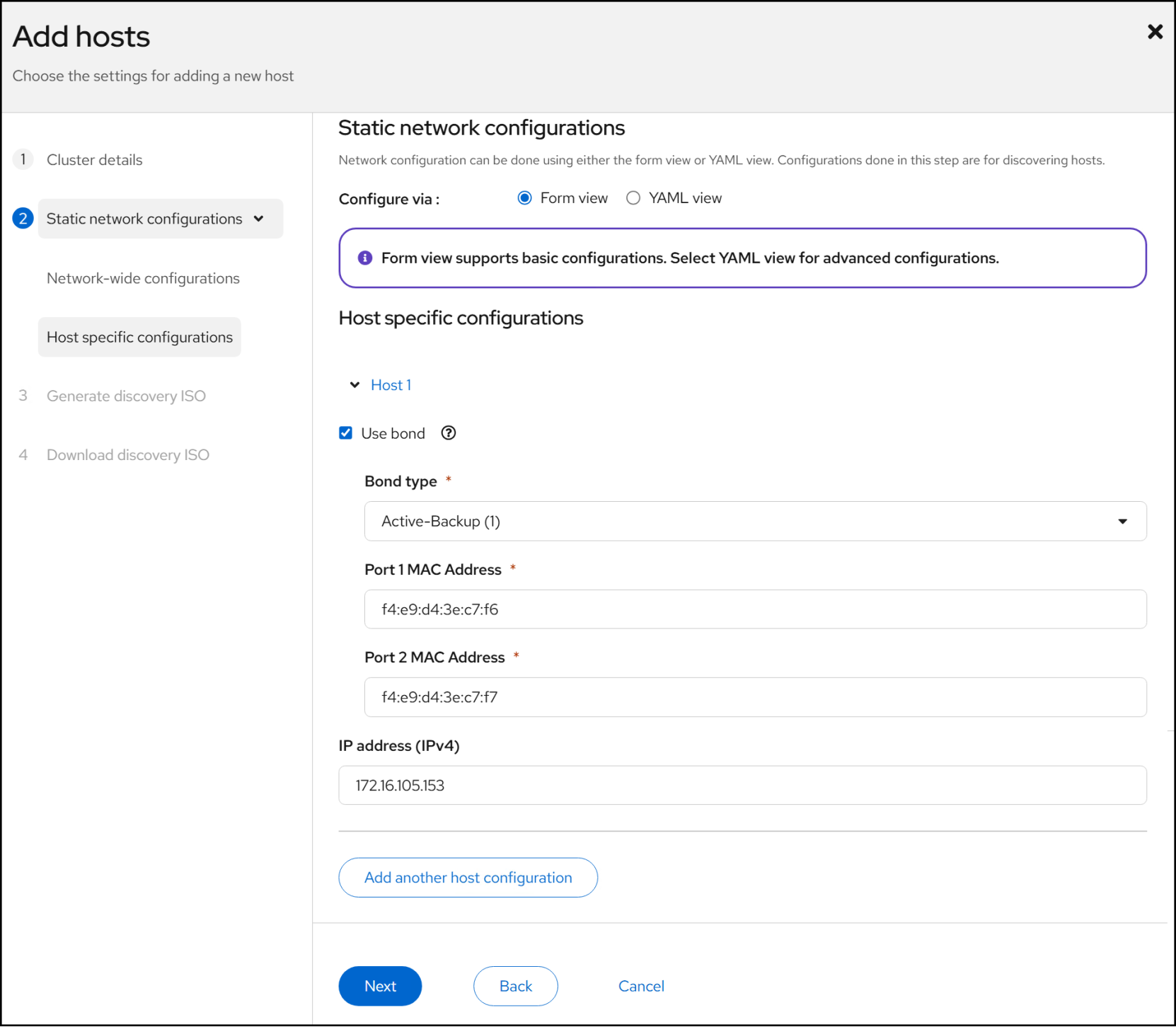
Figure 28. Step 3b – Add OCP host
Step 4
Begin by selecting a Provisioning type. Dell recommends using a minimal image file. Provide the SSH public key currently in use for the other nodes and then click on Generate Discovery ISO.
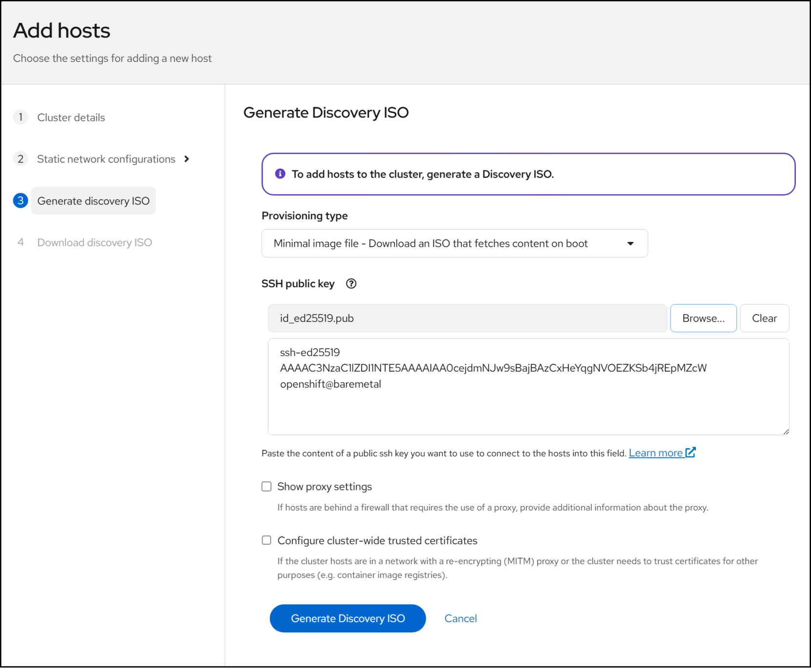
Figure 29. Step 4 – Add OCP host
Step 5
Finally, click on Download Discover ISO to pull the ISO through the browser. Alternatively, the wizard offers a direct URL or wget access.
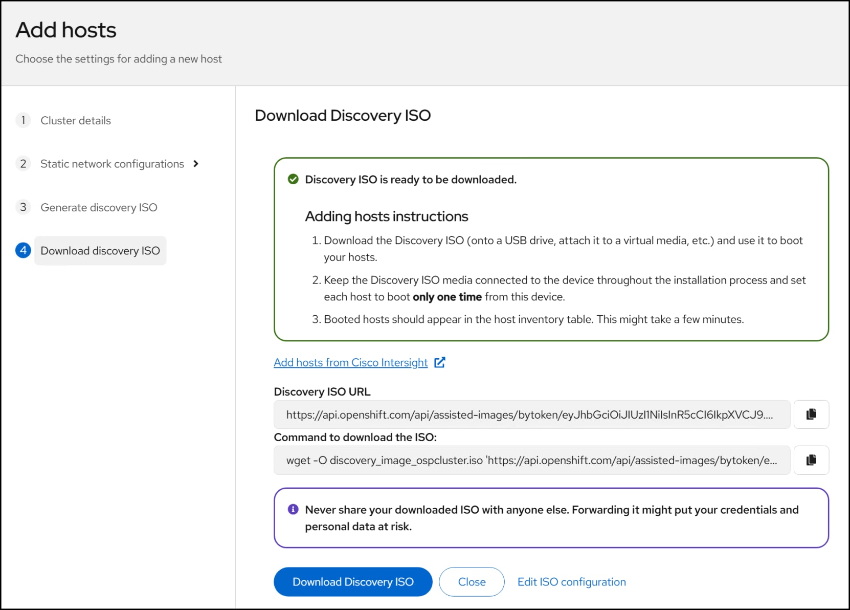
Figure 30. Step 5 – Add OCP host
Step 6
Using the downloaded ISO, mount it to your chosen host and boot to it. As with the original cluster installation, it is non-interactive. You simply need to watch the Add Hosts screen for the new host to appear. If you receive a validation error as in Figure 31, review and resolve. Here, we had to configure NTP. Wait for the clocks to sync, at which point the validation error will disappear. Note that unlike the Insufficient status in Figure 20, if you are just missing an NTP server it will let you continue. Dell does not recommend doing this, however. Click the Install ready hosts button.
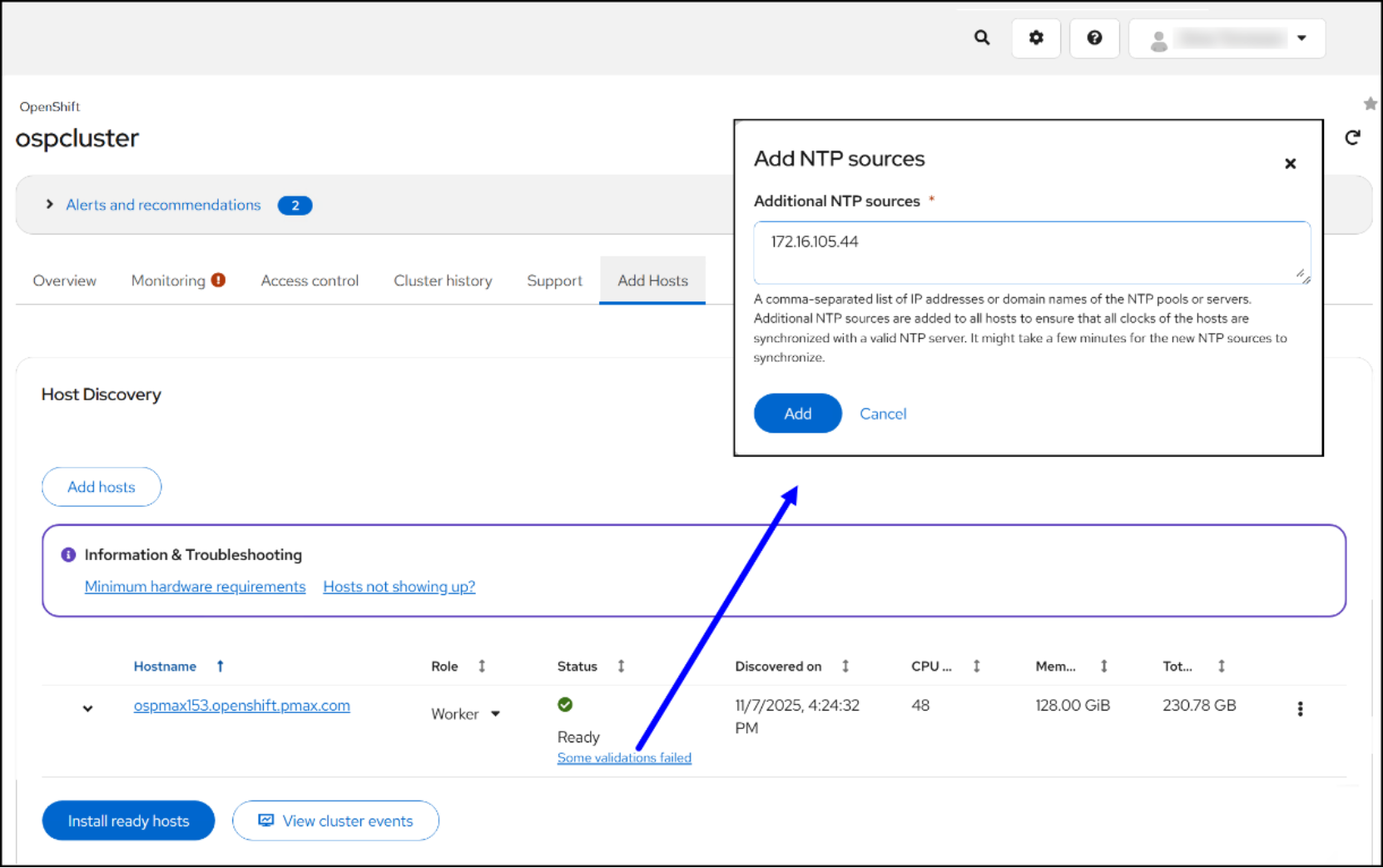
Figure 31. Step 6 – Add OCP host
Step 7
The installation does not take long to complete; however, even though the status will return as Installed, you may have to wait for the final reboot before the last step. Click on the View cluster events button to see when the reboot began. Until the system is up again, the cluster will not issue signing requests.
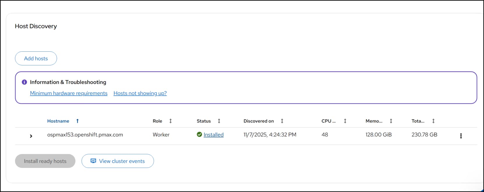
Figure 32. Step 7 – Add OCP host
Step 8
Finally, open the cluster console. Navigate to Compute -> Nodes in the left-hand menu. In the right-hand panel you will see the existing nodes. When the reboot completes on the new node, it will appear in the list. Initially the console will show the state as Discovered. Below the state will be the message: Approval required. In order to join the node to the existing cluster, it issues certificate signing requests, csrs. There are two requests it will issue. First, on discovery, and then to make the node Ready. Once you approve the first CSR, the node will be Not Ready. Approve the second CSR and wait for the node to come back as Ready. We include the steps in Figure 33. Note that you can also use CLI to view and approve the CSRs:
- oc get csr
- oc adm certificate approve <certificate>
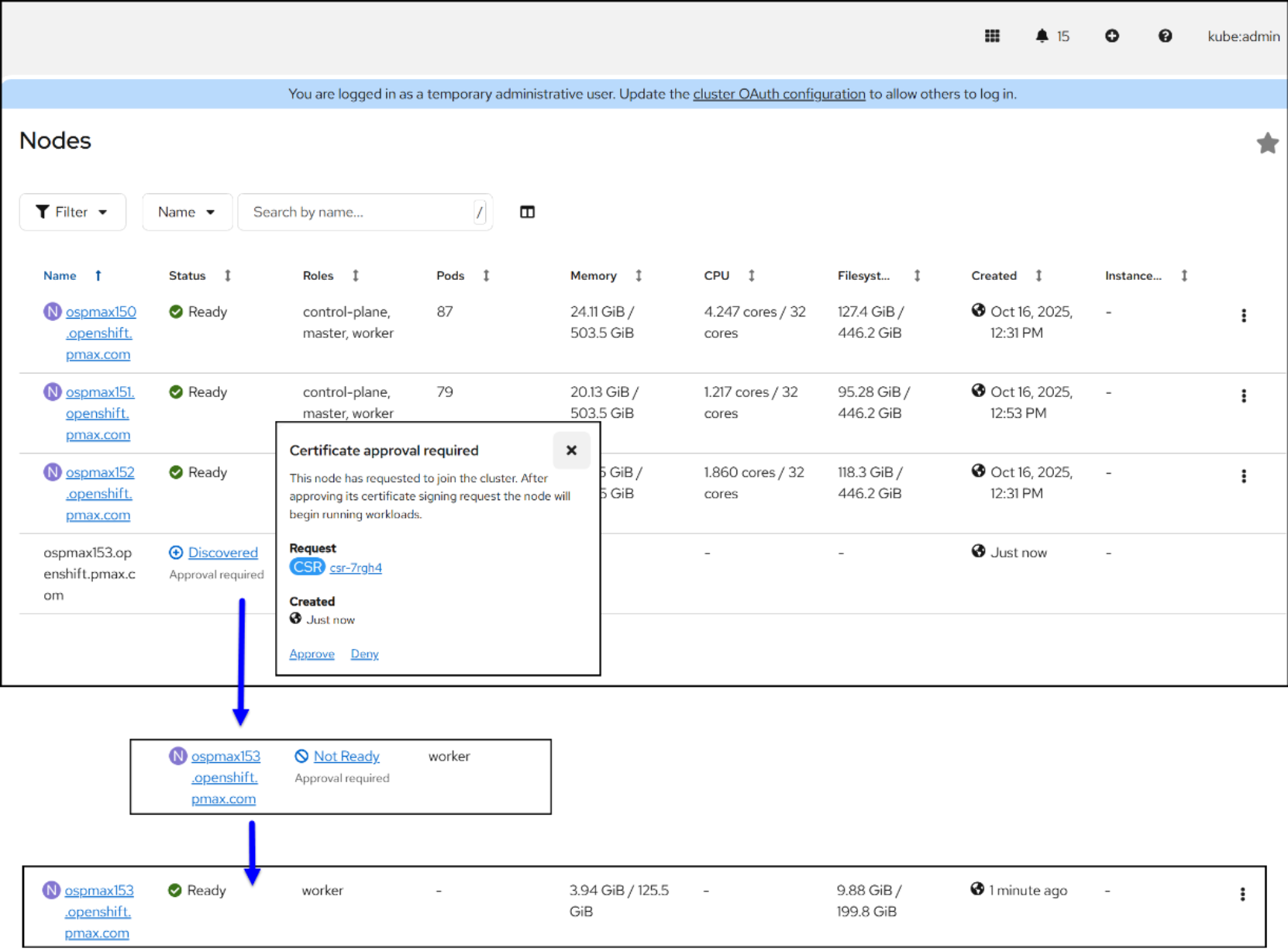
Figure 33. Step 8 – Add OCP host
The three node cluster is now a four node cluster and ready for additional workloads.

Figure 34. Updated four node cluster
Access host
While you can manage most aspects of the OCP through the UI, there are tasks you will need to perform using either kubectl or the OpenShift Client (oc). If you only wish to use one client, oc adds specific OpenShift features which kubectl does not have access to. You can run the utilities on Windows or Linux or even MacOS.
In the RedHat Hybrid Cloud Console, navigate to Resources -> Download in Figure 35.
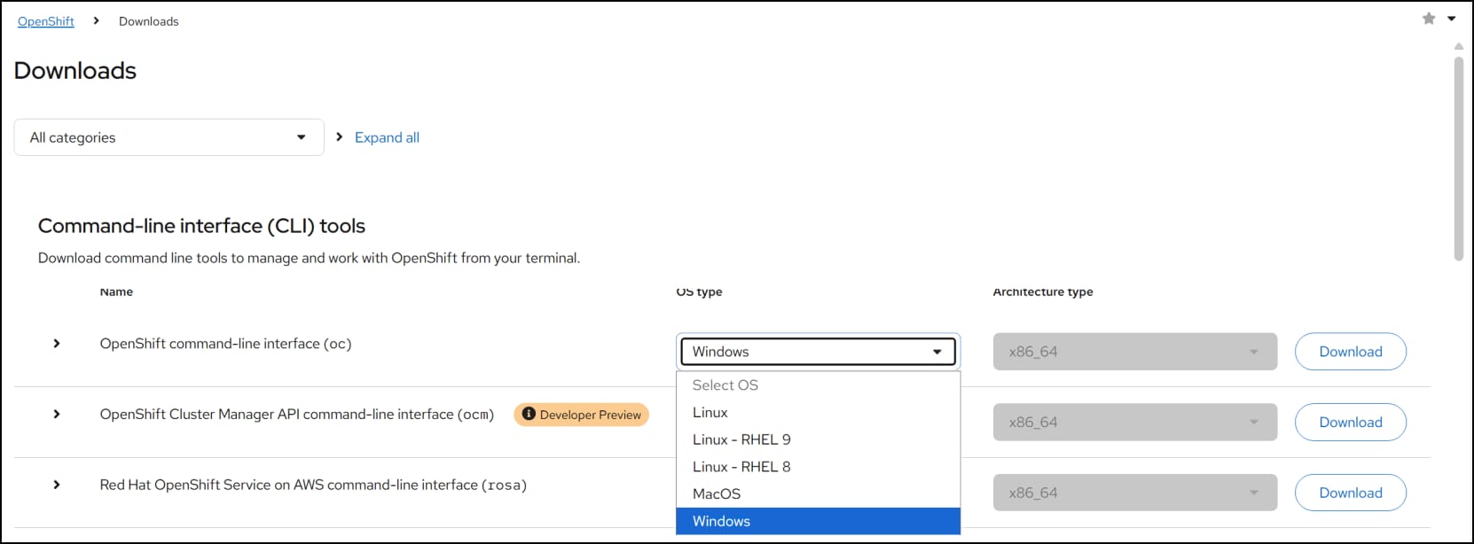
Figure 35. OC download
Simply copy over the Kube configuration from the cluster to your VM or server that has network access to the cluster. We used a SUSE 15.6 VM here, but any OS distribution is acceptable, including using AMD. It’s advisable to set up the host prior to deployment because it is useful for the public key creation that allows SSH access to the hosts after installation.
OpenShift node access
One of the peculiarities of an OpenShift implementation as detailed here is that you cannot simply SSH into a node as root or another user like you would in other Kubernetes clusters. OCP locks down that type of access which is why it is essential to set up an SSH public key you can supply to the installer. If you keep this key on your access host, it will permit you to SSH into the nodes as the “core” user and then run commands as sudo. There are situations that will require you to do this, particularly if there are networking problems you must diagnose. To create this key, you can follow these simple steps:
[root@dsib0111 ~]# ssh-keygen -t rsa -b 4096 -C "dell-user@dell.com"
Generating public/private rsa key pair.
Enter file in which to save the key (/root/.ssh/id_rsa):
Enter passphrase for "/root/.ssh/id_rsa" (empty for no passphrase):
Enter same passphrase again:
Your identification has been saved in /root/.ssh/id_rsa
Your public key has been saved in /root/.ssh/id_rsa.pub
The key fingerprint is:
SHA256:n3jair3L/5WG3TPLuMO/xRk1yuaDg4QE+ezddO/Djio dell-user@dell.com
The key's randomart image is:
+---[RSA 4096]----+
| .. |
| .. |
| o. ..|
| .o. .... o|
| ..S.o .+.. |
| ..+.o+o =o|
| ..+oooB++|
| + E .==+=|
| . B=+oo+=*o|
+----[SHA256]-----+
[root@dsib0111 ~]#
You will supply the file /root/.ssh/id_rsa.pub to the installer at the appropriate step. You will then be able to ssh into the OCP nodes:
ospmax170:~/.kube # ssh core@ospmax151.openshift.pmax.com
Red Hat Enterprise Linux CoreOS 9.6.20250930-0
Part of OpenShift 4.19, RHCOS is a Kubernetes-native operating system
managed by the Machine Config Operator (`clusteroperator/machine-config`).
WARNING: Direct SSH access to machines is not recommended; instead,
make configuration changes via `machineconfig` objects:
https://docs.openshift.com/container-platform/4.19/architecture/architecture-rhcos.html
---
Last login: Fri Oct 24 13:45:24 2025 from 172.16.105.170
[systemd]
Failed Units: 1
NetworkManager-wait-online.service
[core@ospmax151 ~]$
Deploying the PowerMax CSI Driver
Introduction
PowerMax CSI
The Container Storage Interface, or CSI, is an industry standard for exposing block and file storage to containerized applications like Kubernetes, a Container Orchestration System. The CSI drivers implement an interface between CSI-enabled Container Orchestrator (CO) and storage arrays. It is a plug-in you install into Kubernetes to provide persistent storage using a Dell storage system like PowerMax. The PowerMax CSI driver supports most protocols, capabilities, and access modes. Please see the Dell documentation here for details.
Container Storage Modules enhance the CSI to provide advanced enterprise storage features for Kubernetes clusters. It includes software modules that extend beyond CSI, offering enterprise storage capabilities to Kubernetes users. These modules are Authorization, Replication, Snapshotting, Resiliency and Observability.
The CSI driver installation instructions vary depending on the underlying Kubernetes environment. When installing on OpenShift, you use the CSM Operator. You install the CSM from the OperatorHub within the RedHat Hybrid Cloud Console.
Note: When implementing the PowerMax CSI driver, we chose Fibre Channel which is the most common protocol on the PowerMax platform. You can also use iSCSI or NVMeoF as protocols if preferred. Note, however, that some Red Hat dev or tech preview features do not support all protocols.
CSM Operator
Follow these steps to install the CSM Operator.
Step 1
Open the Operators -> OperatorHub from the left-hand menu (see Figure 3) and in the right-hand screen, search for DELL. There should be two results, a certified CSM and community CSM. Click on the certified CSM.
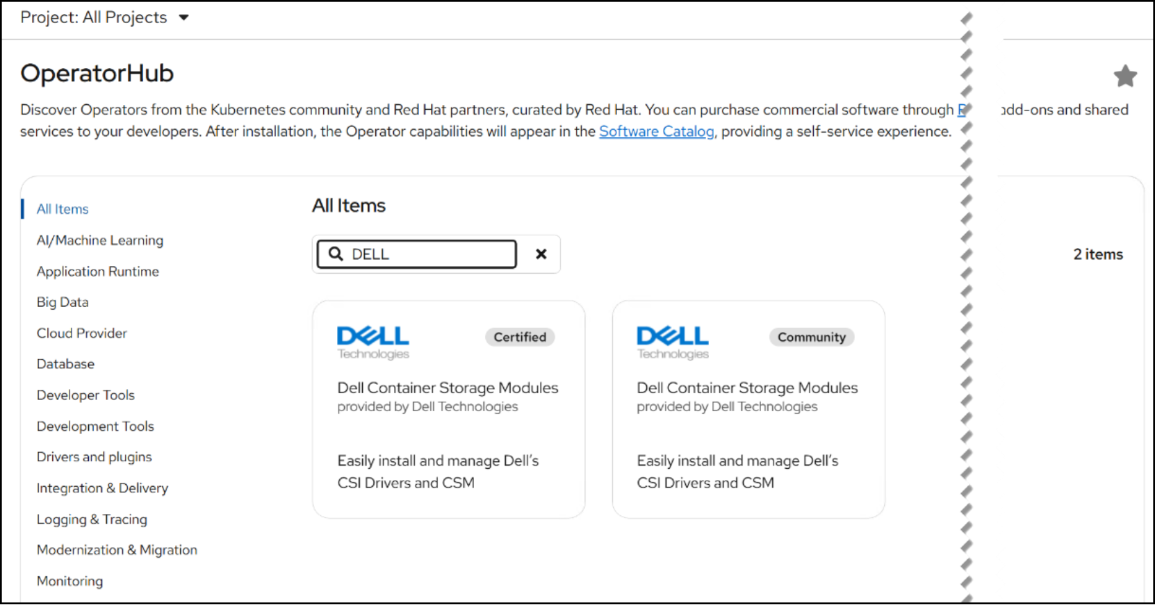
Figure 36. Step 1 – Dell CSM Operator
Step 2
From the Dell CSM inset in Figure 37, click Install.
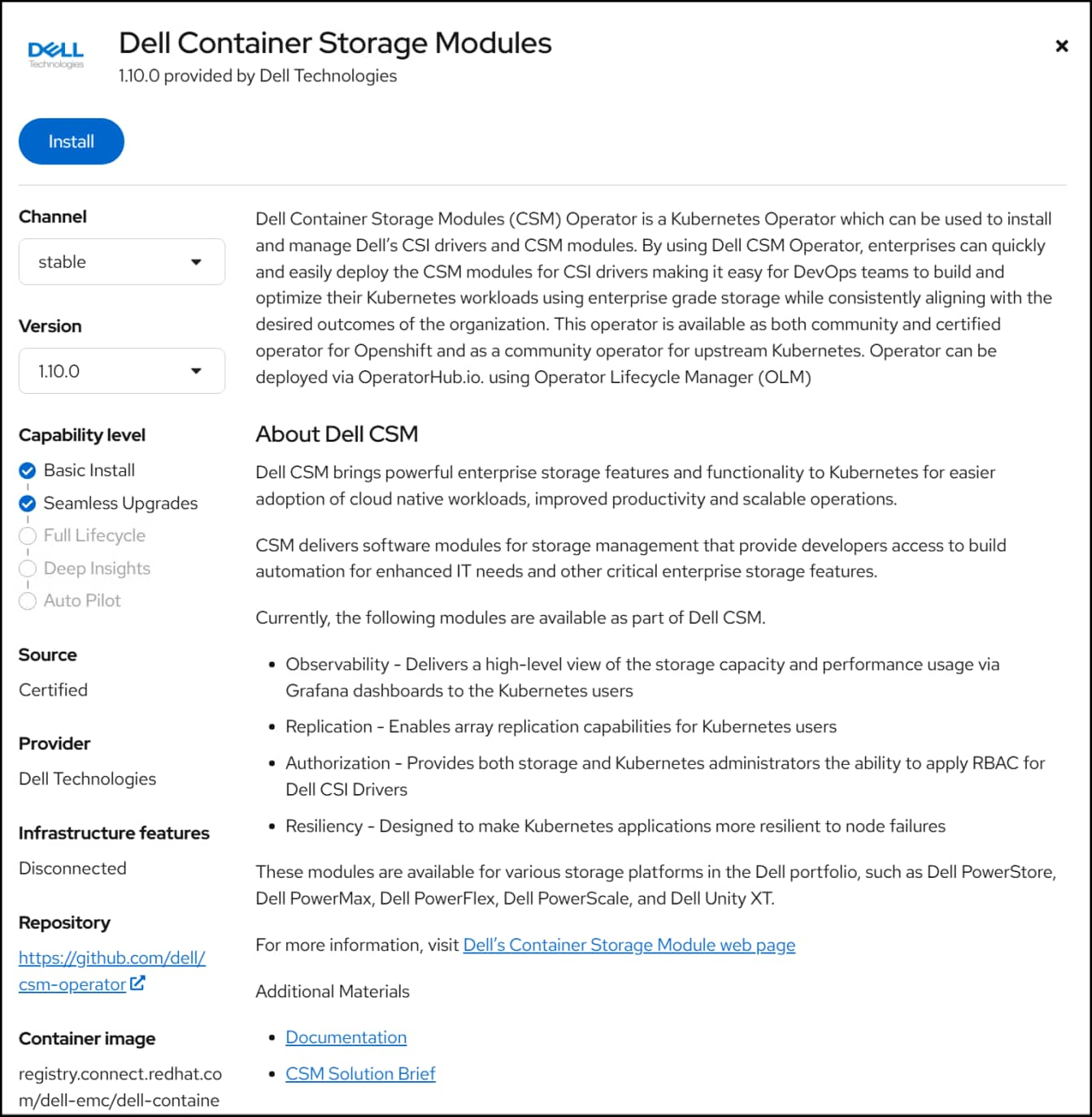
Figure 37. Step 2 – Dell CSM Operator
Step 3
Review the installation details in Figure 38 and click Install again to finalize.
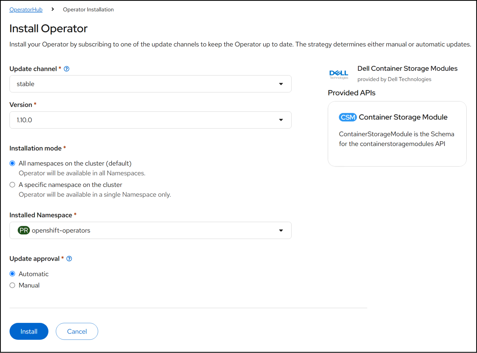
Figure 38. Step 3 – Dell CSM Operator
When complete, the UI will display the result as below.
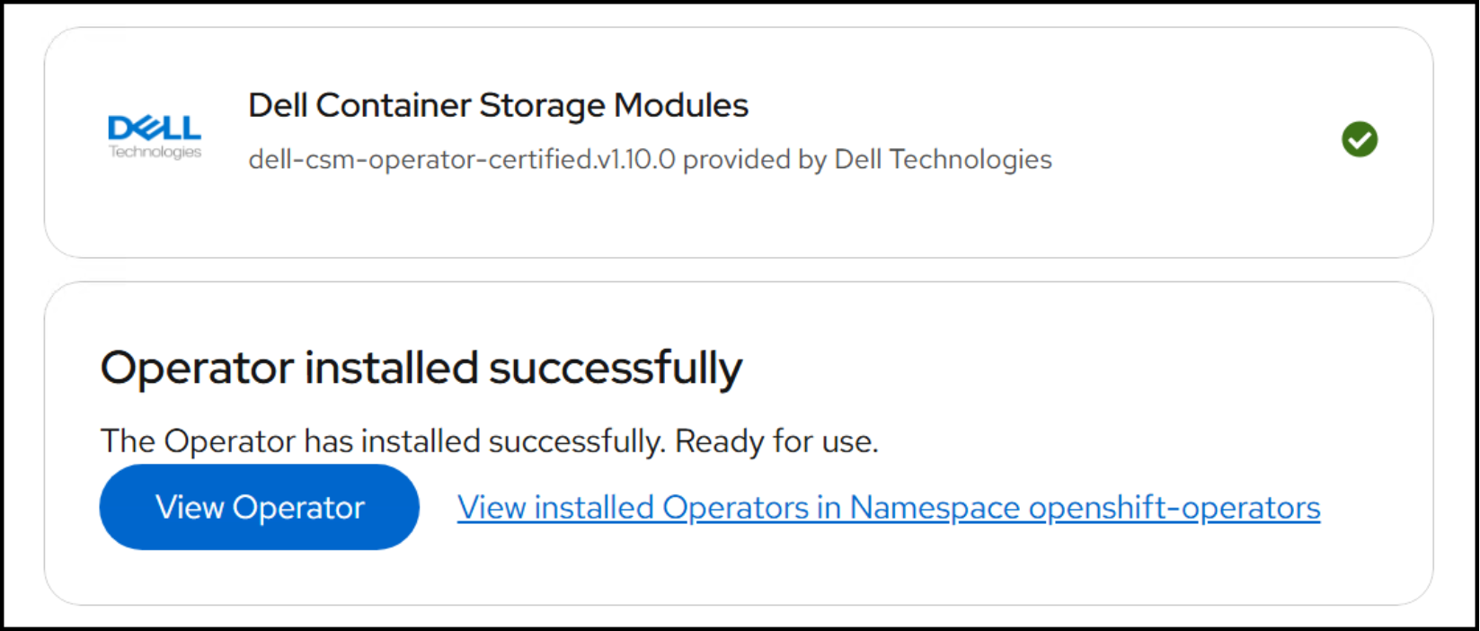
Figure 39. Complete Dell CSM Operator
After a successful installation, proceed with the CSI installation.
CSI installation
Dell provides documentation on the installation of the PowerMax CSI driver which you can locate at this link. This documentation may vary based on the CSM version. As of this writing, the current version is 1.15.1. Since this paper uses the basic functionality of the CSI driver and no CSM modules, we include the steps below for ease of reference; however, always refer to the official documentation if you encounter any issues.
Reverse Proxy
Unlike the other Dell CSI drivers, the PowerMax requires a Reverse Proxy. The function of the proxy is to regulate the REST API calls sent to the Unisphere instance. It can queue these requests to enhance the performance of the driver.
Step 1
Install the certificate manager:
kubectl apply -f https://github.com/cert-manager/cert-manager/releases/download/v1.16.1/cert-manager.yaml
Step 2
Create an SSL certificate and private key. You will supply this later in the installation when creating a TLS secret.
Generate a configuration file (e.g., openssl.cnf). Here is an example. You can use this without modification if you wish.
[ req ]
default_bits = 2048
distinguished_name = req_distinguished_name
req_extensions = req_ext
prompt = no
[ req_distinguished_name ]
C = XX
L = Default City
O = Default Company Ltd
[ req_ext ]
subjectAltName = @alt_names
[ alt_names ]
DNS.1 = "csipowermax-reverseproxy"
IP.1 = "0.0.0.0"
On a Linux host with openssl, generate the certificate and private key. Be sure to note the location as you will use them in a later step.
openssl genrsa -out tls.key 2048
openssl req -new -key tls.key -out tls.csr -config openssl.cnf
openssl x509 -req -in tls.csr -signkey tls.key -out tls.crt -days 3650 -extensions req_ext -extfile openssl.cnf
Fibre channel MPIO
The following section discusses configuring MPIO on your OpenShift cluster.
Zoning
Complete zoning of the hosts to the array according to the best practices in the section FC connectivity. It is important to validate that the initiators are on the fabric and logged into the array, but not to create any host groups. The CSI driver creates the host groups through the REST API and if they exist, the installation will fail.
MPIO
You configure the DM-MPIO service on the OpenShift nodes through a machine configuration.
Step 1
Create a multipath.conf file using this as an example:
cat <<EOF> multipath.conf
defaults {
polling_interval 5
checker_timeout 15
disable_changed_wwids yes
find_multipaths no
}
devices {
device {
vendor DellEMC
product PowerMax
detect_prio "yes"
path_selector "service-time 0"
path_grouping_policy "group_by_prio"
path_checker tur
failback immediate
fast_io_fail_tmo 5
no_path_retry 3
rr_min_io_rq 1
max_sectors_kb 1024
dev_loss_tmo 10
}
}
EOF
Save the file locally, or where you normally run your oc/kubectl commands.
Step 2
Create a machine configuration file which will modify the DM-MPIO service. Here is an example file named 99-workers-multipath-conf.yaml. Be sure you place the multipath.conf file in the directory where you run this or it will be unable to convert the values.
cat <<EOF> 99-workers-multipath-conf.yaml
apiVersion: machineconfiguration.openshift.io/v1
kind: MachineConfig
metadata:
name: 99-workers-multipath-conf
labels:
machineconfiguration.openshift.io/role: worker
spec:
config:
ignition:
version: 3.4.0
storage:
files:
- contents:
source: data:text/plain;charset=utf-8;base64,$(cat multipath.conf | base64 -w0)
verification: {}
filesystem: root
mode: 400
path: /etc/multipath.conf
EOF
Apply the file:
oc apply -f 99-workers-multipath-conf.yaml
Step 3
Lastly, enable the DM-MPIO service.
cat << EOF > 99-workers-enable-multipathd.yaml
apiVersion: machineconfiguration.openshift.io/v1
kind: MachineConfig
metadata:
name: 99-workers-enable-multipathd.yaml
labels:
machineconfiguration.openshift.io/role: worker
spec:
config:
ignition:
version: 3.4.0
systemd:
units:
- name: "multipathd.service"
enabled: true
EOF
Apply the file:
oc apply -f 99-workers-enable-multipathd.yaml
CSI driver installation
Step 1
Create a namespace for the driver:
oc create namespace powermax
Step 2
Create the PowerMax credentials. In this file you specify the array, Unisphere for PowerMax environment for endpoints and management servers, and supply the username and password. In our environment we have two PowerMax arrays, so they are both listed. They share the same Unisphere environment.
cat << EOF > config.yaml
storageArrays:
- storageArrayId: "000120001672"
primaryEndpoint: https://172.16.105.200:8443
backupEndpoint: https://172.16.105.201:8443
- storageArrayId: "000120001473"
primaryEndpoint: https://172.16.105.200:8443
backupEndpoint: https://172.16.105.201:8443
managementServers:
- endpoint: https://172.16.105.200:8443
username: smc
password: smc
skipCertificateValidation: true
- endpoint: https://172.16.105.200:8443
username: smc
password: smc
skipCertificateValidation: true
EOF
Create the secret with the following two commands:
oc create secret generic powermax-creds --from-file=config=config.yaml -n powermax --dry-run=client -oyaml > secret-powermax-config.yaml
oc apply -f secret-powermax-config.yaml
Step 3
Create the Reverse Proxy secret using the file you generated in the section Reverse Proxy.
oc create secret -n powermax tls csirevproxy-tls-secret --cert=tls.crt --key=tls.key
Step 4
The last step is to create the PowerMax custom resource. Below is a minimal configuration file which requires very few modifications in the envs section. If you plan on implementing any of the CSM modules, you need to use the detailed configuration sample file from the GitHub repository here. Dell recommends using the Installation Wizard to generate this file. Note that the variable X_CSI_REVPROXY_USE_SECRET must be set to true.
apiVersion: storage.dell.com/v1
kind: ContainerStorageModule
metadata:
name: powermax
namespace: powermax
spec:
driver:
csiDriverType: "powermax"
configVersion: v2.15.1
forceRemoveDriver: true
common:
envs:
- name: "X_CSI_REVPROXY_USE_SECRET"
value: "true"
- name: X_CSI_MANAGED_ARRAYS
value: "000120001672,000120001473"
- name: X_CSI_POWERMAX_PORTGROUPS
value: ""
- name: X_CSI_TRANSPORT_PROTOCOL
value: "FC"
image: quay.io/dell/container-storage-modules/csi-powermax:v2.15.1
# These are the modules which are optional and can be enabled by specifying to enable/disable.
modules:
- name: authorization
# enable: Enable/Disable csm-authorization
enabled: false
# For Auth 2.0, use v2.2.0 as configVersion
configVersion: v2.3.0
components:
- name: karavi-authorization-proxy
envs:
# proxyHost: hostname of the csm-authorization server
- name: "PROXY_HOST"
value: "authorization-ingress-nginx-controller.authorization.svc.cluster.local"
- name: resiliency
enabled: false
- name: replication
enabled: false
- name: observability
# enabled: Enable/Disable observability
enabled: false
components:
- name: otel-collector
enabled: true
- name: cert-manager
# enabled: Enable/Disable cert-manager
# Allowed values:
# true: enable deployment of cert-manager
# false: disable deployment of cert-manager only if it's already deployed
# Default value: false
enabled: false
- name: metrics-powermax
enabled: true
Save the file and create the resource.
oc create -f powermax_resource.yaml
Check if the CR is successful.
ospmax170:~ # oc get csm powermax -n powermax
NAME CREATIONTIME CSIDRIVERTYPE CONFIGVERSION STATE
powermax 5m powermax v2.15.1 Succeeded
You can also login to Unisphere for PowerMax and validate that there is a new host group for each OCP node in Figure 40. Note that if you scale your OCP, the resource will create a new host group for that node automatically.
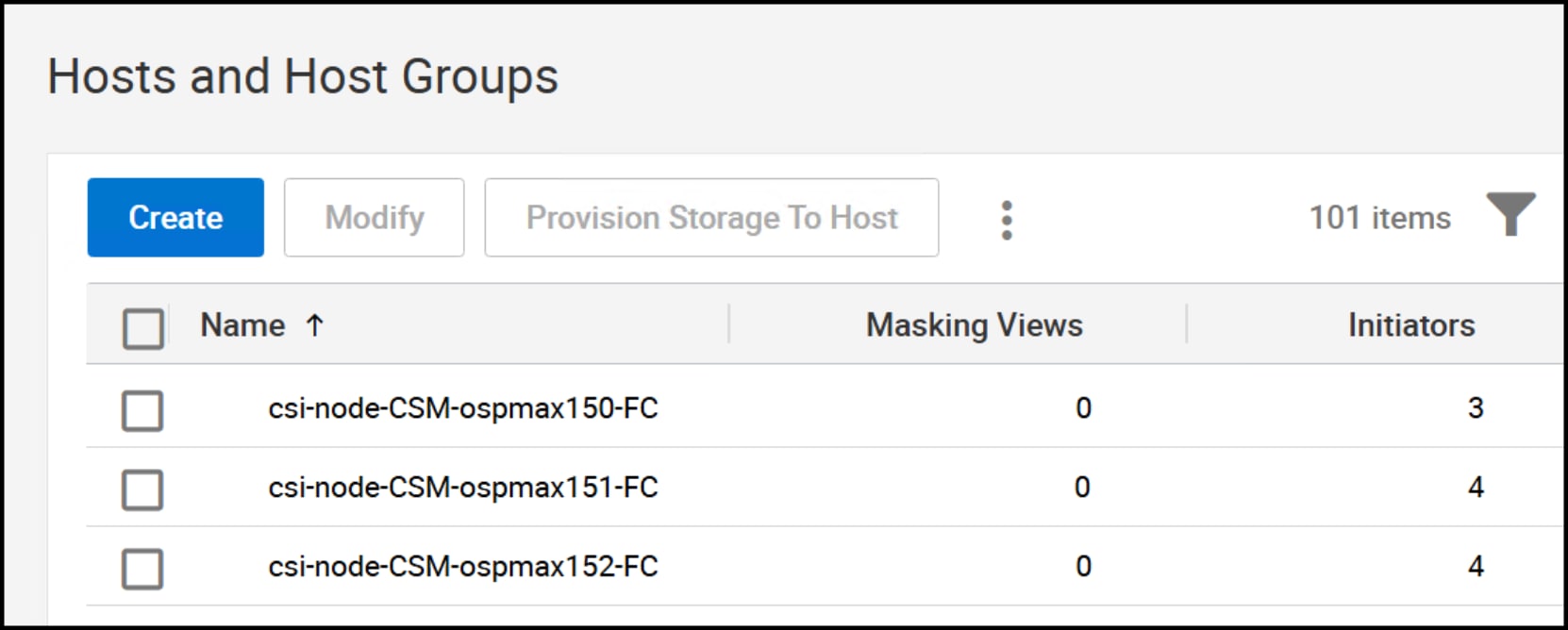
Figure 40. CSI-created host groups
Persistent volumes
A Persistent Volume (PV) represents a storage resource that you provision for use within a cluster. It abstracts the underlying storage system, allowing workloads to consume storage without managing implementation details. Unlike ephemeral volumes, a PV remains available after you delete pods, ensuring data persists across pod lifecycles. In this solution, Dell PowerMax serves as the persistent storage backend, delivering enterprise-grade performance and reliability for PVs.
StorageClass
A StorageClass defines the parameters and provisioner that Kubernetes uses to create PVs dynamically. When you create a PersistentVolumeClaim (PVC) and specify a StorageClass, Kubernetes provisions a PV that matches the class’s configuration—such as disk type, replication policy, or with Dell PowerMax, service level. By leveraging a StorageClass configured for Dell PowerMax, Kubernetes can automatically allocate high-performance, fault-tolerant storage resources, enabling dynamic, policy-driven storage allocation, and decoupling application requirements from physical infrastructure.
When you create an OpenShift Container Platform (OCP) cluster, the installer adds a storage class called localblock-sc for local block storage. The installer uses this class during deployment, but it does not set it as the default. Some resources—such as virtual machine OS distribution boot volumes—require a default storage class before the cluster can create them automatically. To meet this requirement, create a default storage class backed by Dell PowerMax.
You can create a default storage class through the CLI (oc or kubectl) or use the cluster console. We cover both below.
OpenShift Web Console
Step 1
Navigate to Storage -> StorageClasses in the left-hand menu. In the right-hand panel click on Create StorageClass. Only the installer-created storage class will be present.
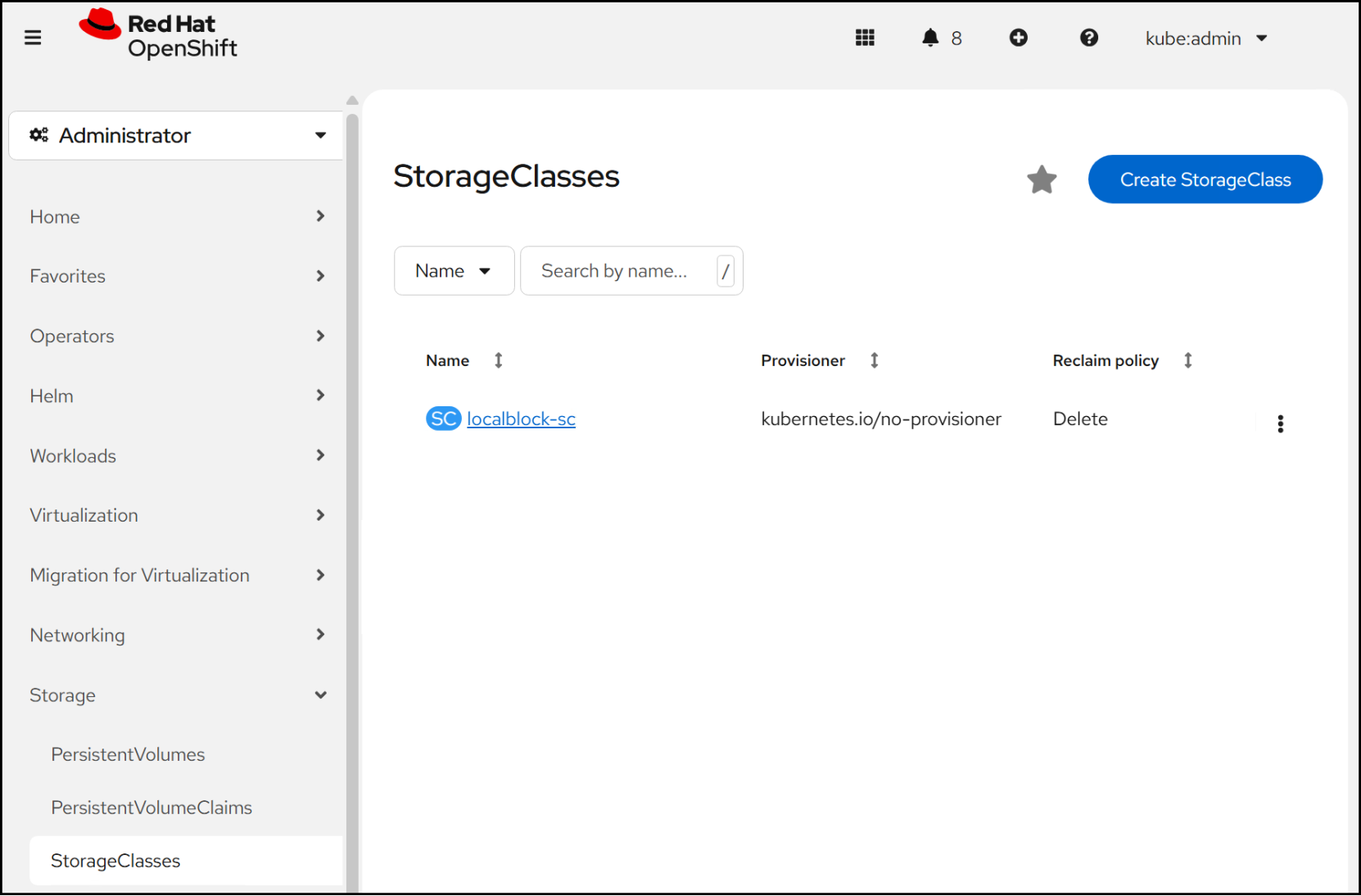
Figure 41. Step 1 – Default storage class
Step 2
Provide the necessary details for the storage class. Use the drop-down menu for the Provisioner to select csi-powermax.dellemc.com. You will have to add two parameters. One is for the PowerMax ID, SYMID, and the other is for the SRP. If you fail to include these, provisioning will fail. Optionally, you can add ServiceLevel. Leave the check box selected for expansion and click Create.
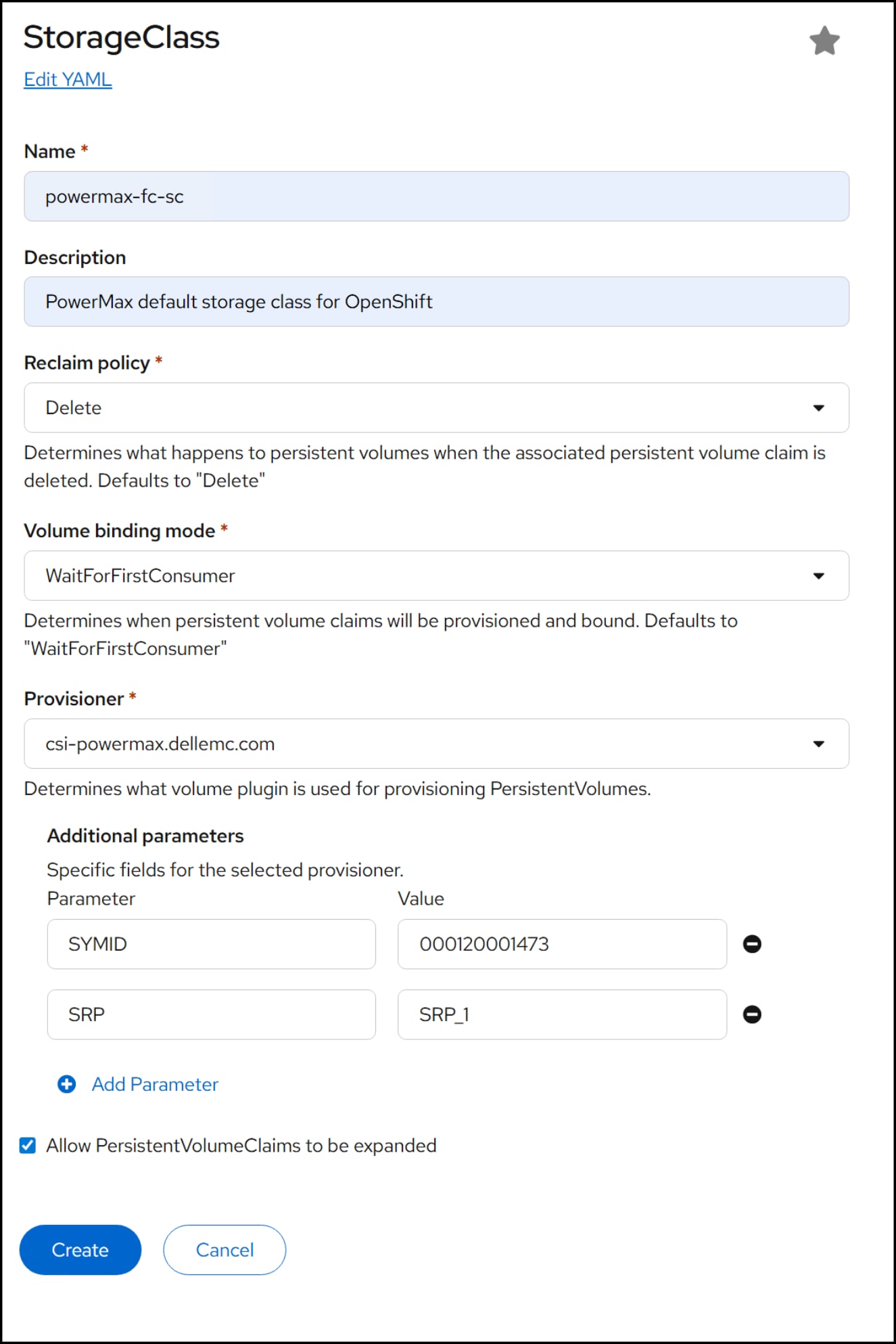
Figure 42. Step 2 – Default storage class
Step 3
To set the class as default, you must edit the storage class after creation. Click on the three buttons next to the new storage class and select Set as default.
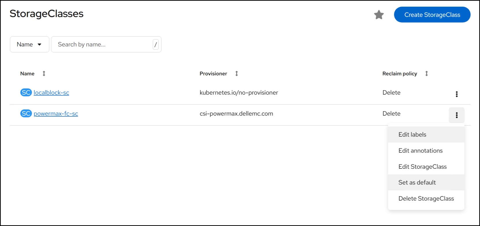
Figure 43. Step 3 – Default storage class
The storage class will now be set as default in Figure 44.
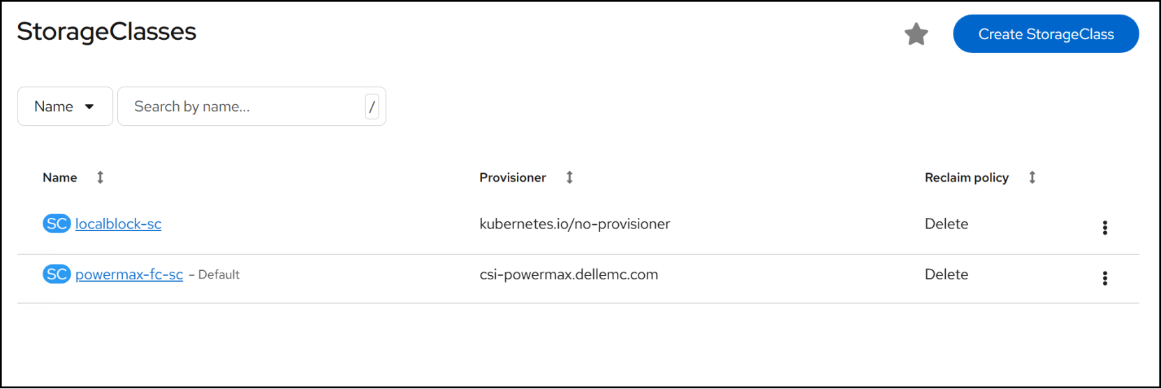
Figure 44. Complete – Default storage class
After you configure the default class, OpenShift provisions the boot volumes shown in the catalog and makes them available as templates for cloning when you deploy virtual machines.
Note: Do not create more than one default storage class. It can lead to undesirable results.
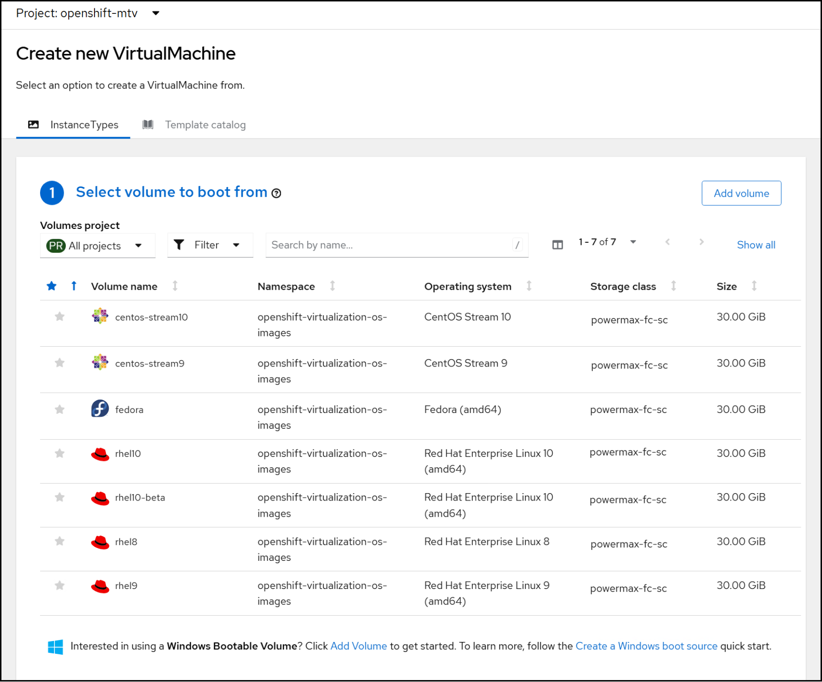
Figure 45. Linux OS boot volumes with PowerMax volumes
CLI via oc
If you prefer to use CLI, kubectl or oc, you can specify greater detail in the YAML file. For example, knowing OpenShift uses this storage class for Linux OS boot volumes, you may wish to set the service level from the default of Diamond to something less performant such as Bronze. To do this, construct the following YAML as follows, the creation output is in Figure 46.
apiVersion: storage.k8s.io/v1
kind: StorageClass
metadata:
name: powermax-fc-sc
annotations:
storageclass.kubernetes.io/is-default-class: "true"
parameters:
SRP: SRP_1
SYMID: "000120001672"
ServiceLevel: Bronze
csi.storage.k8s.io/fstype: xfs
provisioner: csi-powermax.dellemc.com
reclaimPolicy: Delete
volumeBindingMode: WaitForFirstConsumer
allowVolumeExpansion: true

Figure 46. Storage class via YAML
Deploying VMs and Containerized Applications
Introduction
Virtual Machines
You can use either CLI or the UI to deploy a VM. The UI also provides the ability to compose and execute a YAML directly. To create a VM using the UI follow these steps.
Step 1
In the left-hand menu of the UI (Figure 3), navigate to Virtualization -> VirtualMachines. In the right-hand panel use the drop-down menu for Create VirtualMachine and select From InstanceType.
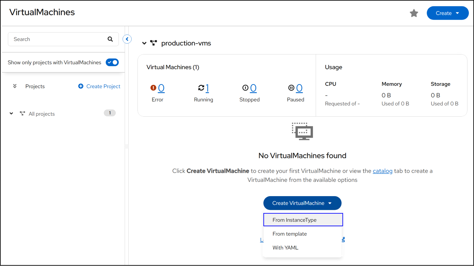
Figure 47. Step 1 – VM creation
Step 2
In the upper left-hand corner of the panel in Figure 48, you can adjust the Project from the Default. Here we set the project to production-vms. Select a boot volume such as rhel8. OpenShift will clone this volume for the new VM. Note as we covered previously, these volumes reside on Dell PowerMax.
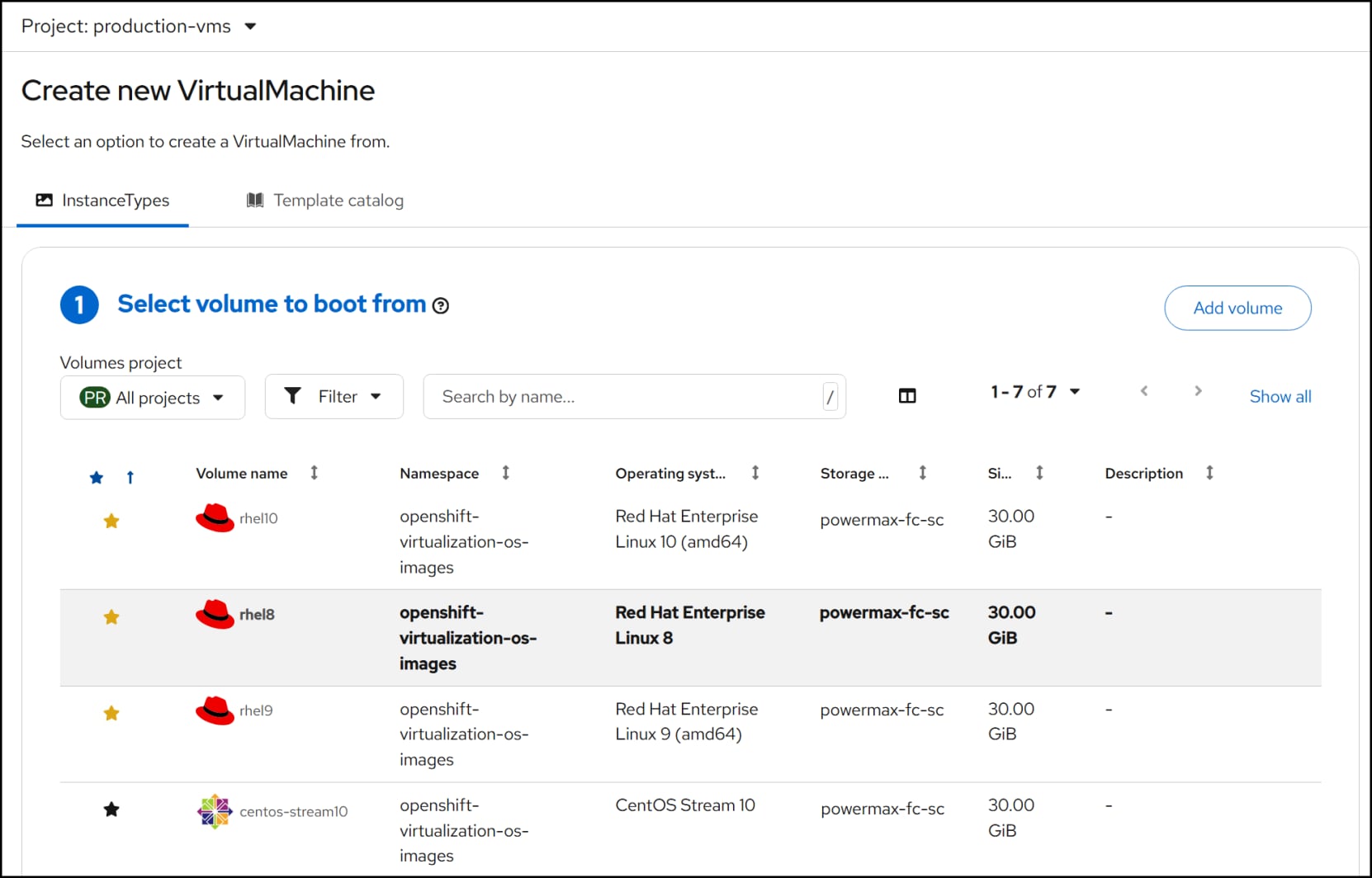
Figure 48. Step 2 – VM creation
Step 3
Scroll down the page and select an InstanceType that is either Red Hat or User provided. Here we select Red Hat provided General Purpose.
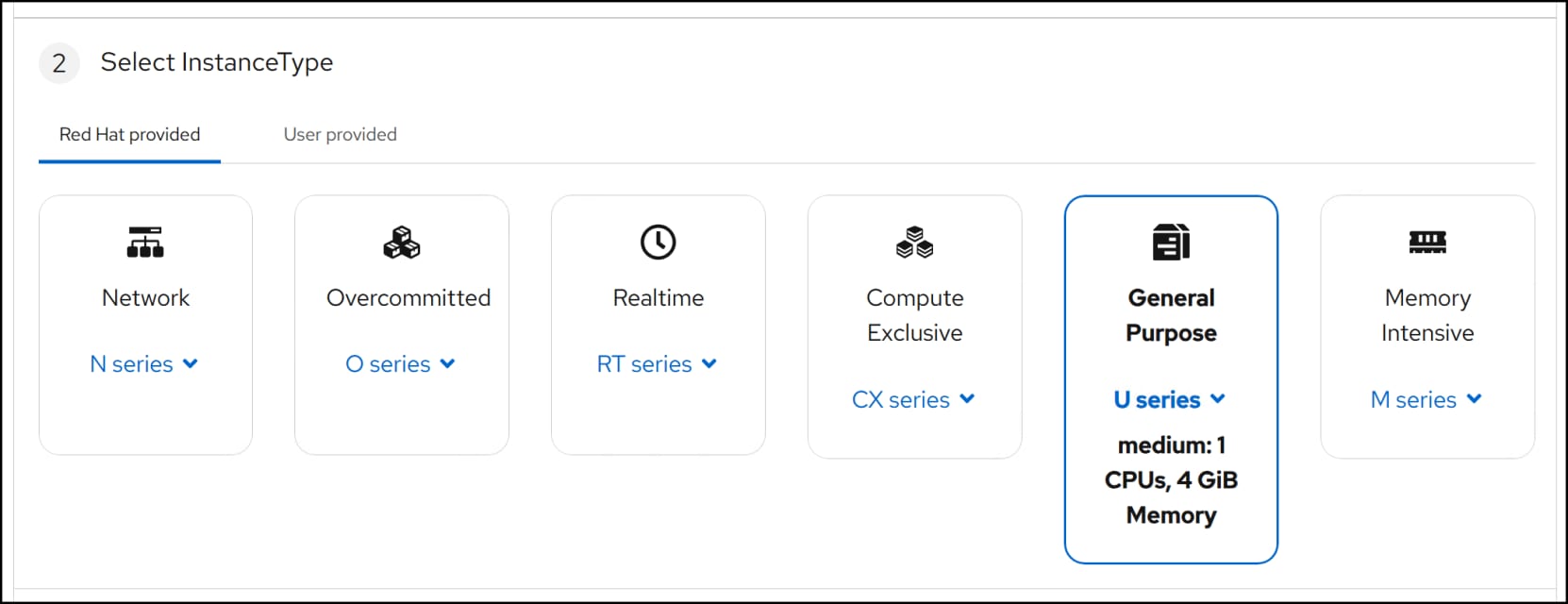
Figure 49. Step 3 – VM creation
Step 4
In the last section of the screen, make any adjustments to the VM such as Name or even Storage class. Since the creation clones the boot volume it does not have to retain the same storage characteristics. For example, the default powermax-fc-sc uses a Diamond service level, the most performant available. A boot volume does not require this level of performance so in this example we altered it to Bronze. Click Create VirtualMachine to complete the wizard.
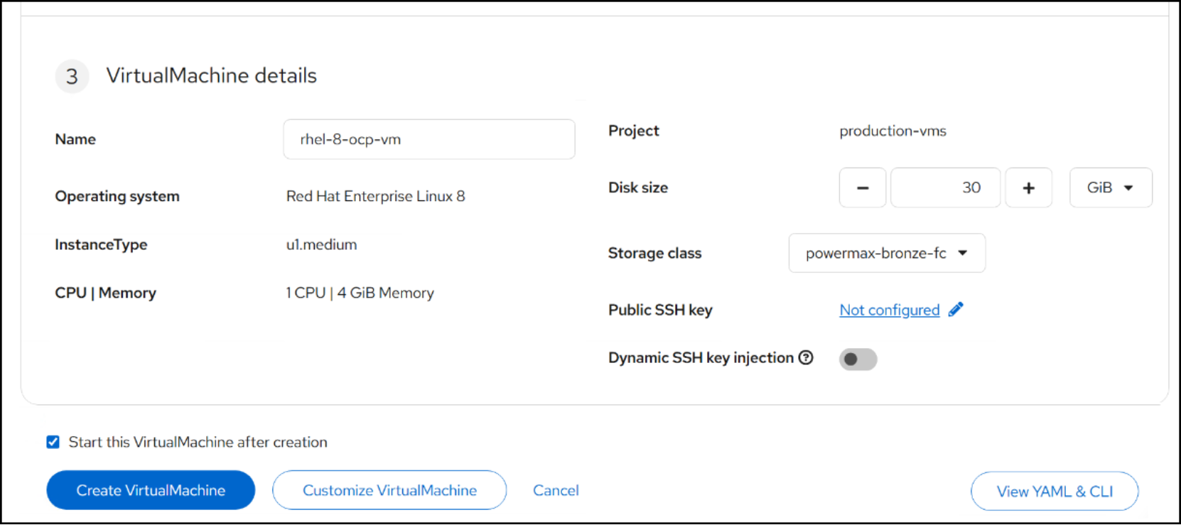
Figure 50. Step 4 – VM creation
Upon creation, OpenShift clones the image to a new volume with the Bronze service level.
ospmax170:~/.kube # kubectl get pvc -n production-vms
NAME STATUS VOLUME CAPACITY ACCESS MODES STORAGECLASS
rhel-8-ocp-vm-volume Bound csivol-0c475fd7f7 30Gi
RWX powermax-bronze-fc
ospmax170:~/.kube #
OpenShift offers a VNC console via the browser.
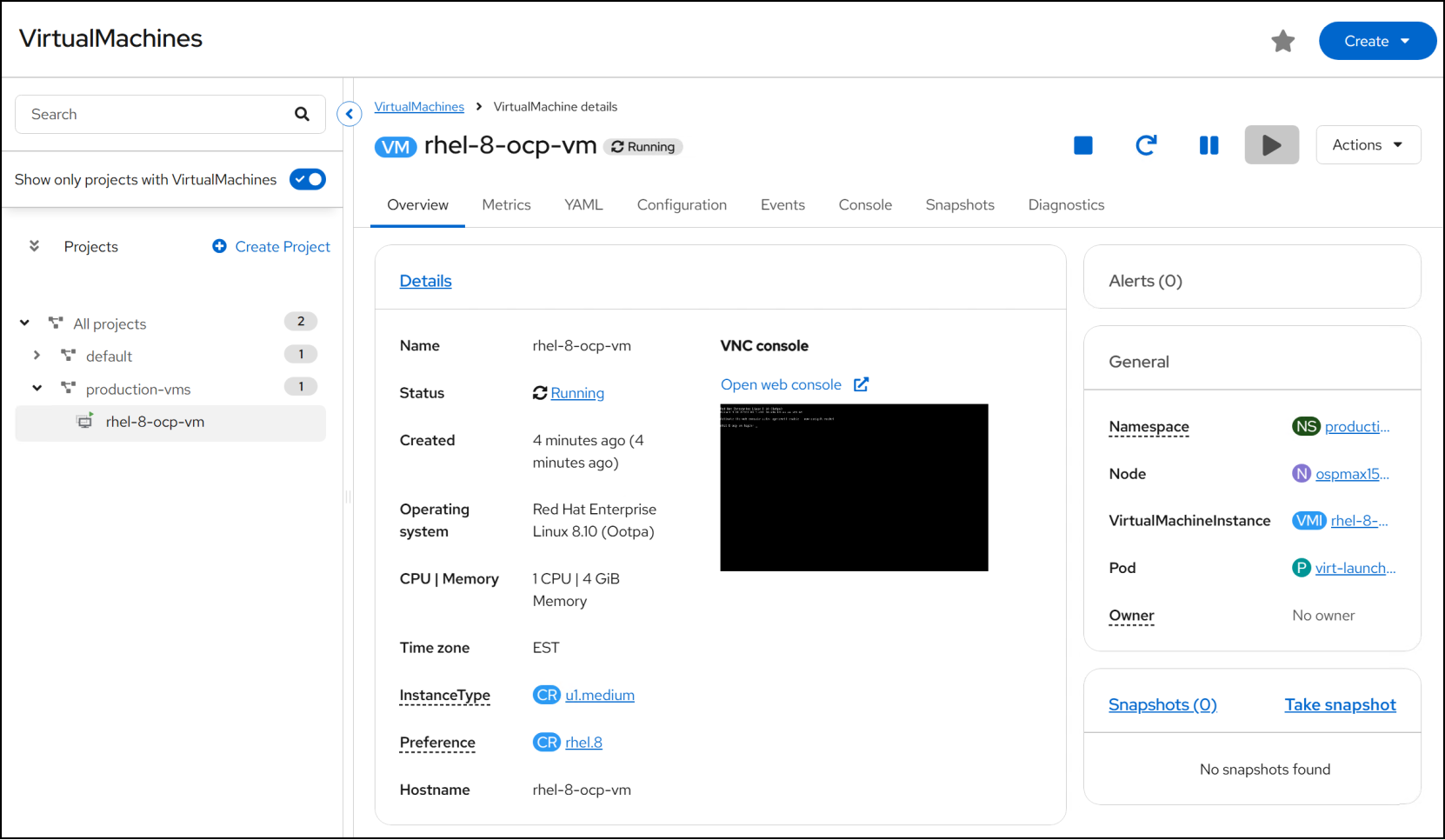
Figure 51. VM detail and VNC access
Snapshots
OpenShift offers VM-level snaps which are storage array snapshots driven through the CSI driver utilizing TimeFinder/SnapVX on the Dell PowerMax.
TimeFinder/SnapVX
TimeFinder/SnapVX, or SnapVX, is a local replication solution that creates point-in-time copies, or snapshots, of PowerMax devices. SnapVX creates snapshots by storing changed tracks (deltas) directly in the SRP of the source volume. With SnapVX, you do not need to specify a target volume and source/target pairs when you create a snapshot. If the application ever needs to use the point-in-time data, you can create links from the snapshot to one or more target volumes. If there are multiple snapshots and the application needs to find a particular point-in-time copy for host access, you can link and relink until the correct snapshot is located. Snapshots are crash-consistent copies of the data.
VM snapshot
You can execute a snapshot from a number of places in the UI or use the CLI. In Figure 51 you can use the Actions menu and select Take snapshot or use the hyperlink in the bottom right-hand corner.
The CSI driver acts as a bridge between the Kubernetes cluster and the storage array. When you create a VolumeSnapshot, the CSI driver sends a request to the storage array to create a snapshot of the PV. The storage array then creates the snapshot and returns a unique identifier to the CSI driver, which stores this identifier in the Kubernetes VolumeSnapshot object.
You can query the snapshot through CLI or Unisphere for PowerMax. You can reconcile the two by viewing the SNAPSHOTCONTENT field in CLI and matching it against the snapshot name in the UI.
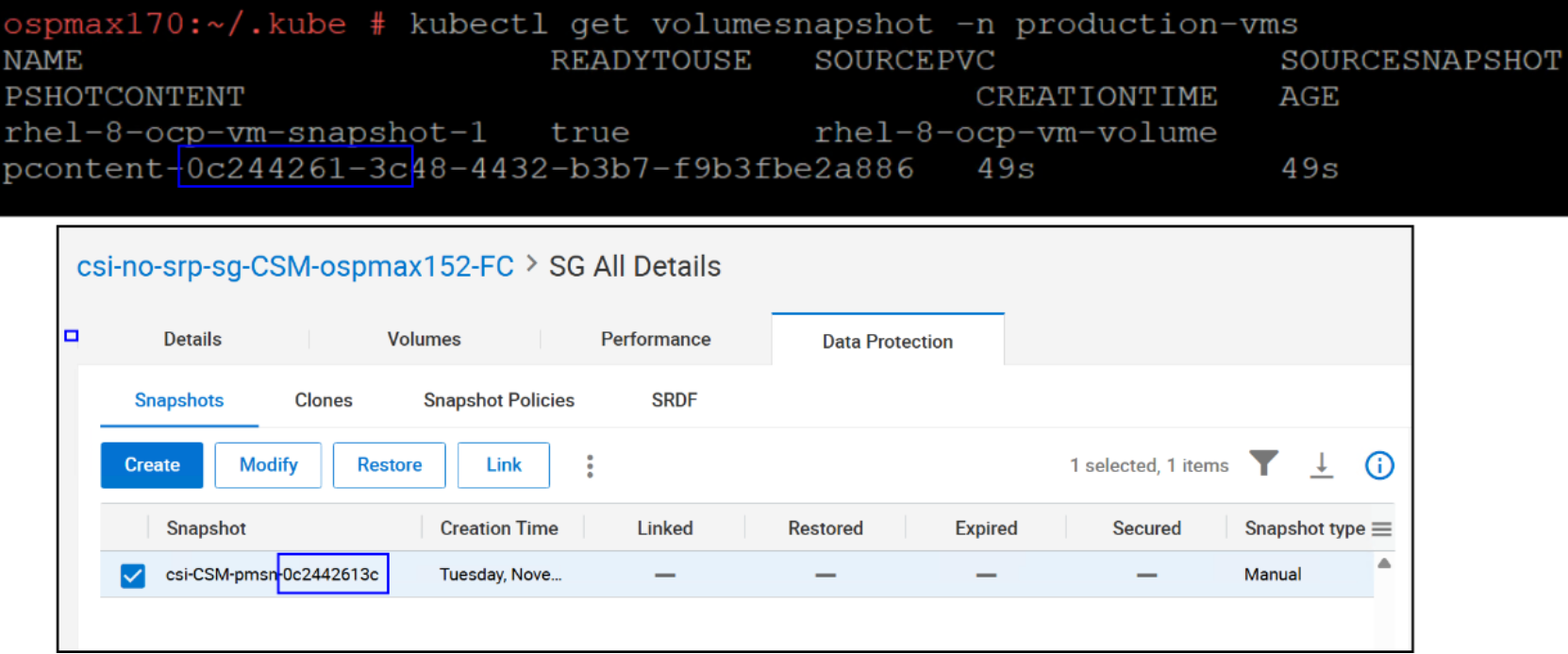
Figure 52. VM snapshot reconciliation in CLI and UI
External networks
If you need to access a virtual machine (VM) from outside the OpenShift cluster, you have several options with varying complexity. The most effective approach is to use an additional NIC on the OpenShift node for VM traffic. To do this, identify the extra physical interface, ensure it is active, and confirm it is available. Then create a NetworkAttachmentDefinition (using Multus) that references this interface, typically through a bridged connection. Alternatively, you can create a secondary Open vSwitch (OVS) bridge bound to the NIC. When you define the VM or pod, attach it to this network so it can obtain an IP address from your physical network via DHCP or static assignment. Verify that firewalls, VLANs, and network policies allow the intended traffic. This configuration isolates VM traffic on the extra NIC while keeping OpenShift management and default pod networks separate.
Note: Red Hat does not recommend utilizing the cluster network devices for external access.
This procedure executes commands directly on the OCP nodes. Red Hat recommends using a MachineConfig file rather than accessing the nodes. If you prefer that model, there is an example in the Adding a VM bridged network section of the Appendix.
Adding a bridged network
To create the bridge and slave, ssh into your node as the “core” user from a box configured for this purpose. In this simple example, I am using one NIC, eno3, which is up and not part of the OpenShift environment. The names of the bridge and slave are arbitrary.
Step 1
Delete any existing profiles for the NIC in question. In this example I am using eno3.
sudo nmcli connection delete br-eno3
sudo nmcli connection delete bridge-slave-eno3
Step 2
Create the bridge. Since we intend this network for use by the VMs, we do not assign an IP to it.
sudo nmcli connection add type bridge ifname br-eno3 con-name br-eno3 ipv4.method disabled ipv6.method ignore
Step 3
Add eno3 as the slave to the master bridge.
sudo nmcli connection add type ethernet ifname eno3 con-name bridge-slave-eno3 master br-eno3
Step 4
Finally set the interfaces to auto-connect on reboot and bring them up.
sudo nmcli connection modify br-eno3 connection.autoconnect yes
sudo nmcli connection modify bridge-slave-eno3 connection.autoconnect yes
sudo nmcli connection up br-eno3
sudo nmcli connection up bridge-slave-eno3
Once complete, exit the session.
VM network
To enable the VM to use the new network, use Multus to configure a NetworkAttachmentDefinition (NAD). Multus is a CNI plugin for Kubernetes that enables attaching multiple network interfaces to pods. By default, Kubernetes only supports one network interface per pod. A NetworkAttachmentDefinition (NAD) is a Kubernetes custom resource (CRD) that defines how a pod should connect to an additional network.
In this environment, we created the following NAD which permits assigning the network to multiple VMs.
apiVersion: k8s.cni.cncf.io/v1
kind: NetworkAttachmentDefinition
metadata:
name: br-eno3-network
namespace: production-vms
annotations:
kubevirt.io/network-binding: bridge
k8s.v1.cni.cncf.io/resourceName: bridge.network.kubevirt.io/br-eno3
spec:
config: |
{
"cniVersion": "0.3.1",
"type": "bridge",
"bridge": "br-eno3",
"isGateway": true
}
When you create a VM or attach a network adapter to an existing one, you can specify the bridged network as in Figure 53.
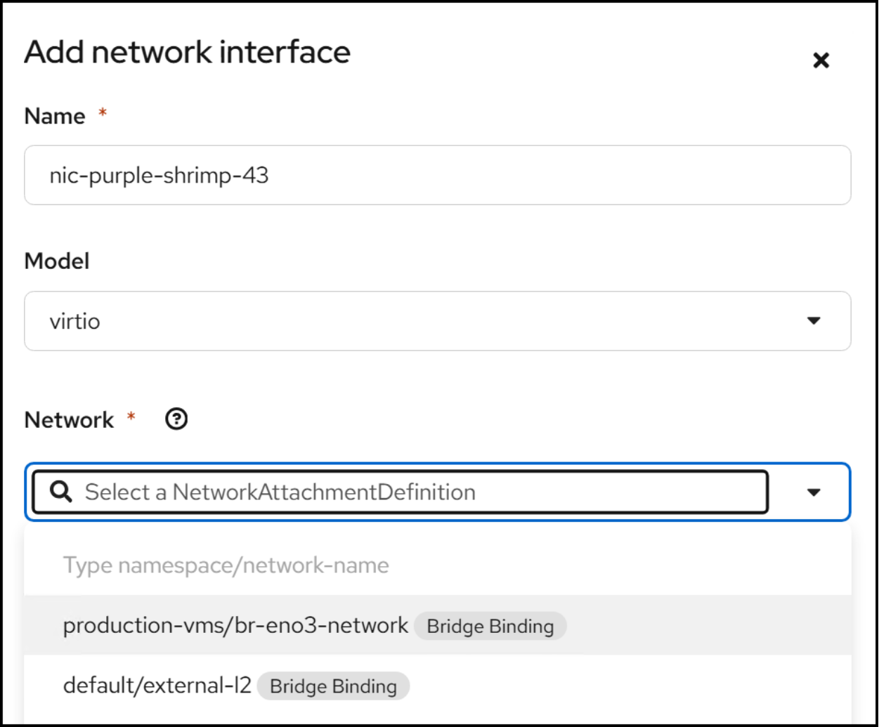
Figure 53. Adding bridged network to VM
Containerized applications
You can deploy applications on OCP using the web console or CLI. The UI offers a software catalog of common applications, services, and templates. Since many of these catalog items use a DeploymentConfig rather than a Deployment, be aware that Red Hat deprecated the DeploymentConfig object in OpenShift version 4.14.

Figure 54. DeploymentConfig deprecation
Because Red Hat continues to publish the catalog items, the next section will demonstrate both a deploymentconfig and deployment of the same database, MySQL.
DeploymentConfig
Create a MySQL deploymentconfig by following these steps.
Step 1
Login to the web console and navigate in the UI to Home -> Software Catalog in the left-hand menu. In the right-hand panel select All items -> Databases -> MySQL. Click on the first template which requires persistent storage.
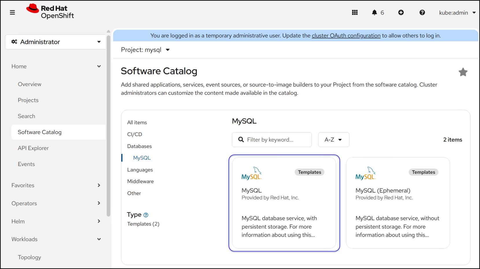
Figure 55. Step 1 – MySQL deploymentconfig
Step 2
Next click on Instantiate Template to open the entry form.
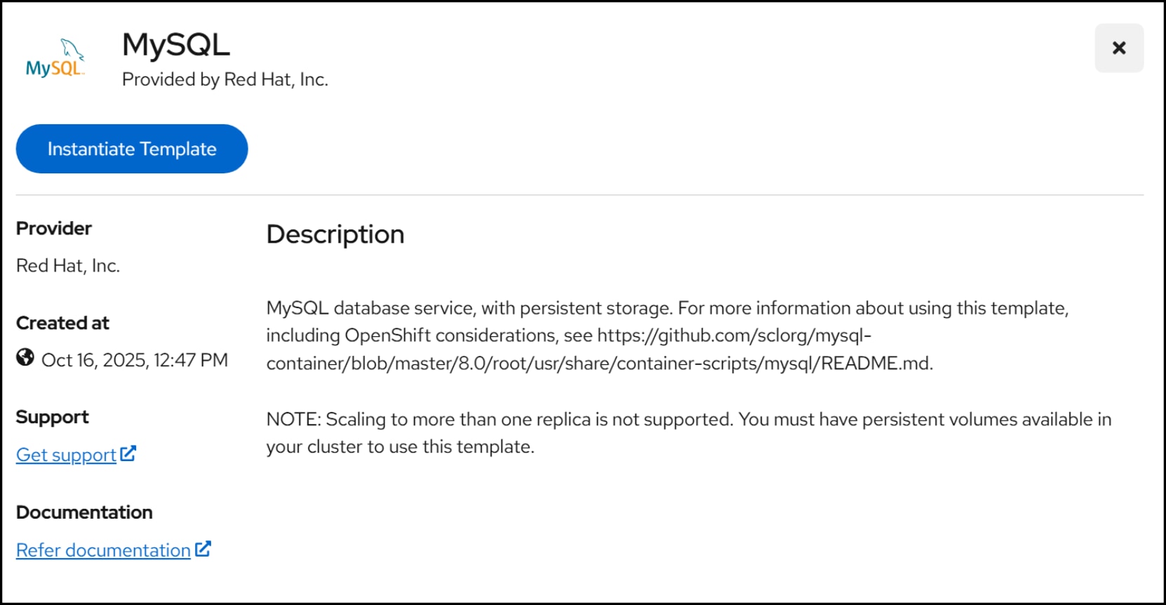
Figure 56. Step 2 – MySQL deploymentconfig
Step 3
The template does not require any changes if you are taking the defaults. In this example below, however, we adjusted the namespace to mysql and updated the volume capacity from 1 to 10 Gi. Since this template uses persistent storage, it is essential you have a default storage class for the Dell PowerMax. Click Create to complete the template and deploy MySQL.
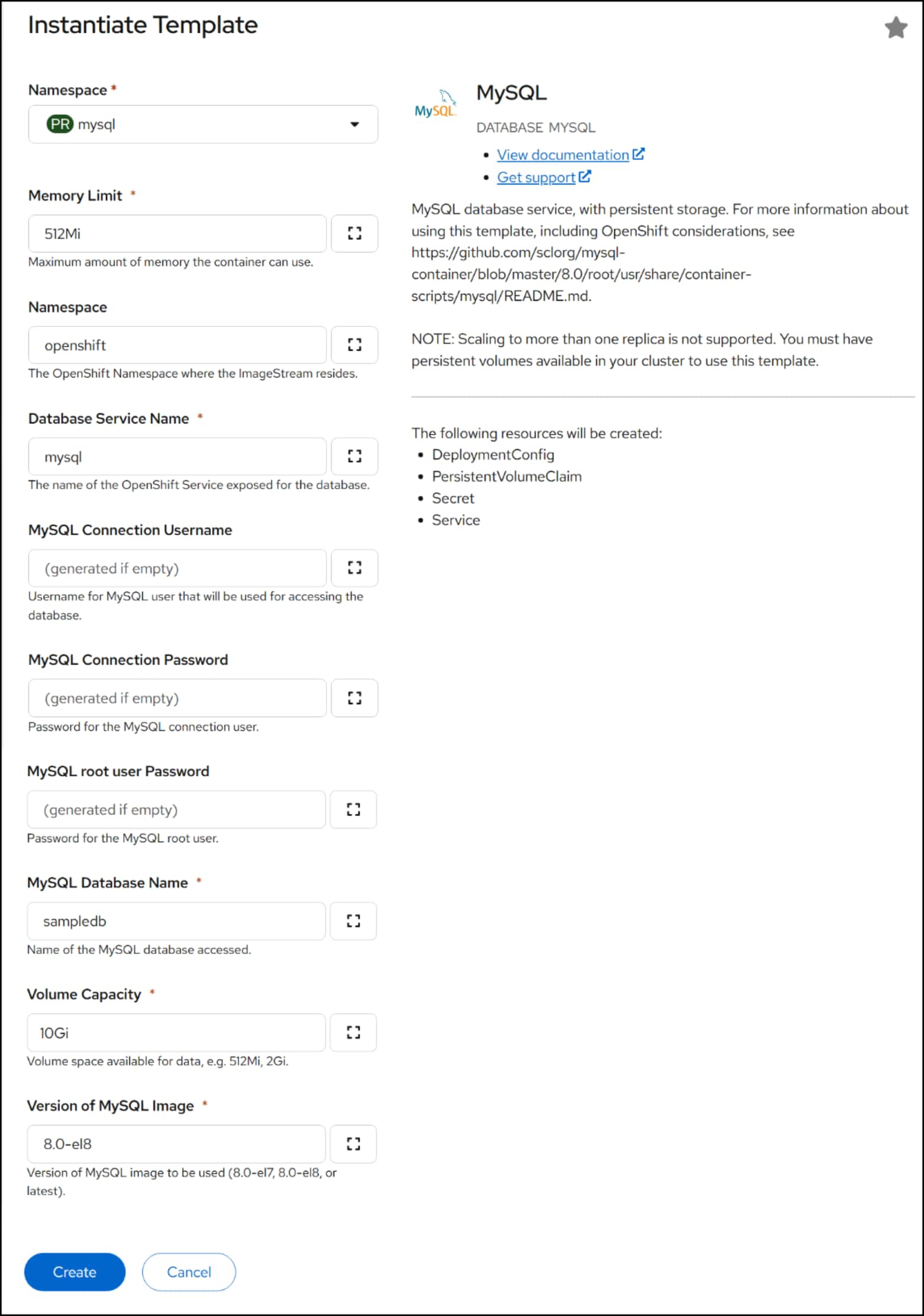
Figure 57. Step 3 – MySQL deploymentconfig
You can access the new deployment through the left-hand menu Workloads -> DeploymentConfigs and then in the right-hand panel select your project. The UI offers direct access to the MySQL pod through a terminal, if desired.
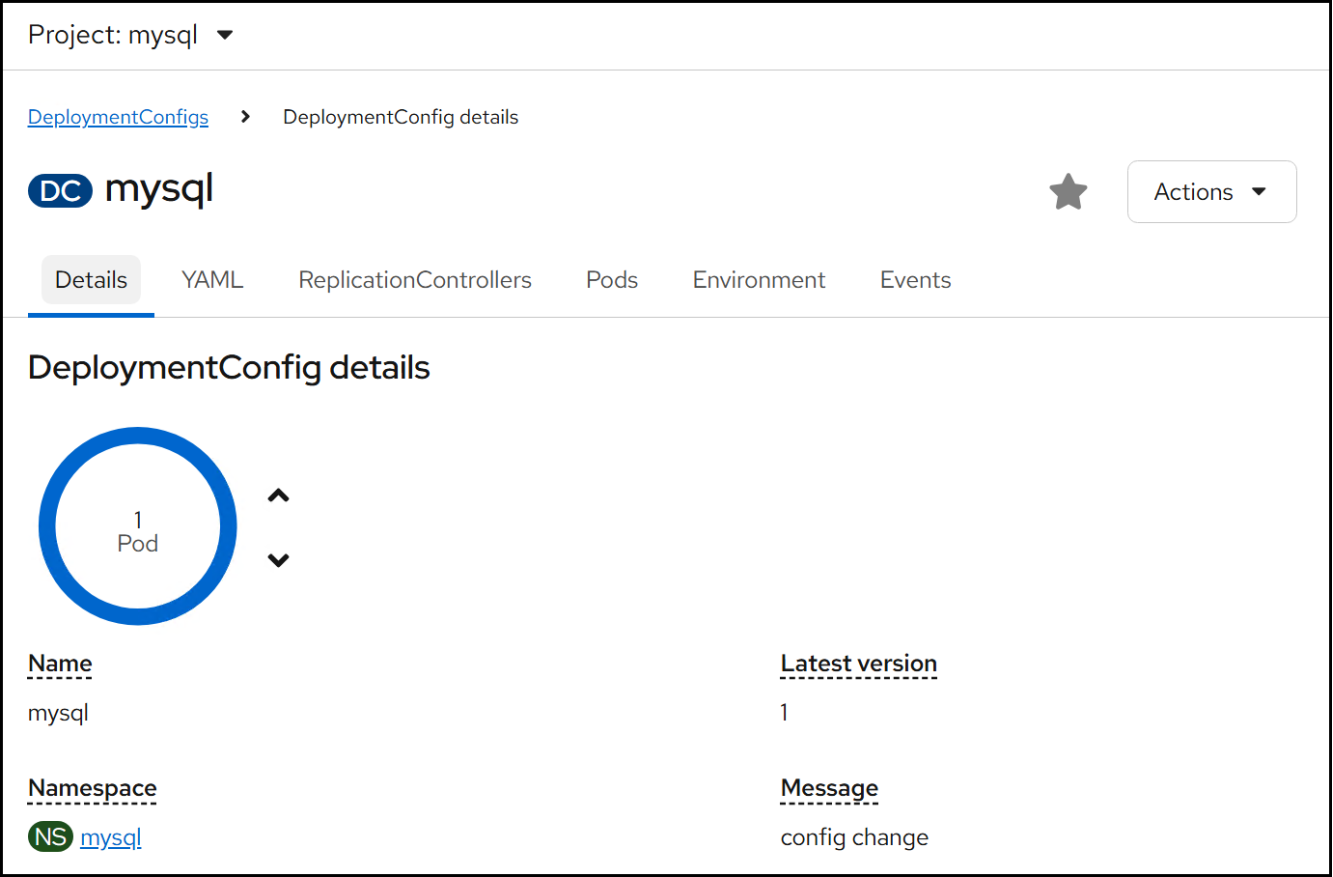
Figure 58. MySQL deploymentconfig
Here you can see the PowerMax 10 GB persistent storage for the pod, using the default storage class powermax-fc-sc.
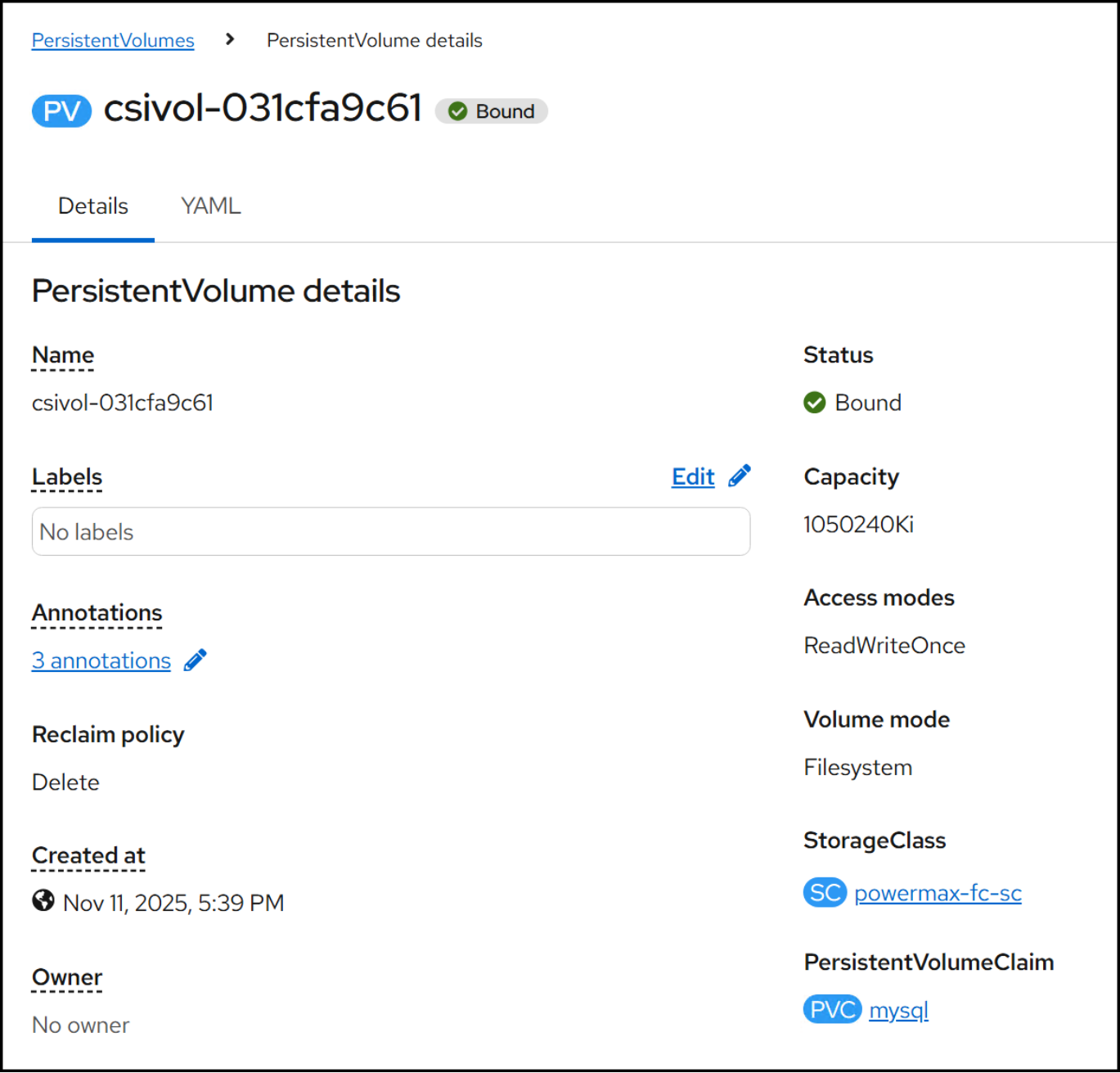
Figure 59. PowerMax persistent storage for MySQL deploymentconfig
Deployment
Unlike the deploymentconfig which creates all objects as part of the template, a deployment of the same MySQL database entails creating the storage, deployment, and service separately. Create a MySQL deployment by following these steps.
Step 1
Login to the web console and navigate in the UI to Storage -> PersistentVolumeClaims in the left-hand menu. In the right-hand panel click Create PersistentVolumeClaim. In the YAML form enter in the required information. Note here we are using the storage class powermax-bronze-fc since this is a test environment and does not require high performance. Click Create to complete.
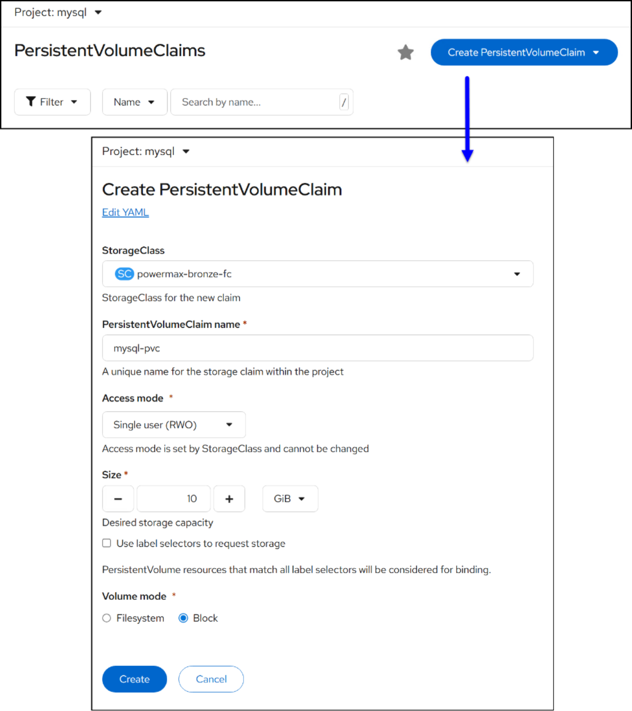
Figure 60. Step 1 – MySQL deployment
Step 2
Next navigate to Workloads -> Deployment in the left-hand menu. In the right-hand panel click Create Deployment. In the Create Deployment wizard, choose the view, Form or YAML, and enter the required information. Be sure to reference the PVC you created in step 1. Click Create to complete.
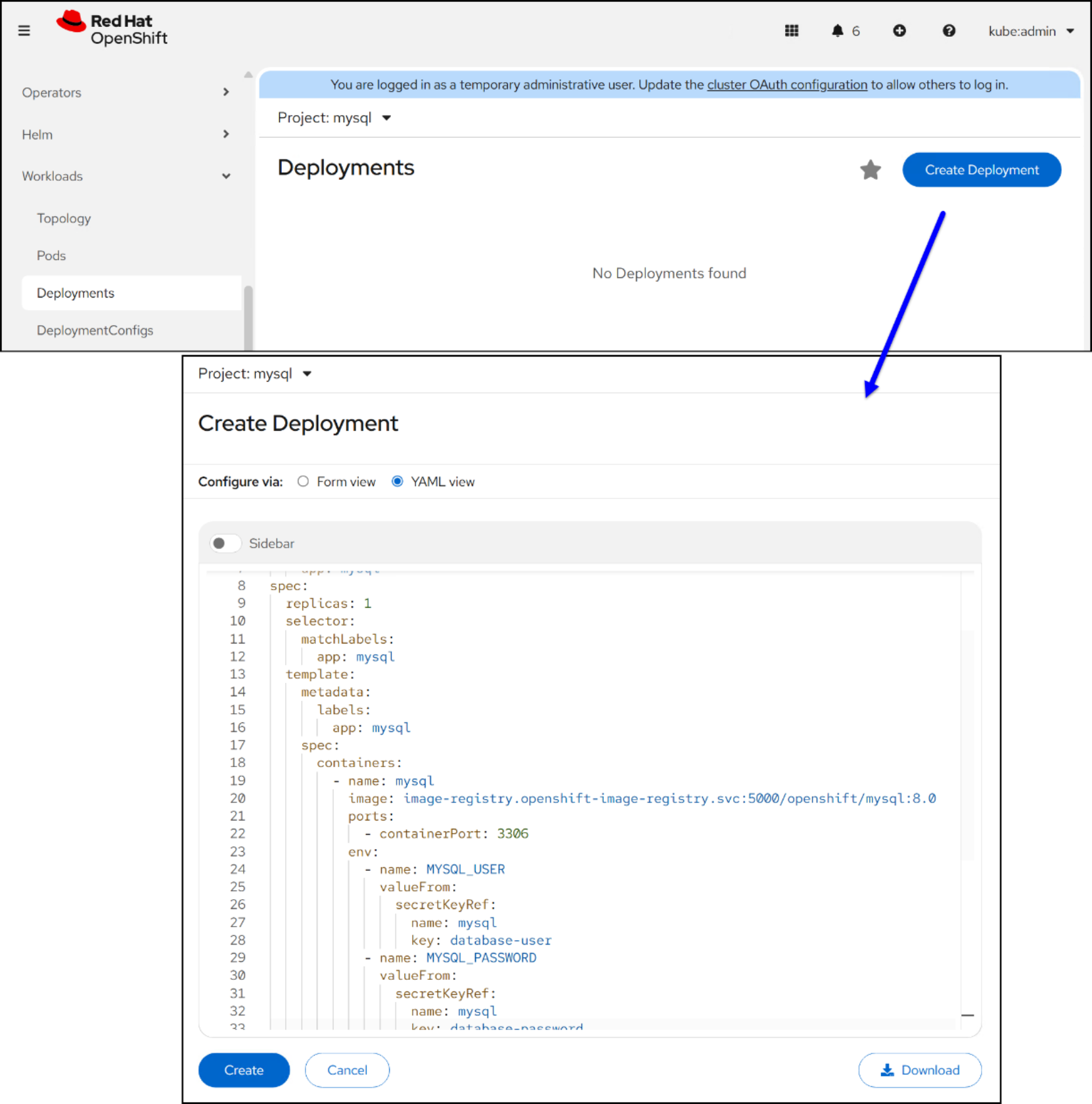
Figure 61. Step 2 – MySQL deployment
Step 3
Finally, create the service. Navigate to Network -> Services. In the right-hand panel click Create Service. Enter the required information and click Create.
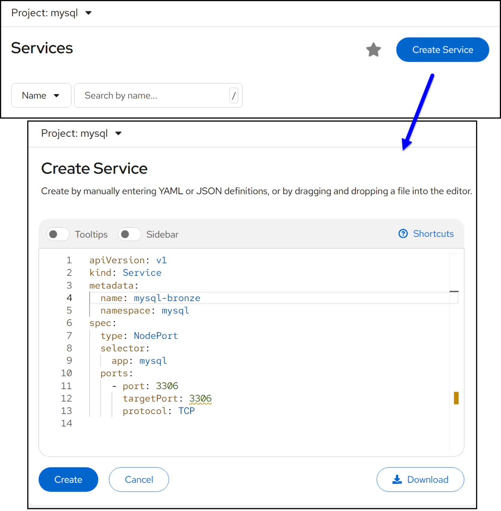
Figure 62. Step 3 – MySQL deployment
The new deployment is complete.
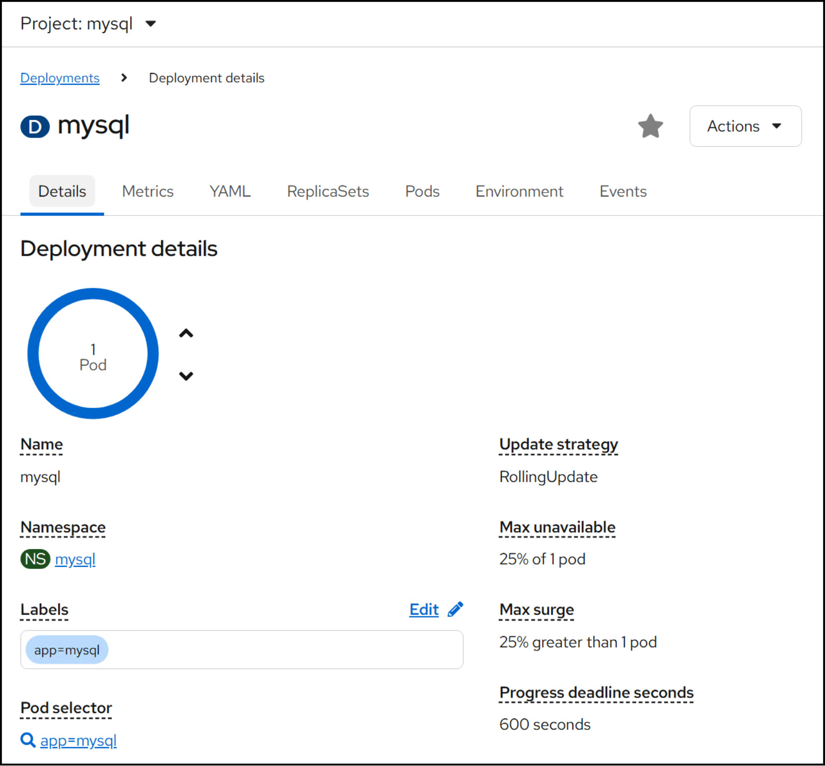
Figure 63. MySQL deployment
Migration
Introduction
Migration Toolkit for Virtualization
The Migration Toolkit for Virtualization, or MTV, provides a comprehensive solution for moving existing virtual machines from platforms such as VMware vSphere, Red Hat Virtualization and OpenStack into a modern container-based environment powered by Red Hat OpenShift Virtualization. It enables the planning, migration, and management of VM workloads to run natively within OpenShift, helping organizations accelerate cloud-native adoption, reduce operational complexity, and modernize infrastructure. By supporting cold, warm, and live migration workflows, and by providing mapping tools for storage, network and compute resources, the toolkit offers flexibility for on-premises and hybrid cloud scenarios.
MTV is an installed Operator. It supports a number of providers from which you can migrate in Figure 64. There are three modes of migration:
- Cold – Powered off VMs. It does not require common storage. It supports all providers.
- Warm – Powered on VMs. It does not require common storage but only supports VMware vSphere and Red Hat Virtualization providers.
- Live – Powered on VMs. It requires common storage, and it only supports OpenShift Virtualization clusters or migration within the same cluster across namespaces.
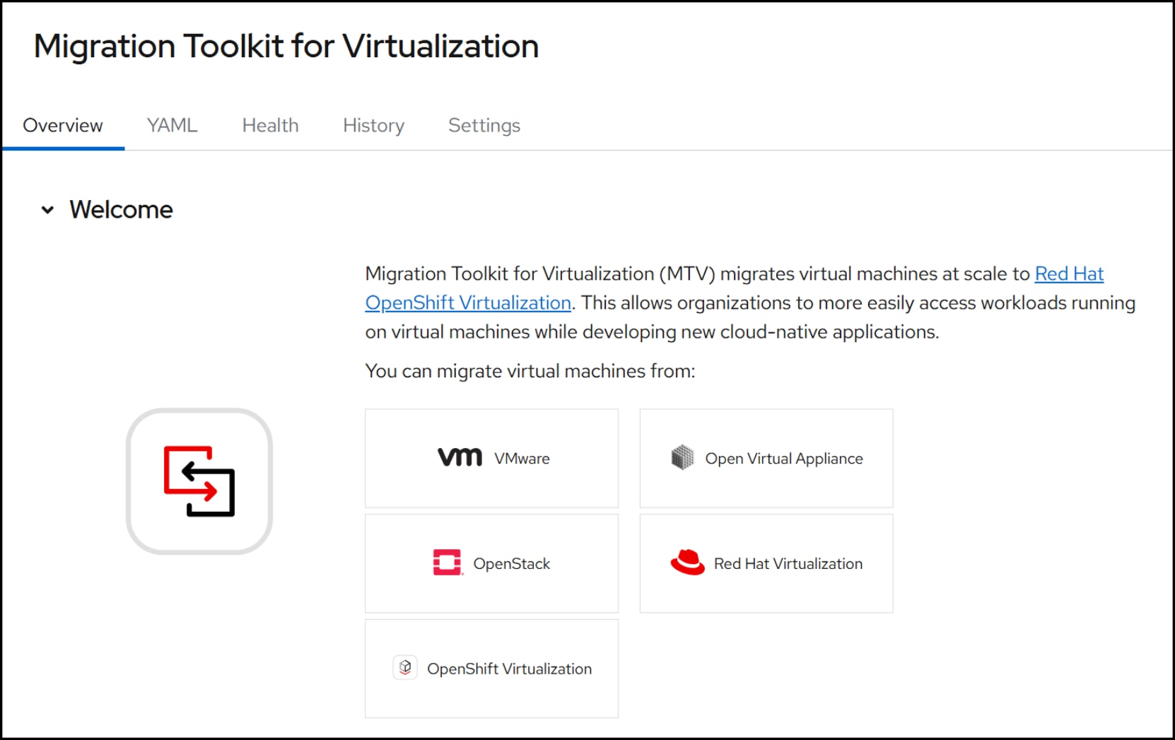
Figure 64. Migration Toolkit for Virtualization
For cold and warm modes, MTV performs network-based migrations, transferring virtual machine data and configurations from the source hypervisor to OpenShift Virtualization over the network. MTV copies disk images and metadata through managed data transfer channels, ensuring that it recreates virtual machines accurately in the target OpenShift cluster.
VM Migration
In the following sections, we walk through migrating a virtual machine from VMware vSphere to OCP using MTV. This includes configuring the VMware vSphere provider.
Provider
Create a VMware vSphere provider.
Step 1
Login to the UI and navigate to Migration for Virtualization -> Providers in the left-hand menu. In the right-hand panel click the VMware box which is a link to a form.
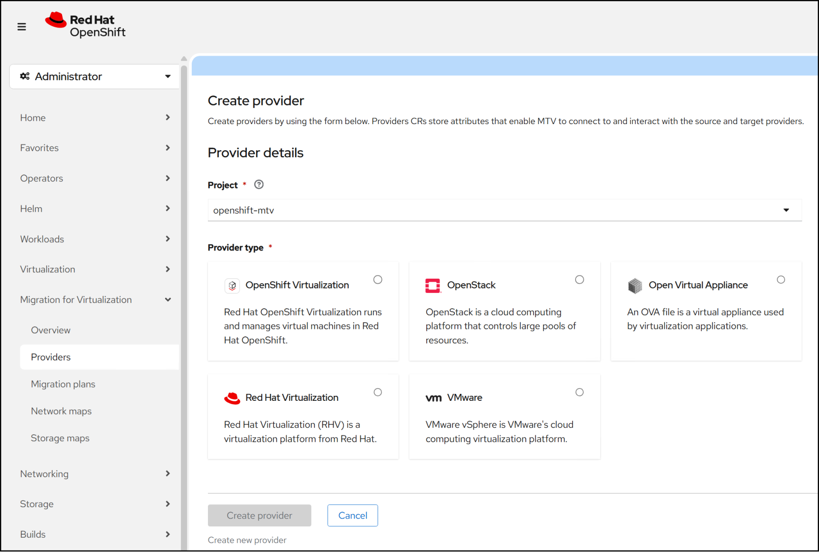
Figure 65. Step 1 – VMware provider
Step 2
Fill out the mandatory information in Figure 66 as follows:
- Choose a Project – it will default to openshift-mtv.
- Provider type leave at VMware default.
- Enter a Provider resource name.
- Use the radio buttons to select an Endpoint type.
- Enter the URL for the API endpoint.
- Input the VDDK init image or use the VDDK init image archive to build a new one. Follow the hyperlink if necessary to learn how.
- Dell recommends checking the box for VDDK async IO Optimization. This only impacts cold migrations.
- Enter the Provider credentials for either ESXi or vCenter, depending on the endpoint.
- Username
- Password
- Finally, either Skip certificate validation or supply the CA certificate.
Click Create provider to complete.
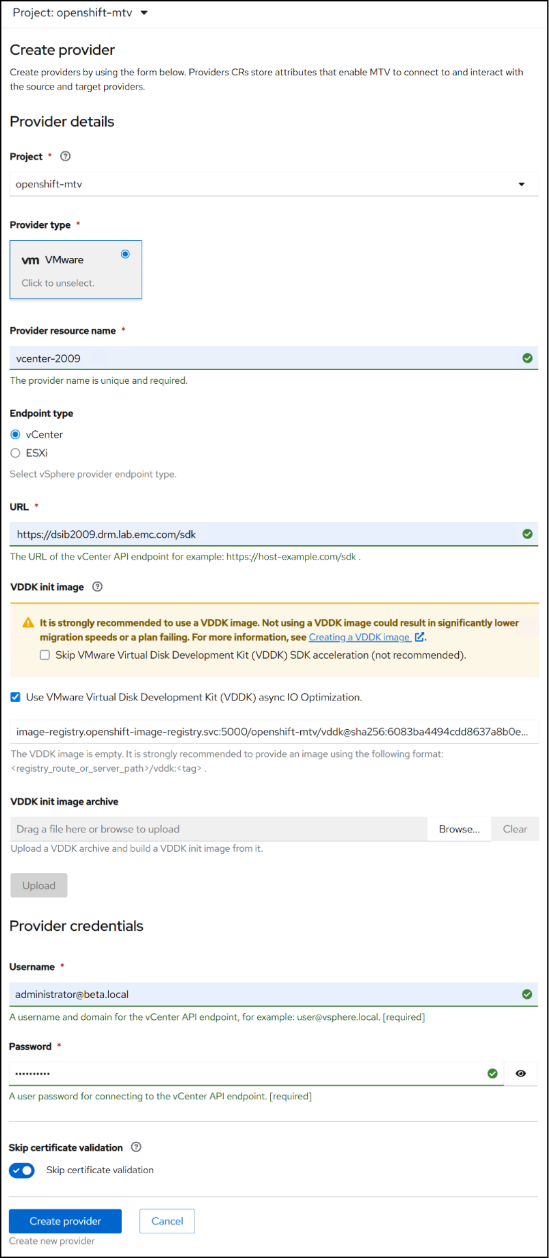
Figure 66. Step 2 – VMware provider
You can view the VMware provider source under Migration for Virtualization -> Providers. Upon creation of the provider, OpenShift inventories the vCenter or ESXi host. In Figure 67, the provider shows twenty-one VMs, seven networks, and two hosts in vcenter-2009. You can now migrate these VMs, provided they meet the necessary criteria.
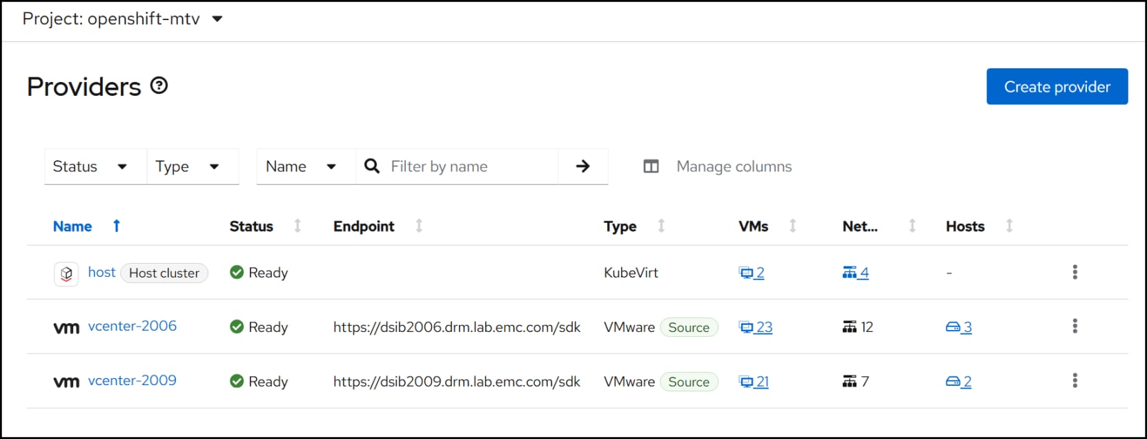
Figure 67. Migration providers
VM migration
To migrate a VMware VM to your OpenShift cluster follow these steps. This is a cold migration which takes advantage of the async IO Optimization. Note that the vmdk disk type is not relevant. The migration copies the data, whether thin, thick, or zeroedthick.
Step 1
Login to the UI (Figure 65) and navigate to Migration for Virtualization -> Migration plans in the left-hand menu. In the right-hand panel click Create plan.
Step 2
In the next step input the following information.
- Plan name
- Plan project
- Source provider (previously created)
- Target provider (host or OCP)
- Target project
Click Next.
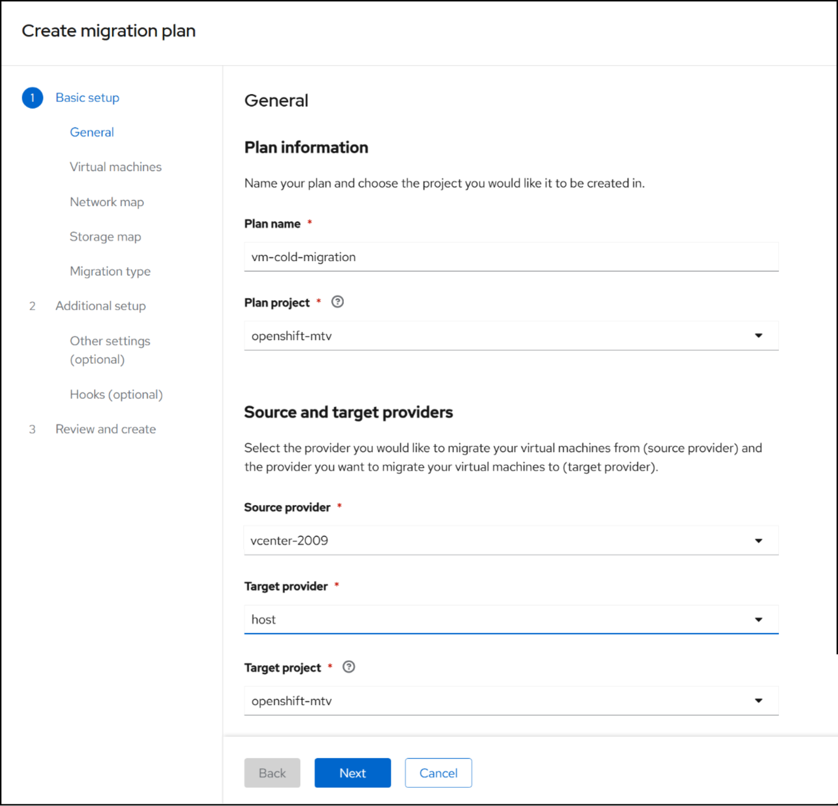
Figure 68. Step 2 – Migration plan
Step 3
The wizard now presents all the VMs from the source. Choose one or more VMs using the checkboxes. OpenShift will list any critical, warning, or information concerns for the VM. In the example in Figure 69, the wizard lists two warning concerns and one informational. The first warning is about CBT, which only impacts warm migrations. The second is self-explanatory about static IPs. Finally, the information warning simply states that the VMware feature DRS is not a feature on OpenShift. Click Next to continue.
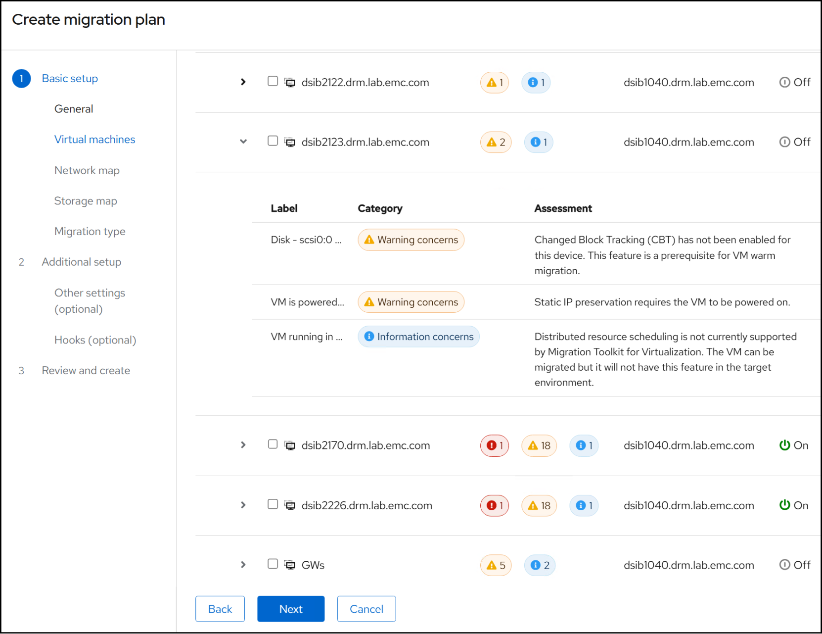
Figure 69. Step 3 – Migration plan
Step 4
Next, you need to map the VM networks to the OCP cluster networks. In this example in Figure 70, we map the VM network to the default network. If you setup external networks, as covered in Adding a bridged network, you can choose that from the drop-down menu. You can name the network map or allow it to default as here. Click Next.
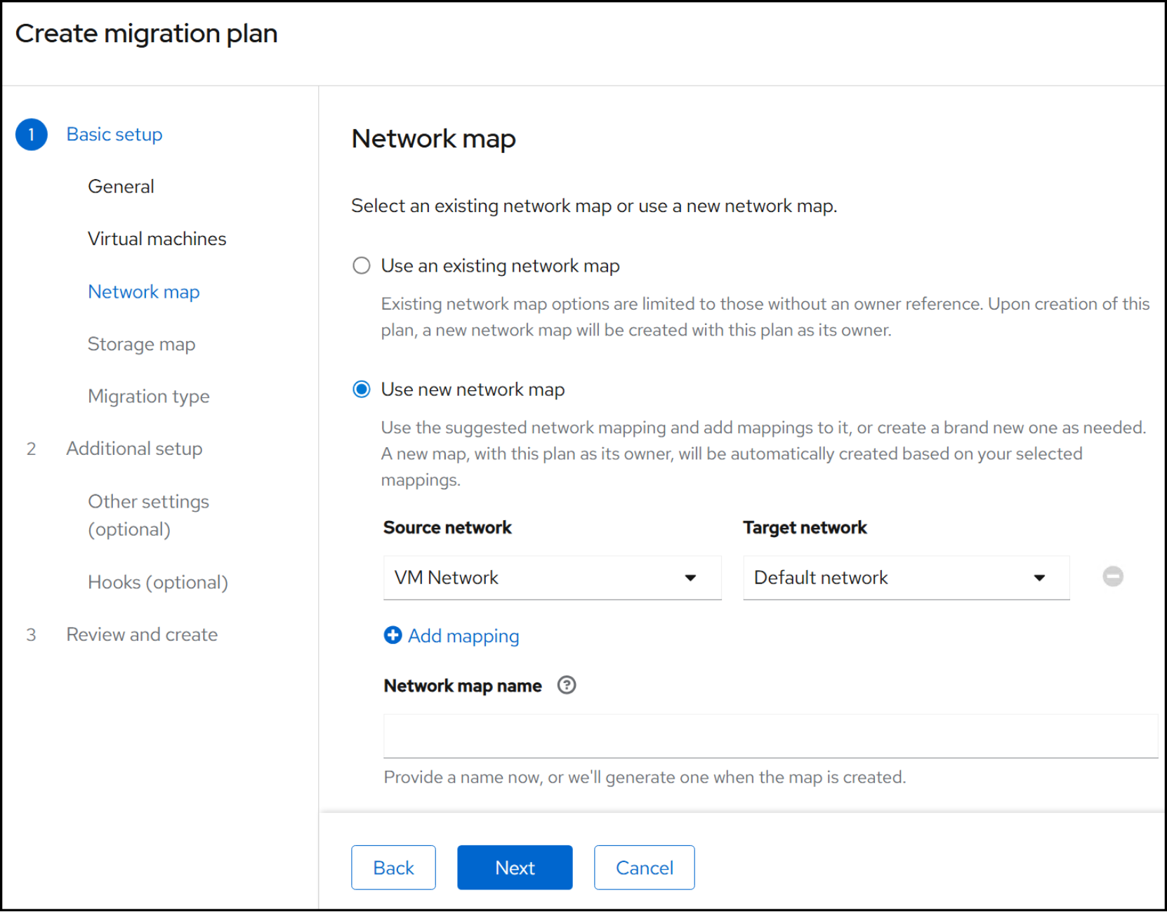
Figure 70. Step 4 – Migration plan
Step 5
In this step, map the VMFS datastore to a target storage class. If the VM vmdks reside in more than one datastore, you will need to provide a storage class for each mapping. In this example below, as we are doing a migration within the PowerMax array, we choose a storage class for the same array as the datastore. You can name the storage map or allow it to default as here Click Next.
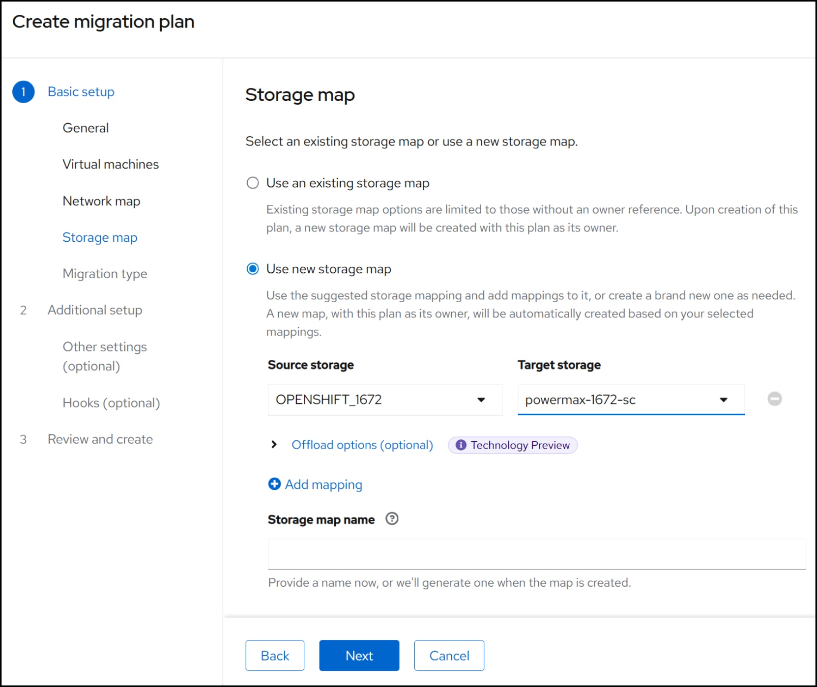
Figure 71. Step 5 – Migration plan
Step 6
Select the migration type, cold or warm, and click Next.
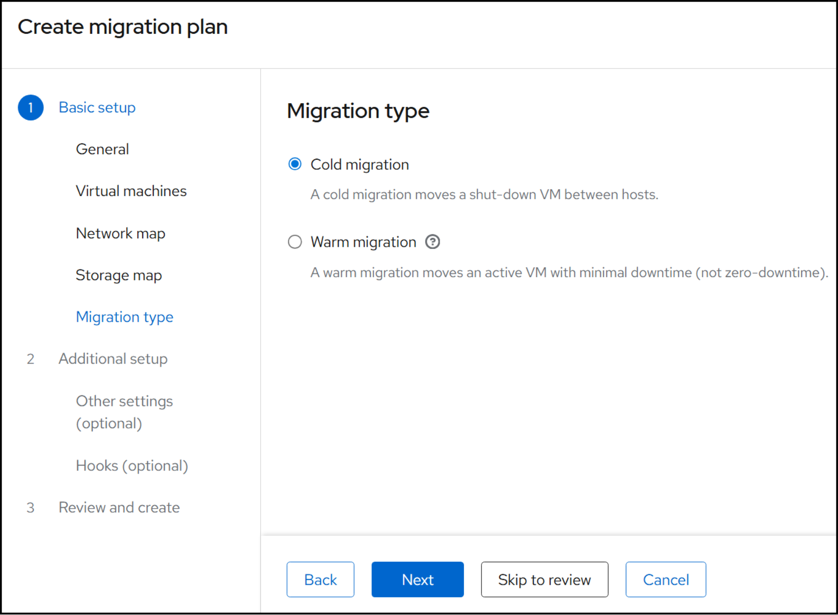
Figure 72. Step 6 – Migration plan
Step 7
Complete one additional task by unchecking the box for Preserve static IPs because a cold migration does not support this. Click Skip to Review.
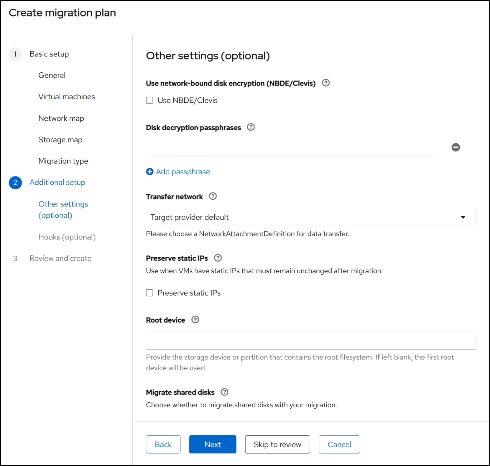
Figure 73. Step 7 – Migration plan
Step 8
Review the summary and click Create plan.
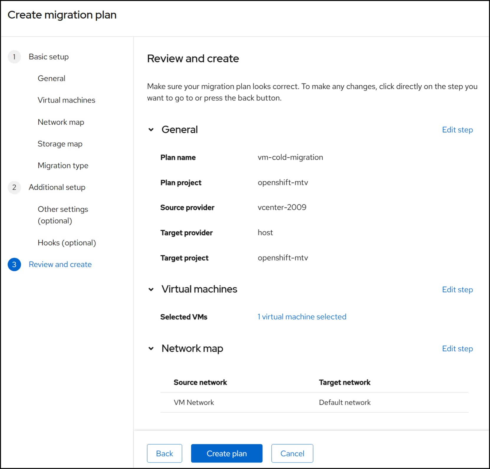
Figure 74. Step 8 – Migration plan
When the migration plan is ready, you will see a Start box. Click to begin the migration.
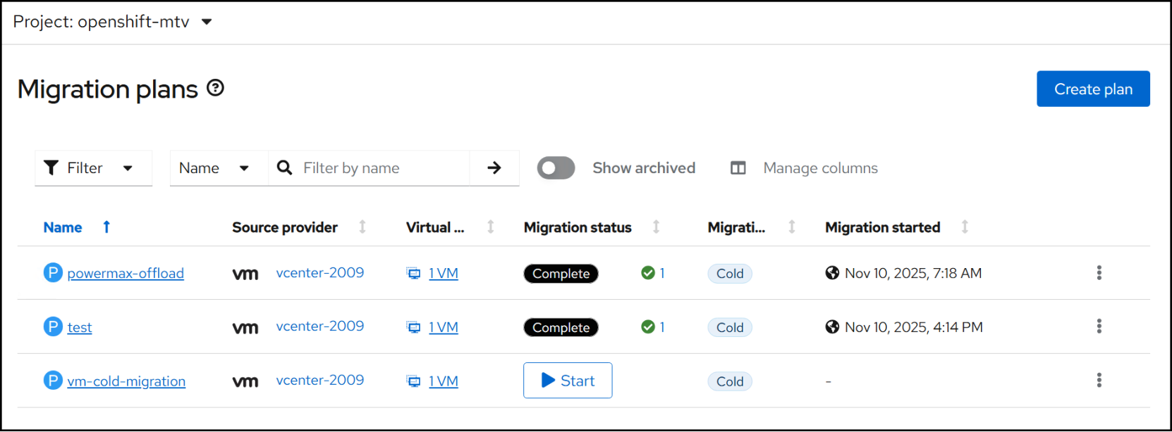
Figure 75. Available migration plan
Once the migration begins, you can follow the progress and various steps by clicking on the 1 VM hyperlink next to the Start button in Figure 75 and then expanding the arrow as in Figure 76.
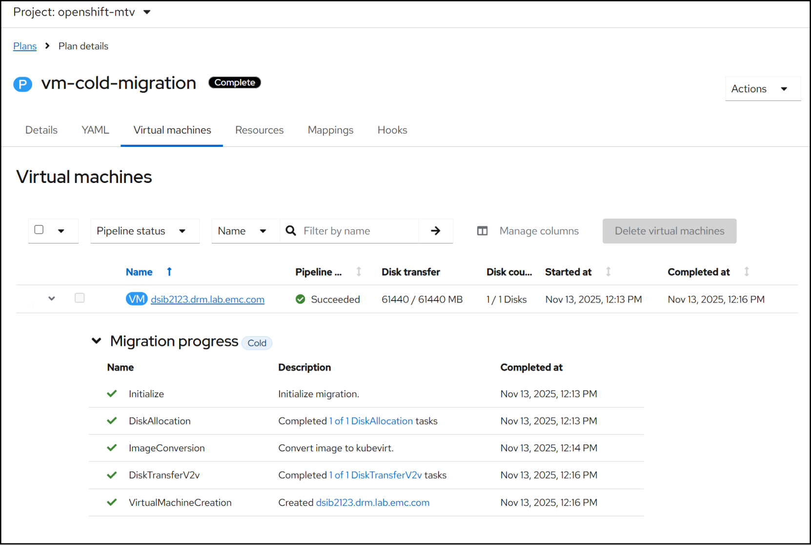
Figure 76. Completed migration
The time to complete a migration is dependent upon the data in the vmdks and the speed of the network. The size of the vmdks is not as relevant since if the disks are empty, they copy quickly. For example, this virtual machine’s 60 GB vmdk only contained 20 GB of written data and therefore copied quickly.
PowerMax data reduction
If you enable data reduction on the PowerMax array’s storage groups and run a VM migration with both the source and target volumes on the same array, you can expect full deduplication. If you use VMware as the source, remember that you only migrate the vmdks, not the datastore. Therefore, the source datastore volume will always have a little more storage allocation than the sum of the vmdks because of VMware VMFS metadata.
Offload option
The Migration Toolkit for Virtualization includes an offload option that significantly decreases VM migration time in comparison to using the VDDK.
Prerequisites
PowerMax offload requires the following prerequisites. Note that these are valid as of the publication of the paper and may change in the future. Always refer to the Red Hat documentation for the most up-to-date information.
- MTV 2.11.0 or higher
- VMware vSphere as the source of the virtual machine
- The vmkfstools-wrapper VIB (installed automatically by default)
- XCOPY must be disabled on the ESXi host unless you patch the HYPERMAX OS/PowerMaxOS. See the XCOPY section below.
Offload process
MTV conducts virtual machines migrations across the IP network, from a source hypervisor to OCP. Depending on the speed of the network and the amount of data to transfer, this can be a time-consuming task. Red Hat determined that, on VMware vSphere, if they could move the copy to the ESXi host, it would reduce the time to complete a migration significantly. They accomplish this with the ESXi utility vmkfstools.
Excluding VM creation tasks, as an example, the offload workflow for a cold migration consists of:
- Create the target device using the storage class specified in the migration plan.
- Mask the target device to the ESXi host where the VM resides using the port group specified in the secret. MTV generates unique auto provisioning objects on PowerMax for the initiator and storage groups, and the masking view.
- Run a vmkfstools clone – this can be a vmdk to RDM or RDM to RDM.
- Unmask the target device from the ESXi host.
- Mask the device to OCP.
OpenShift only powers down the source VM if necessary before a cold migration. It does not delete the VMware source VM after the migration completes.
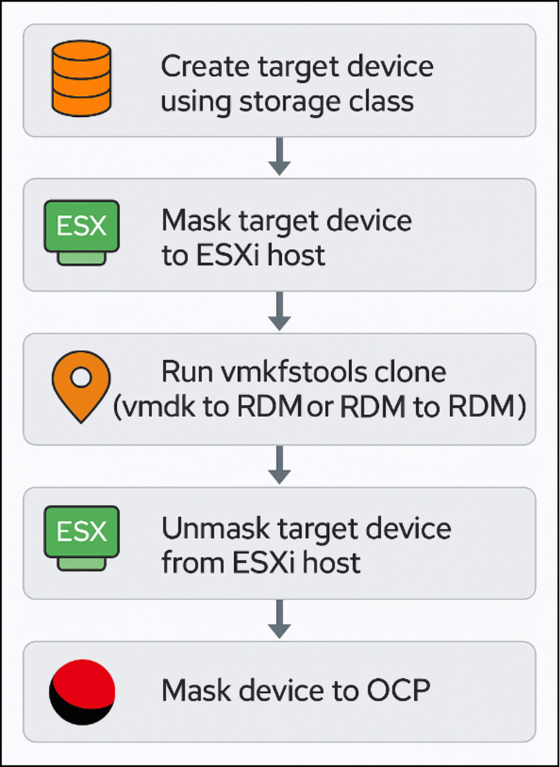
Figure 77. Offload workflow
Note: Warm migrations will use network copy for any changes that occur to the source VM during and after the offload process. This utilizes change block tracking (CBT) on VMware. OpenShift copies on an hourly interval. To avoid excess network copy with offload, Dell recommends cutting over soon after the offload completes.
The offload feature is an option of the storage mapping portion of the migration plan. There are three values you set by drop-down:
- Offload plugin – There is only one option, vSphere XCOPY. Note that this is simply the name of the plug-in and does not mean it requires XCOPY to work.
- Storage secret – A secret which has both generic and specific values for the storage product.
- Storage product – The storage array to use in offload.
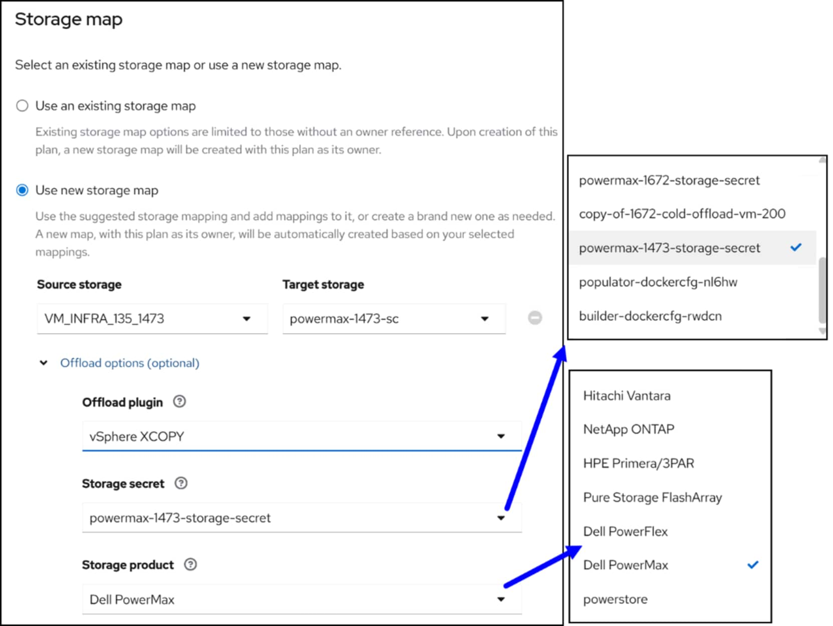
Figure 78. Offload options
vmkfstools-wrapper
The offload uses a custom VIB (vSphere Installation Bundle) installed on ESXi hosts to expose vmkfstools operations via the vSphere API. The first migration plan you run on an ESXi host will place the vmkfstools-wrapper.vib file in the first VM’s VMFS datastore’s top directory. It will install the VIB and it will remain installed for future migrations. There is no manual intervention unless you wish to uninstall it after testing. Once installed, the VIB appears as below.
[root@dsib1040:~] esxcli software vib list |grep RED
vmkfstools-wrapper 0.1.1 REDHAT CommunitySupported
If you prefer a different, manual solution around the use of the VIB, please see the README in the Red Hat documentation section and search for SSH.
XCOPY
The plugin name can be misleading because the offload process does not use XCOPY; it shifts from a network-based copy to using vmkfstools on the ESXi host. If the storage array supports the XCOPY primitive, vmkfstools calls XCOPY during migration because VMware designed it that way. This happens whether MTV runs vmkfstools or the user runs it manually—it’s a vSphere feature. Some arrays, such as Dell PowerFlex, do not support XCOPY, yet the offload still works correctly on those platforms.
While PowerMax supports XCOPY, vmkfstools cannot use it in any release of HYPERMAX OS or PowerMaxOS through version 10.3.0 without an ePack. The following are the necessary ePacks:
- PowerMaxOS 10.3.1.0 - ePack is the Q126 (11248)
- HYPERMAX OS 5978.720.720 - ePack is the Q126 (11249)
If you apply one of these ePacks, you can leave XCOPY enabled (default). If you do not apply the ePack or you are at a version without one, you must disable XCOPY on the ESXi host before you migrate. If you do not, and you issue a vmkfstools clone either manually or as part of a migration offload when XCOPY is enabled, the command will fail with a timeout. For an offload migration, the error will be in the populate-xx log:
I1110 14:01:46.113237 1 vsphere-xcopy-volume-populator.go:219] channel quit clone task failed with exit code 255, stderr: Failed to clone disk: Connection timed out (7208969).
F1110 14:01:46.113274 1 vsphere-xcopy-volume-populator.go:221] clone task failed with exit code 255, stderr: Failed to clone disk: Connection timed out (7208969).
Therefore, it is essential to disable XCOPY on the ESXi host prior to running an offload migration if you do not have the ePack. You can disable it in the UI or CLI. The UI location is in Advanced System Settings of the ESXi host. Set the value to ‘0’ to disable.
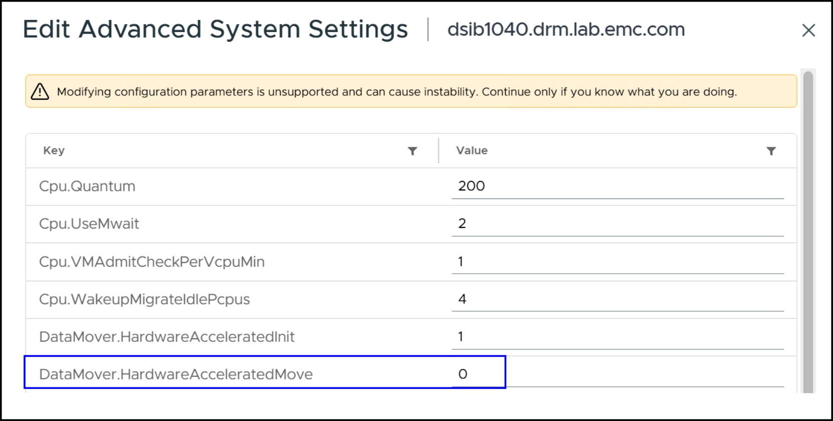
Figure 79. Disabling XCOPY in the UI
For the CLI, login to the ESXi host and issue:
esxcfg-advcfg -s 0 /DataMover/HardwareAcceleratedMove
After you finish migration testing you can re-enable XCOPY.
Storage secret
One of the offload options is the selection of a storage secret. This secret for PowerMax must have the fields in Table 4.
Table 4. PowerMax storage secret for offload
|
Key |
Description |
|
STORAGE_HOSTNAME |
URL of Unisphere for PowerMax, including port |
|
STORAGE_USERNAME |
Username of Unisphere for PowerMax |
|
STORAGE_PASSWORD |
Password of Unisphere for PowerMax |
|
STORAGE_SKIP_SSL_VERIFICATION |
Certificate verification (default is FALSE) |
|
POWERMAX_SYMMETRIX_ID |
PowerMax array ID as used by the CSI driver |
|
POWERMAX_PORT_GROUP_NAME |
PowerMax FC port group name that contains the zoned ports of the ESXi migration host |
All these fields are mandatory except STORAGE_SKIP_SSL_VERIFICATION, but it defaults to false. You can take the values from your PowerMax CSI driver setup. One of the secrets in this setup is below:
apiVersion: v1
kind: Secret
metadata:
name: powermax-1473-storage-secret
namespace: openshift-mtv
type: Opaque
stringData:
STORAGE_HOSTNAME: "https://172.16.105.200:8443"
STORAGE_USERNAME: "smc"
STORAGE_PASSWORD: "smc"
POWERMAX_SYMMETRIX_ID: "000120001473"
POWERMAX_PORT_GROUP_NAME: "mtv_group_pg"
Create this secret prior to configuring a migration plan.
Network and offload performance
VM migration over the network can take significantly longer than using the offload feature. Network speed is a critical factor for network-based migration, but it does not affect offload performance.
The following results compare two migration methods—network-based and offload—for the same VM. This VM contains a single, fully populated 100 GB VMDK. The first image shows the network migration, and the second shows the offload migration.
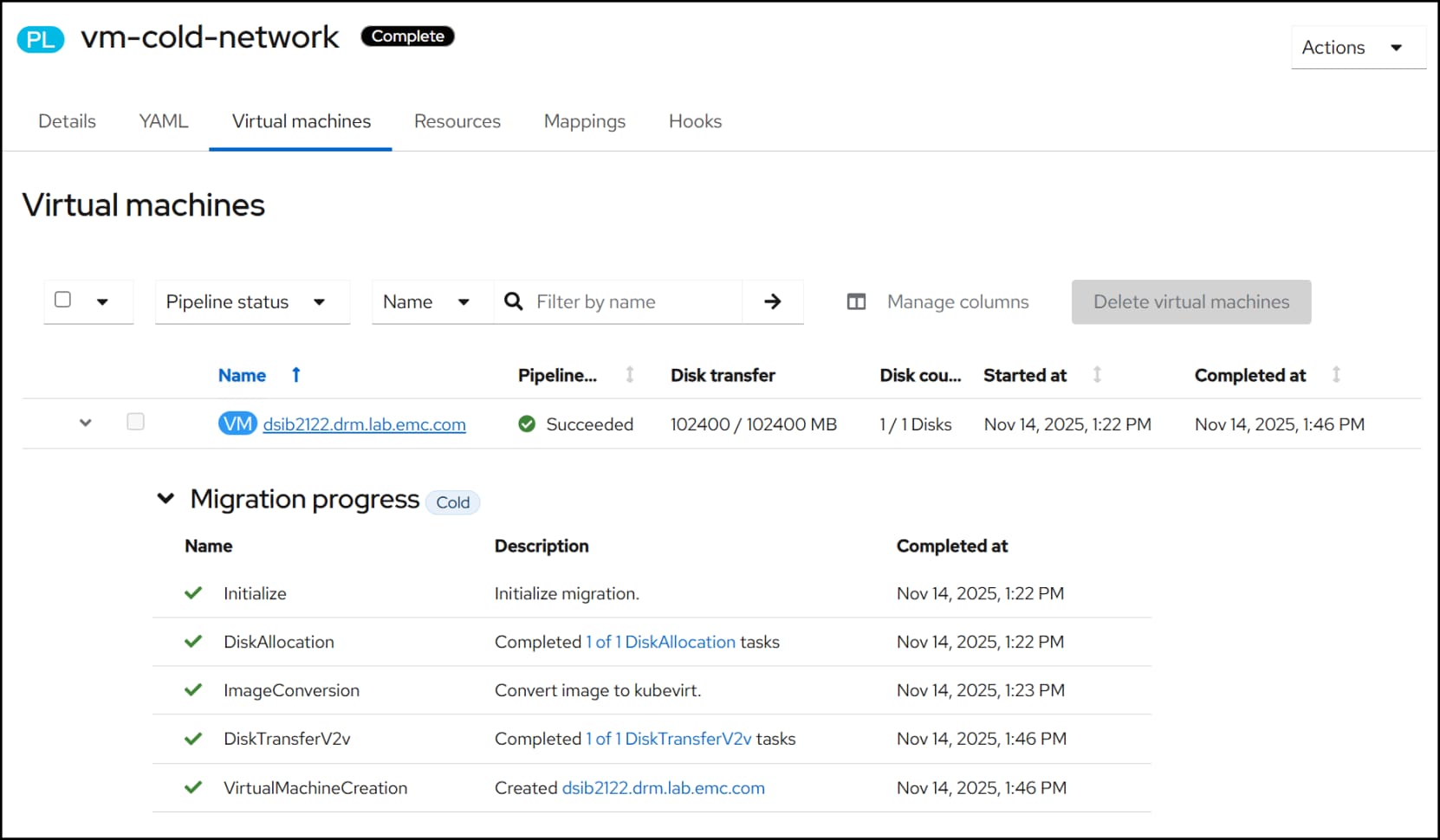
Figure 80. Network migration of dsib2122.drm.lab.emc.com
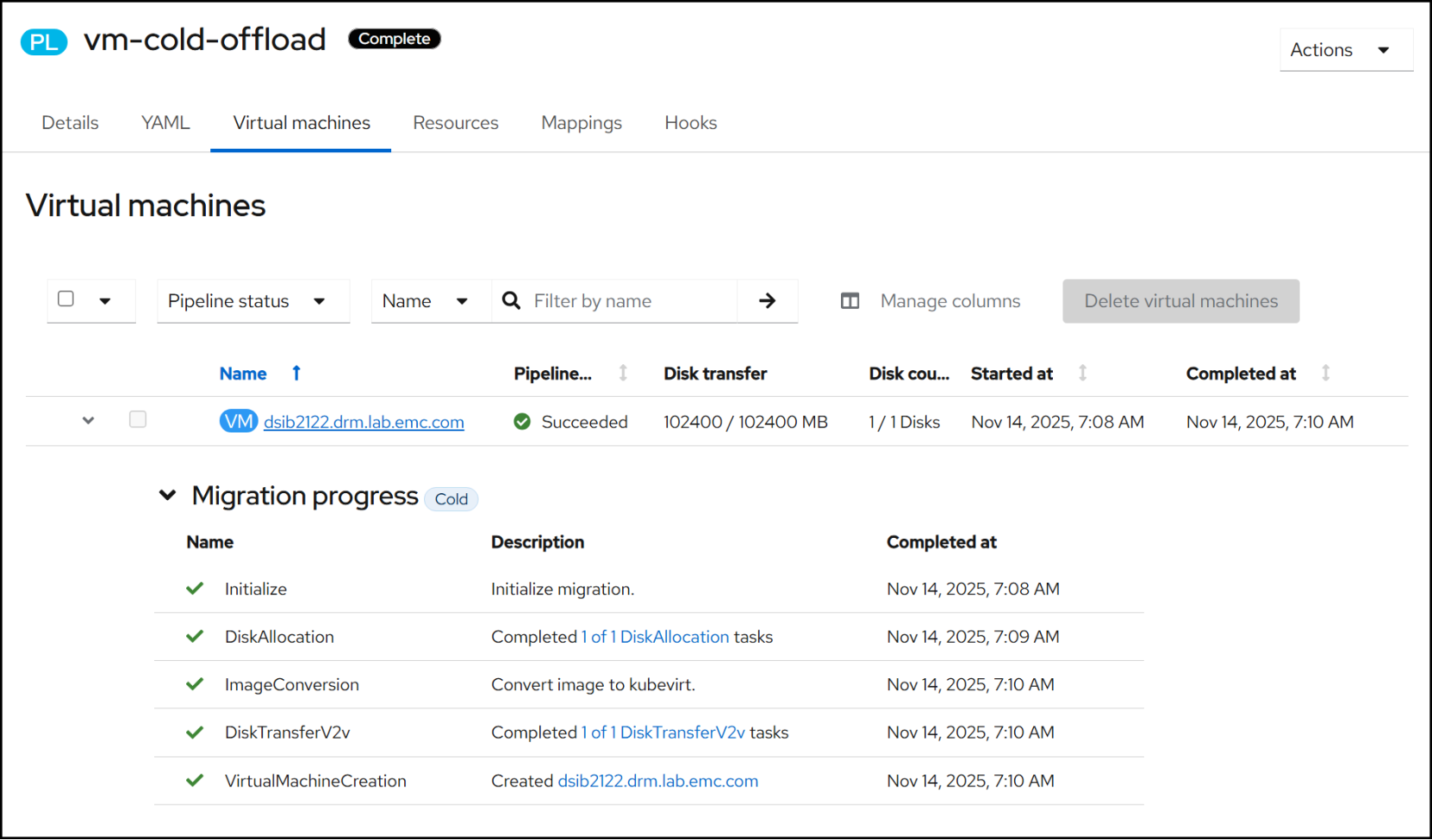
Figure 81. Offload migration of dsib2122.drm.lab.emc.com
Note: Unlike a network copy, the offload feature does not show Disk transfer progress in the UI. The amount copied will remain at zero until completion, at which time it will update to the disk size.
The network migration took 24 minutes to transfer 100 GB, while the offload completed in just 2 minutes—a 10× improvement. Faster IP infrastructure can reduce network migration time, but it will always be significantly slower than offload.
Different PowerMax source and target
Offload will work between two different PowerMax arrays by meeting the following conditions:
- Target and source arrays configured in the CSI driver.
- Migration ESXi host has access to both arrays through host groups.
- A secret exists for the target array with the correct port group name.
- There is an available storage class for the target array.
Raw Device Mappings (RDM)
RDMs with MTV and offload is an interesting use case because MTV does not support RDMs when using network copy. You can see below the “Critical concerns” you get for the VM, clearly pointing out the restriction.
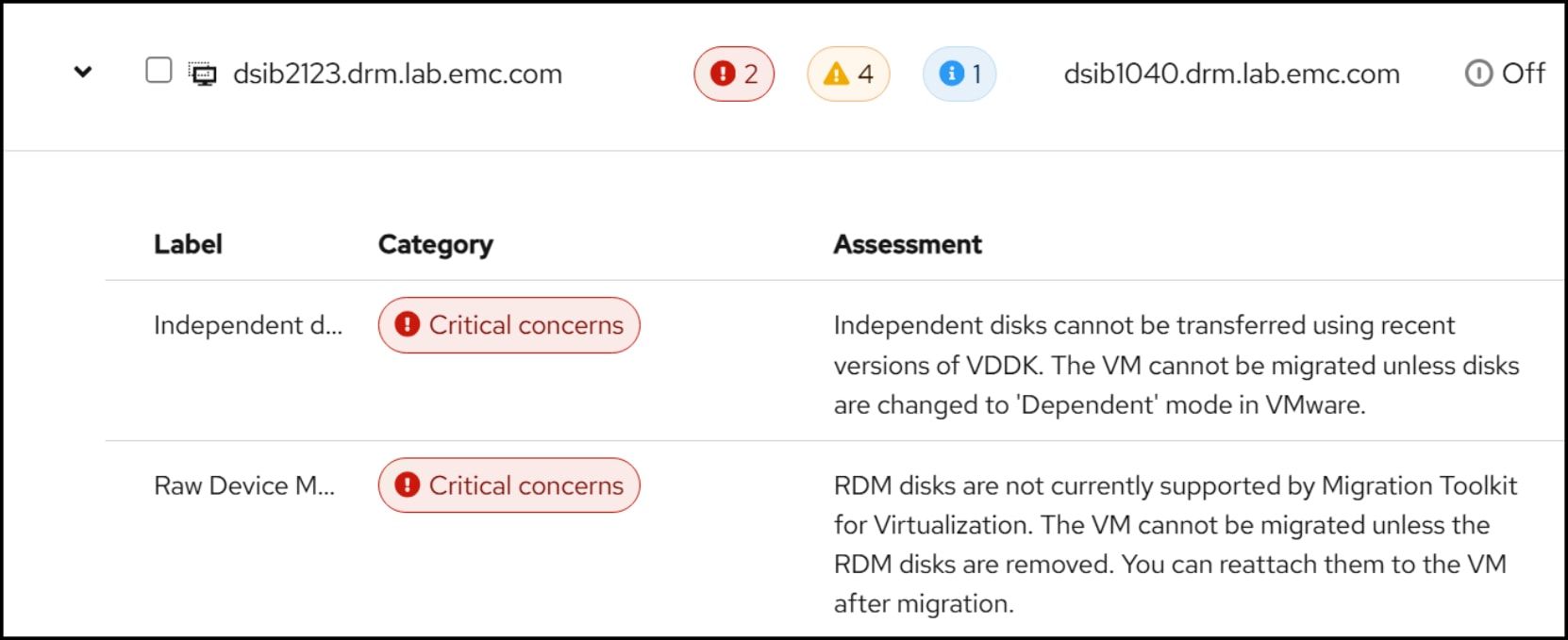
Figure 82. RDM critical concern
When you use offload, however, you are not doing a network copy but a vmkfstools clone. A vmkfstools clone supports RDMs, therefore offloading works with RDMs. When you configure the VM in the migration plan, however, you must acknowledge the restriction:
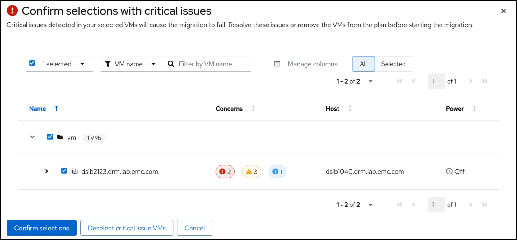
Figure 83. Confirm selections despite RDM
After confirming, the migration plan proceeds as any non-RDM plan.
Note: The offload supports VMware virtual volumes (vVols).
Conclusion
Summary
References
Dell Technologies documentation
Red Hat documentation
Appendix
Troubleshooting
The following sections provide troubleshooting information for common problems encountered in OpenShift Container Platform (OCP). Review these steps before contacting support.
Installation disks
After Step 4 Host discovery, the Assisted Installer will display the storage options. If you are using a basic Dell server configuration, there are typically two disks which may or may not use RAID. If you see a considerable number of disks listed, however, it is likely the host sees mapped volumes from external storage. In addition, you may see a warning about multipath. In Figure 84, both of these are the case. There are seventeen devices for each host and two of the hosts use multipath.
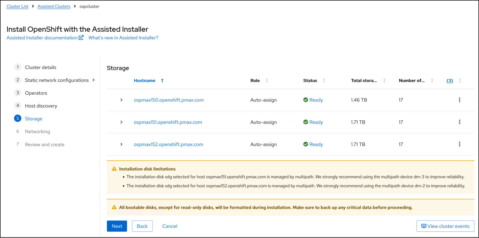
Figure 84. Too many disks
In such circumstances, start by expanding one of the hosts using the greater than symbol (>). The installer lists these disks in Figure 85. Note that this initial subset is comprised of only PowerMax devices. The installer chose one of these PowerMax devices (sdg) for installation. Note the gray checkbox indicating you cannot change it. As this host is not booting to PowerMax, you would need to unmask these devices from the host so that only the local devices remain. This will ensure OCP installs in the correct location.
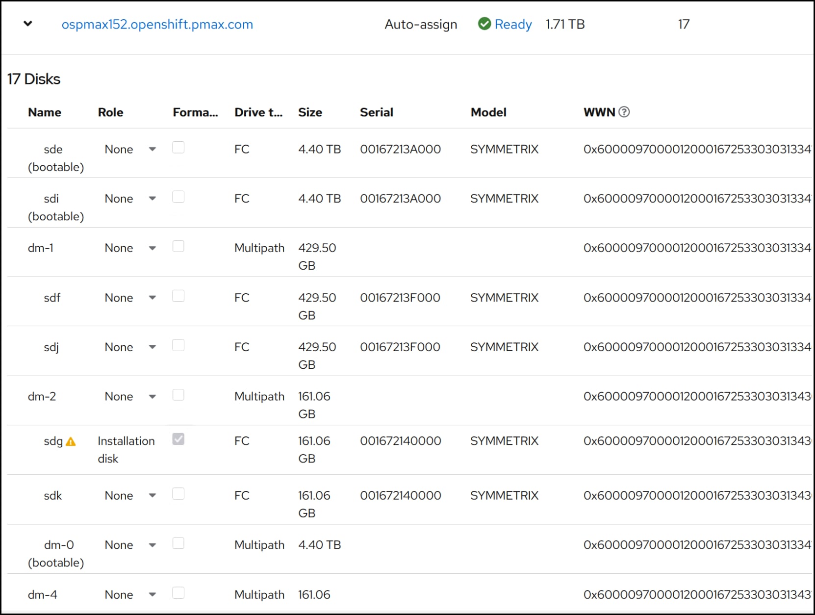
Figure 85. Host disks
After you unmask the device, you must restart the Assisted Installer. Red Hat cannot dynamically update the disks. When the installer returns to the storage step, the new list in Figure 86 only includes a single, small PowerMax placeholder device. The installer now correctly sets the local installation disk.
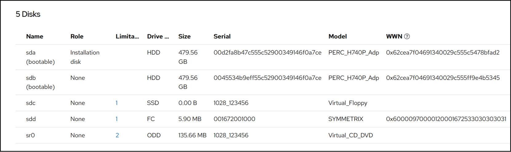
Figure 86. Post-unmasking
Boot from SAN
Conversely, if you install on a server that does not have an internal disk that is at least 100 GB, you will see an insufficient disk size error for the installation. In the section Scaling, we covered adding a host to an OCP cluster which is in this state. The internal boot disk is 16 GB and while that is sufficient for many operating systems, it is not for Red Hat’s CoreOS. Therefore, we configured the host to boot to the PowerMax instead, presenting a 200 GB device. The installer, in our example, recognizes eight paths to the device and recommends using the multipath device which you can see in Figure 87 as dm-0.
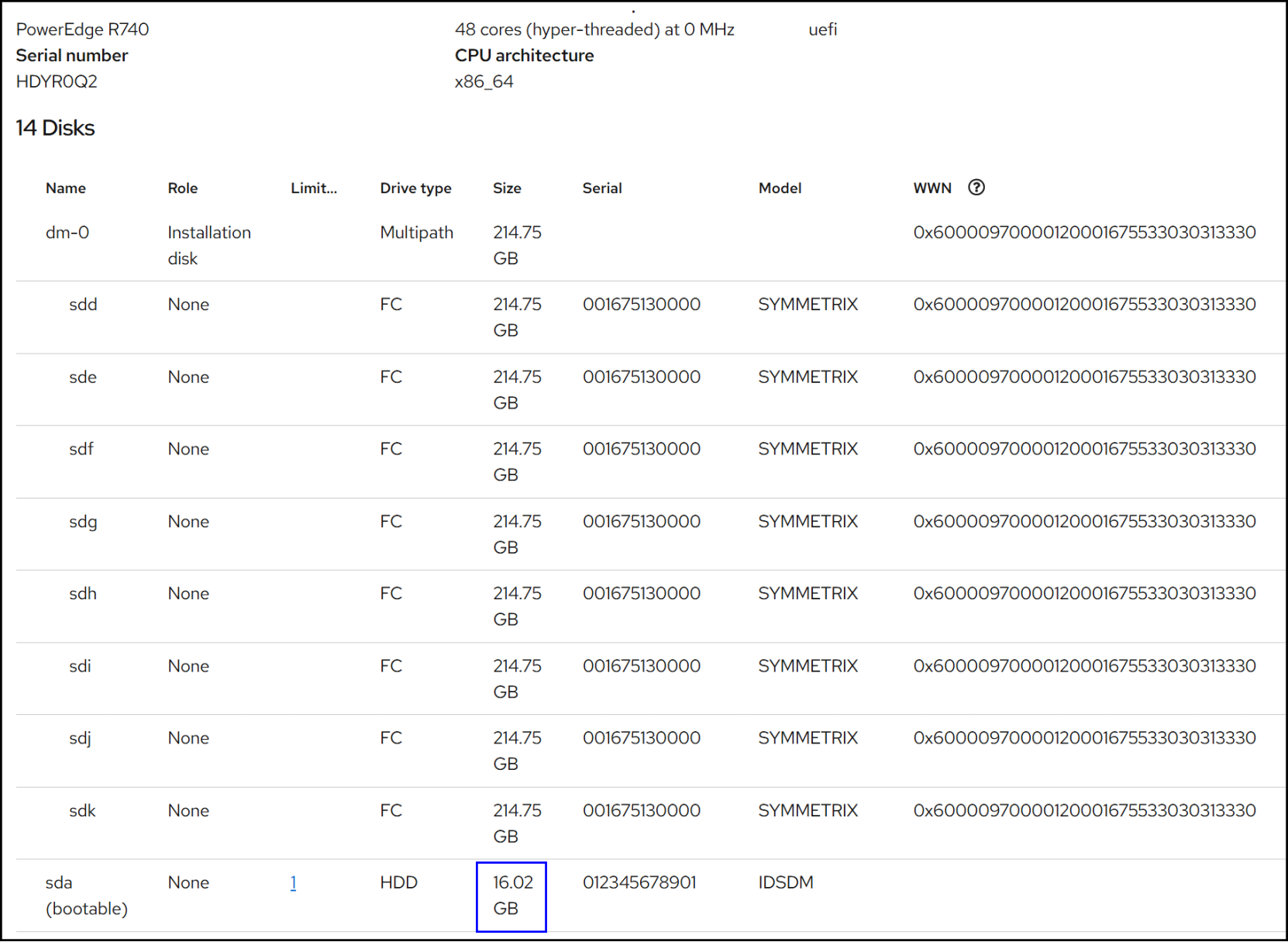
Figure 87. Boot disk insufficient for installation
If you use Boot from SAN, be sure to follow the Dell documentation for configuring the server. It is beyond the scope of this paper. Booting from PowerMax does offer an advantage over a local disk install because you have access to the replication technologies of TimeFinder and SRDF for local and remote replication if so desired.
DNS entries
In Step 6 Networking of the installation you supply two IP addresses, one for Ingress and one for the API. OpenShift generates a number of hosts or aliases that must resolve to these IP addresses. For example, in this environment we used IP 172.16.105.160 and 161. Upon completion, OpenShift lists the following:
172.16.105.160
api.ospcluster.openshift.pmax.com
172.16.105.161
oauth-openshift.apps.ospcluster.openshift.pmax.com
172.16.105.161
console-openshift-console.apps.ospcluster.openshift.pmax.com
172.16.105.161
grafana-openshift-monitoring.apps.ospcluster.openshift.pmax.com
172.16.105.161
thanos-querier-openshift-monitoring.apps.ospcluster.openshift.pmax.com
172.16.105.161
prometheus-k8s-openshift-monitoring.apps.ospcluster.openshift.pmax.com
172.16.105.161
alertmanager-main-openshift-monitoring.apps.ospcluster.openshift.pmax.com
There are two options for resolution: DNS or hosts file on your bastion server. Unless you always use the same host to access the OCP cluster, DNS is a better option to choose. We added our entries in PowerShell, though you can use a command prompt or the DNS Manager.
PowerShell
Import-Module DnsServer # if needed
Add-DnsServerResourceRecordA -Name "api.ospcluster" -ZoneName "openshift.pmax.com" -IPv4Address "172.16.105.160" -ComputerName "localhost"
Add-DnsServerResourceRecordA -Name "*.apps.ospcluster" -ZoneName "openshift.pmax.com" -IPv4Address "172.16.105.161" -ComputerName "localhost"
Test an address for resolution.
PS C:\Users\Administrator> nslookup prometheus-k8s-openshift-monitoring.apps.ospcluster.openshift.pmax.com
Server: UnKnown
Address: 172.16.105.44
Name: prometheus-k8s-openshift-monitoring.apps.ospcluster.openshift.pmax.com
Address: 172.16.105.161
PS C:\Users\Administrator>
Adding a VM bridged network
If you wish to configure a free NIC on your OCP nodes for use as VM network, you can use a MachineConfig file similar to the following for that purpose. Note that there are placeholder UUIDs in both source data. Be sure to update appropriately.
apiVersion: machineconfiguration.openshift.io/v1
kind: MachineConfig
metadata:
# The label specifies which machine config pool (MCP) this config applies to.
# Change 'worker' to 'master' if you need it on control plane nodes.
labels:
machineconfiguration.openshift.io/role: worker
name: 20-worker-bridge-eno3
spec:
# The configuration uses Ignition files to place NetworkManager connection profiles.
# Ignition base64-encodes the content of the target file.
config:
ignition:
version: 3.2.0
# The 'files' array contains the two NetworkManager configuration files.
files:
# --------------------------------------------------------
# Bridge Master Connection (br-eno3)
# --------------------------------------------------------
- path: /etc/NetworkManager/system-connections/br-eno3.nmconnection
mode: 0600
overwrite: true
contents:
source: data:text/plain;charset=utf-8;base64,W2Nvbm5lY3Rpb25dCmlkPWJyLWVubzMKdXVpZD1kNjFhN2I4ZS0xNzNmLTQyN2YtOTRhMC01NjI3NTFmOTJjMzAKdHlwZT1icmlkZ2UKaW50ZXJmYWNlLW5hbWU9YnItZW5vMwphdXRvY29ubmVjdD10cnVlCgpbYnJpZGdlXQoKW2lwdjRdCm1ldGhvZD1kaXNhYmxlZAoKW2lwdjZdCm1ldGhvZD1pZ25vcmUK
# --------------------------------------------------------
# Ethernet Slave Connection (eno3)
# --------------------------------------------------------
- path: /etc/NetworkManager/system-connections/bridge-slave-eno3.nmconnection
mode: 0600
overwrite: true
contents:
source: data:text/plain;charset=utf-8;base64,W2Nvbm5lY3Rpb25dCmlkPWJyaWRnZS1zbGF2ZS1lbm8zCnV1aWQ9YTNjNGY3YzgtNGQ1ZS00YjZmLTkwYTEtMmIzYzRkNWU2ZjdhCnR5cGU9ZXRoZXJuZXQKaW50ZXJmYWNlLW5hbWU9ZW5vMwptYXN0ZXI9YnItZW5vMwpzbGF2ZS10eXBlPWJyaWRnZQphdXRvY29ubmVjdD10cnVlCgpbZXRocnQdCgpbZGVmYXVsdF0KCm1ldGhvZD1kaXNhYmxlZAoKW2lwdjZdCm1ldGhvZD1pZ25vcmUK
SSH node access
If you forget to supply a public key during the installation process (Figure 15), you will be unable to SSH into your nodes. Under normal operating conditions, this is desirable; however, there are situations where it is necessary. For example, we detail in this paper how to use a free NIC for a VM network by enabling a bridge. We create the bridge through OS commands which require SSH access. It is possible, however, to create a MachineConfig file to authorize your bastion host to connect even after installation.
Step 1
Locate your public and private SSH key on the bastion host in the ~/.ssh directory. If the files do not exist, create them using ssh-keygen. Copy the contents of the public file.
pshift105:~/.ssh # more id_ed25519.pub
ssh-ed25519 AAAAC3NzaC1lZDI1NTE5AAAAIAA0cejdmNJw9sBajBAzCxHeYqgNVOEZKSb4jREpMZcW openshift@baremetal
Step 2
Create two MachineConfig files, one for workers and one for master. If you have a simple three node cluster you do not require the worker file; however, if you add worker nodes in the future, creating both configurations will ensure new nodes get the key.
Worker file
Supply your public key under sshAuthorizedKeys.
apiVersion: machineconfiguration.openshift.io/v1
kind: MachineConfig
metadata:
name: 99-core-ssh-worker
labels:
machineconfiguration.openshift.io/role: worker
spec:
config:
ignition:
version: 3.2.0
passwd:
users:
- name: core
sshAuthorizedKeys:
- ssh-ed25519 AAAAC3NzaC1lZDI1NTE5AAAAIAA0cejdmNJw9sBajBAzCxHeYqgNVOEZKSb4jREpMZcW openshift@baremetal
Master file
apiVersion: machineconfiguration.openshift.io/v1
kind: MachineConfig
metadata:
name: 99-core-ssh-master
labels:
machineconfiguration.openshift.io/role: master
spec:
config:
ignition:
version: 3.2.0
passwd:
users:
- name: core
sshAuthorizedKeys:
- ssh-ed25519 AAAAC3NzaC1lZDI1NTE5AAAAIAA0cejdmNJw9sBajBAzCxHeYqgNVOEZKSb4jREpMZcW openshift@baremetal
Save both as YAMLs.
Step 3
Apply each file:
oc apply -f 99-core-ssh-worker.yaml
oc apply -f 99-core-ssh-master.yaml
You can view the rollout by watching:
cc get mcp -w
The output will be similar to below. Once the UPDATED column is True, the job is complete.
pshift105:~/.ssh # oc get mcp -w
We edited the output below for readability. You can see the READYMACHINECOUNT move for the master move from 0 to 3 as each updates.
NAME CONFIG UPDATED UPDATING DEGRADED MACHINECOUNT READYMACHINECOUNT UPDATEDMACHINECOUNT
master rendered-master-xxx False True False 3 0 0
worker rendered-worker-xxx True False False 1 1 1
master rendered-master-xxx False True False 3 1 1
master rendered-master-xxx False True False 3 1 1
master rendered-master-xxx False True False 3 2 2
master rendered-master-xxx False True False 3 2 2
master rendered-master-xxx True False False 3 3 3
When the update completes, you can login to your OCP node. Note that Red Hat does produce a warning message about not using direct SSH access.
pshift105:~/.ssh # ssh core@pshift101.powermax.os.com
Red Hat Enterprise Linux CoreOS 418.94.202505062142-0
Part of OpenShift 4.18, RHCOS is a Kubernetes-native operating system
managed by the Machine Config Operator (`clusteroperator/machine-config`).
WARNING: Direct SSH access to machines is not recommended; instead,
make configuration changes via `machineconfig` objects:
https://docs.openshift.com/container-platform/4.18/architecture/architecture-rhcos.html
---
Last failed login: Fri Nov 7 15:19:42 UTC 2025 on tty1
There were 4 failed login attempts since the last successful login.
[systemd]
Failed Units: 1
NetworkManager-wait-online.service
[core@pshift101 ~]$