PowerFlex CSM Resiliency and Replication on OpenShift Virtualization

Oct 19, 2026
PowerFlex CSM Resiliency and Replication on OpenShift Virtualization This whitepaper describes and validates the high availability and disaster recovery of VMs running on Red Hat OpenShift Virtualization with Dell PowerFlex software-defined infrastructure using the Dell CSM resiliency and replication module.

Executive Summary

Executive Summary

In today's digital-first era, businesses are driven by massive amounts of data. As data volumes scale and environments modernize toward cloud-native architectures, safeguarding mission-critical workloads while maintaining steady operations becomes vital. To meet defined recovery time objective (RTO) and recovery point objective (RPO) targets, organizations need a robust high availability and disaster recovery strategy that enables trustworthy, rapid recovery while preventing or minimizing data loss.

This white paper presents the unified high availability and disaster recovery solution for safeguarding VMs running on the Red Hat OpenShift Virtualization platform with Dell PowerFlex software-defined infrastructure. The solution provides storage-native, policy-driven replication and resiliency by using the PowerFlex Container Storage Interface (CSI) driver along with the Dell Container Storage Modules (CSM) Replication and Resiliency, enabling enterprise class high availability (HA) and disaster recovery (DR) capabilities.

Dell PowerFlex delivers high-throughput, linearly scalable, fault-tolerant primary storage through protection domains and fault sets. Red Hat OpenShift uses Policy-as-Code (PaC) to enforce protection through native Kubernetes construct to provide consistent security and auditable operations across hybrid cloud environments. Together, these technologies deliver a unified, cloud-native protection fabric that supports both local resilience and multisite recovery to safeguard critical data, streamline runbooks with GitOps-ready workflows, and sustain business continuity.

Revisions

Table 1. Revision history
Date Part Number Description
May 2026 H04699 Initial release

Audience

This white paper is intended for technical professionals and decision makers responsible for the design, deployment, and operation of enterprise virtualization and high availability (HA) and disaster recovery (DR) solutions. The primary audience includes database administrators, system engineers, field consultants, IT administrators, technical architects, and infrastructure leaders involved in implementing HA and DR for VMs running on OpenShift Virtualization using Dell PowerFlex CSM Replication and Resiliency modules.

Readers are expected to possess foundational knowledge of PowerFlex, Red Hat OpenShift Container Platform (OCP), OpenShift Virtualization, and modern container technologies. Familiarity with core infrastructure domains such as storage, compute, and networking architectures is assumed.

In addition, readers should have a working understanding of enterprise data protection concepts such as storage replication, fault tolerance, high availability, backup and recovery, and disaster recovery. This context is essential to fully evaluate the architectural considerations, design decisions, and operational implications discussed throughout this white paper.

Terminology

The following table provides definitions for some of the terms that are used in this document.

Table 2. Terminology
Term Definition
CSI Container Storage Interface
DB Database
Dell CSM Dell Container Storage Module
DR Disaster Recovery
HA High availability
LCM Life Cycle Management
OCP OpenShift Container Platform
PVC Persistent Volume Claim
RCG Replication Consistency Group
RG Replication Group
RPO Recovery Point Objective
SDC Storage Data Client, a Dell PowerFlex component installed on a compute node that provides access to PowerFlex block volumes.
SDR Storage Data Replicator, a Dell PowerFlex component installed on storage nodes to manage storage replication.
SDS Storage Data Server, a Dell PowerFlex component that controls local disks and aggregates them into a storage pool.
VLAN Virtual Local Area Network
VM Virtual Machine

We value your feedback

Dell Technologies and the authors of this document welcome your feedback on the solution and the solution documentation. Contact the Dell Technologies Solutions team by email.

Author
Vinutha Shenoy

Product overview

PowerFlex family

PowerFlex software-defined storage enables broad consolidation across the data center, encompassing most block storage workloads with ease. The software-first architecture enables automation and programmability of the complete infrastructure stack. PowerFlex provides scalability, performance, and resiliency to enable effortless adherence to stringent workload SLAs.

The PowerFlex family provides a foundation that combines compute and high-performance storage resources in a managed, unified fabric. PowerFlex comes in flexible consumption options (rack, appliance, and custom nodes) that enable various independent, disaggregated architectures. PowerFlex is ideal for high-performance applications and databases, building an agile private/hybrid cloud, or consolidating resources across heterogeneous environments.
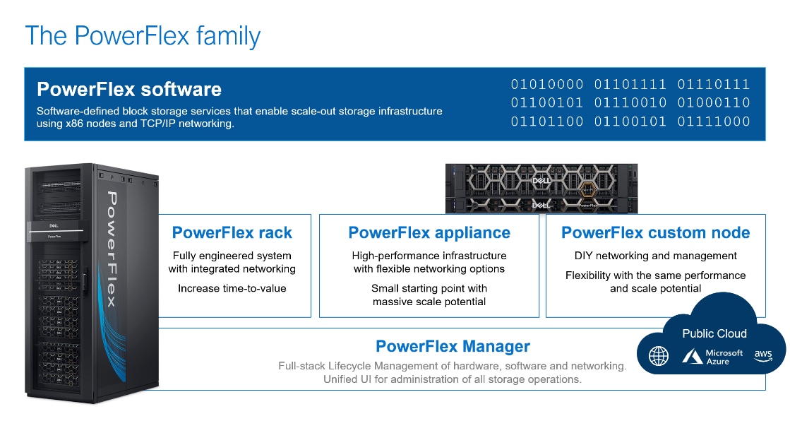
Figure 1. PowerFlex family
Image detailing the PowerFlex family of products including rack, appliance, and custom nodes.

PowerFlex software components

Software is the key differentiation in the PowerFlex offer. PowerFlex software components not only provide the distributed software-defined storage services but also help simplify infrastructure management and orchestration.

PowerFlex core software

PowerFlex is a software-defined scale-out block storage service that is designed to deliver flexibility, elasticity, and simplicity with predictable high performance and resiliency at scale.

For more details about PowerFlex 4.x, see PowerFlex 4.x specifications.

For more details about PowerFlex 5.x, see PowerFlex 5.x specifications.

PowerFlex Manager

PowerFlex Manager enables comprehensive IT Operational Management (ITOM) and Life Cycle Management (LCM) capabilities that span compute as well as storage infrastructure, from BIOS and firmware to nodes, software, and networking.

PowerFlex deployment architectures

PowerFlex software-defined storage can be deployed in a disaggregated architecture (independently scalable compute and storage layers).

Independent architecture

In an independent, or disaggregated, architecture some nodes provide storage capacity for data in applications, while other separate and independent nodes provide compute resources for applications and workloads. Compute and storage resources can be scaled independently by adding nodes to the cluster while it remains active. This separation of compute and storage resources helps to minimize software licensing costs in certain situations. This architecture is ideal for high-performance databases and application workloads.

Disaggregation gives organizations the freedom to choose different LCM options that best align with their operational models. Not only can PowerFlex Manager manage the LCM of PowerFlex storage infrastructure, it can also manage LCM of PowerFlex compute nodes. With this freedom, there is also the choice to manage compute estates that connect to PowerFlex with other tooling.

PowerFlex consumption options

PowerFlex rack

PowerFlex rack is a software-defined infrastructure platform that combines compute and high-performance storage resources in a managed unified network. This rack-based engineered system, with integrated networking, enables customers to achieve the scalability and management requirements of a modern data center.

PowerFlex appliance

PowerFlex appliance is a PowerEdge-based server which has been configured to be a node in a software-defined storage deployment that runs PowerFlex software components. This offering allows customers the flexibility and savings to bring their own compatible networking or make use of full network automation using a supported set of Dell or Cisco switches.

PowerFlex custom nodes

PowerFlex Custom Nodes are validated PowerEdge-based server building-blocks configured for use with PowerFlex. They are available with thousands of configuration options for customers who prefer to build their own environments.

PowerFlex in the public cloud

PowerFlex software storage services can be deployed on recommended instances (with attached storage) in Amazon Web Services or Microsoft Azure. Only the EC and MG data layout as well as the Independent (disaggregated) architecture are supported. Where available, native asynchronous replication may be used to migrate data between cloud and on-premises PowerFlex systems, or to establish cloud-based BC/DR data protection schemes. This architecture is ideal for high-performance databases and application workloads.

PowerFlex CSI/CSM

An important component outside of PowerFlex that enables a flexible consumption model for Kubernetes is the PowerFlex CSI driver, developed as a part of the Dell Kubernetes strategy. After loading the CSI driver for PowerFlex into Kubernetes, it can be used to provision persistent volumes from the underlying PowerFlex storage resource. If the Kubernetes deployment is running low on PowerFlex storage resources, you can add PowerFlex storage nodes to increase the system capacity and performance.

The CSI driver connects the PowerFlex system and Kubernetes deployments. It is a storage broker which dynamically provisions volumes from PowerFlex through the PowerFlex API gateway to the Kubernetes cluster. Once the volume is available on PowerFlex, it is immediately mapped to the requesting pod. If a pod is destroyed or rescheduled, the CSI plug-in ensures that the volumes are remapped upon rescheduling of that pod. 

Customers running Kubernetes clusters on PowerFlex use the Dell Container Storage Modules (CSM), which extend the CSI driver capabilities. These modules:

  • Provide enterprise storage capabilities to Kubernetes for cloud-native stateful applications.
  • Reduce management complexity, so that developers can independently use enterprise storage with ease and automate daily operations.
  • Extend storage functionality and capabilities beyond using the CSI driver alone.

These modules include replication, observability, authorization, application mobility, and resiliency.

PowerFlex supports multiple operating systems. PowerFlex is validated with the leading Kubernetes distributions as shown in the following figure:
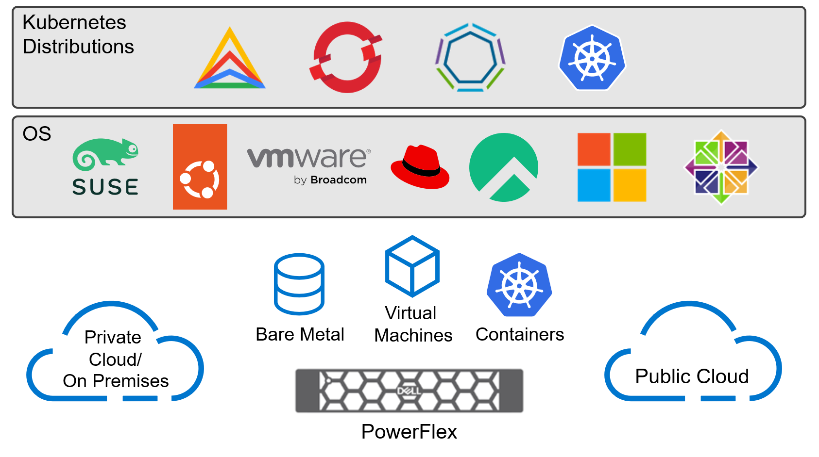
Figure 2. PowerFlex for different Kubernetes distributions
Various operating systems and Kubernetes distributions supported on PowerFlex

PowerFlex CSM Replication module

Dell brings Kubernetes native disaster recovery for OpenShift by combining PowerFlex native asynchronous replication with the CSM Replication module. PowerFlex provides storage level, asynchronous data replication between independent clusters, where each cluster can act as both a source and a target. This bidirectional design enables flexible, geographically distributed architectures while ensuring resilient data protection for stateful workloads. Replication is handled at the array level, minimizing application impact and maintaining storage consistency.

The CSM Replication module extends the PowerFlex CSI driver to make this capability Kubernetes aware and declarative. Using Kubernetes CRDs, it orchestrates volume and volume group replication across clusters, supporting both planned migrations and unplanned disaster recovery without application changes. CSM replication coordinates failover and recovery workflows directly within the Kubernetes control plane and is deployed and managed through the CSM Operator. Together, PowerFlex and CSM Replication provide a simple, transparent, and enterprise-grade DR solution for OpenShift environments.

PowerFlex CSM Resiliency module

The CSM Resiliency module strengthens application availability and fault tolerance for Kubernetes workloads consuming PowerFlex persistent storage. It proactively improves storage behavior during node, pod, and infrastructure failures by enabling automated recovery actions and faster remediation. The module leverages Kubernetes health signals and PowerFlex storage capabilities to improve volume attachment reliability and reduce recovery time objectives. By coordinating failure handling across both the storage and orchestration layers, it minimizes application disruption and enhances platform stability. Dell delivers and manages the Resiliency module through the CSM Operator to ensure consistent behavior across OpenShift clusters.

Red Hat OpenShift

OpenShift Container Platform

Red Hat OpenShift Container Platform provides developers and IT organizations with a hybrid cloud application platform for deploying both new and existing applications on secure, scalable resources with minimal configuration and management overhead. The OpenShift Container Platform provides an enterprise-grade Kubernetes environment for building, deploying, and managing container-based applications, alongside virtualized workloads, across any data center where Red Hat Enterprise Linux is supported.

For more information, see Red Hat OpenShift Container Platform documentation.

OpenShift Assisted Installer

OpenShift Assisted Installer provides a SaaS-based managed service to deploy OpenShift clusters in various configurations, including bare metal servers and on-premises nodes, from the Red Hat Hybrid Cloud Console. You do not require a dedicated bootstrap node before installing a cluster and you do not need to preinstall Red Hat CoreOS on the nodes. Cluster deployment parameters are populated within the web UI and nodes are booted with an ISO image that is downloaded to complete the cluster deployment.

For more information, see OpenShift Assisted Installer blog.

OpenShift Virtualization

OpenShift Virtualization is an add-on to OpenShift Container Platform that allows you to run and manage VM workloads alongside container workloads. OpenShift Virtualization is based on upstream KubeVirt, which implements the deployment and management of VMs using Kubernetes constructs such as PVCs and pods. The following figure shows the KubeVirt components that are implemented in OpenShift Virtualization:
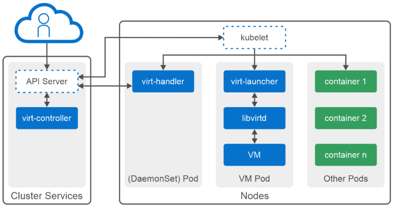
Figure 3. OpenShift Virtualization architecture
Diagram illustrating Kubernetes architecture integrating virtual machines and containers. It shows Cluster Services with API Server and virt-controller, Nodes containing virt-handler, virt-launcher with libvirtd managing VM Pods, and multiple container Pods, using blue and green color coding to differentiate components. AI-generated content may be incorrect.

The KubeVirt components of OpenShift Virtualization are:

virt-controller
An operator that detects when new VM resources are created and creates the corresponding pod in which the VM runs. After the pod is scheduled to a node, the virt-controller provides the VM object with the node name and hands off to the virt-handler.
virt-handler
A daemon set running on every compute node, which performs all the steps that are required to move a VM object to the p state. This task is performed by referencing the VM specification and then creating a libvirtd domain on the VM pod. In the context of VMs, "p-state" refers to a processor's performance state, which dictates its operating frequency and voltage, allowing for dynamic adjustments to power consumption and performance based on workload demands. Virt-handler turns off the corresponding domain after the VM object is deleted.
virt-launcher
As the primary container running on every VM pod, this component creates the necessary groups and namespaces to host a VM after it is provided with a VM object to deploy from virt-handler. An instance of libvirtd hosted within virt-launcher is used to create the VM. After the VM is created, virt-launcher waits until the VM process is completed and then terminates itself. Virt-launcher also attempts to prevent preemptive shutdowns from Kubernetes to ensure that the VM exits before virt-launcher terminates.
libvirtd
An instance of libvirtd exists in every VM pod and is used by virt-launcher to manage the life cycle of the VM object.

For more information, see OpenShift virtualization architecture.

Solution architecture

Overview

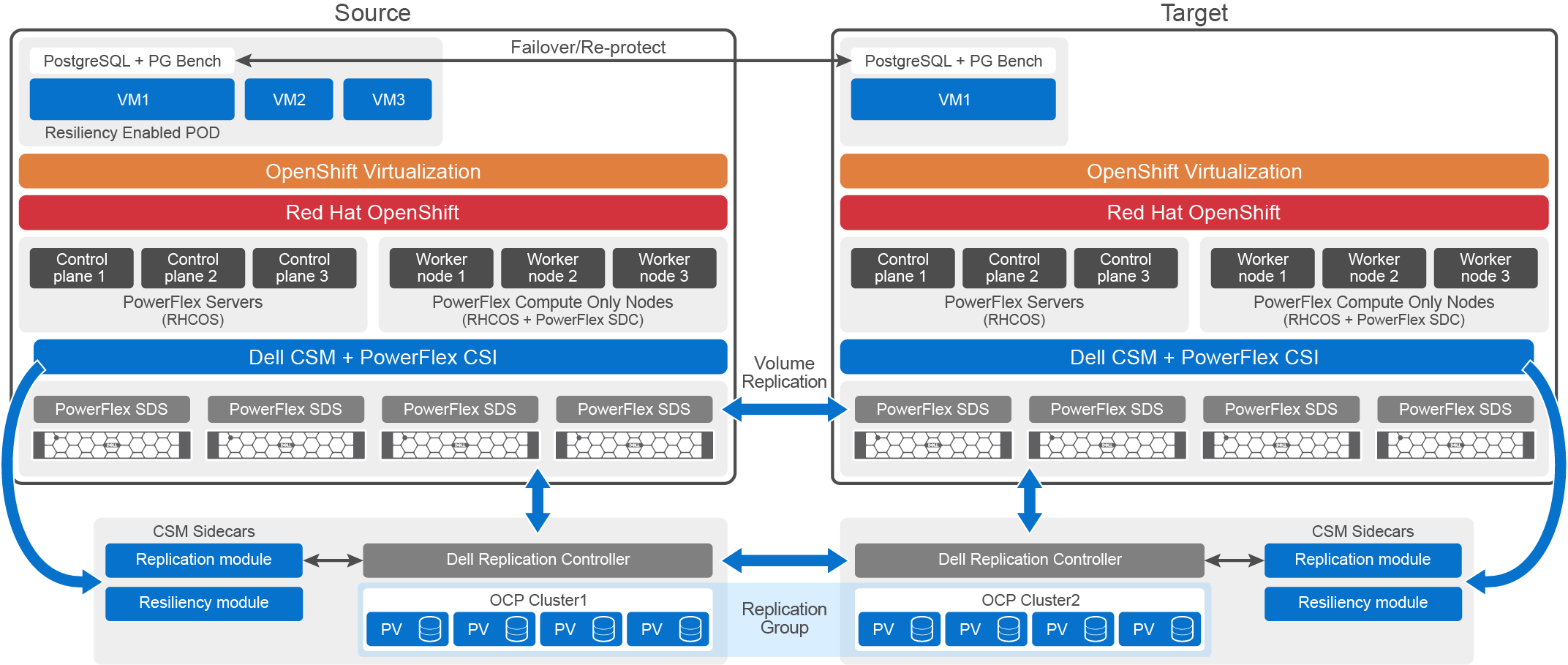
This solution describes the design and implementation of high availability and disaster recovery of VMs running on the OpenShift Virtualization platform with PowerFlex storage using PowerFlex CSM. The VMs are protected at the OCP cluster level using the PowerFlex CSM Resiliency module. Site-level recovery of the VMs is achieved using the PowerFlex CSM replication module.

Solution design

Figure 4. Logical architecture diagram of PowerFlex CSM Resiliency and Replication on OpenShift Virtualization.
Diagram comparing source and target system architectures for data replication and failover protection. It highlights components like PostgreSQL with PG Bench, OpenShift Virtualization, Red Hat OpenShift, Dell CSM with PowerFlex CSI, and replication modules, showing volume and replication group flows between PowerFlex nodes and OCP clusters. AI-generated content may be incorrect.

This architecture is designed by creating two identical systems representing the source system and the target system. The source system is an active system with the VM workload, and the target system represents the DR system.

The design and implementation of the systems represented in the preceding diagram consist of the following components.

  • Two OCP clusters, with one deployed on a source system and one on a target system. Each of these clusters is enabled with the OpenShift Virtualization feature. Both OCP clusters are deployed using the assisted installer with a configuration of three control nodes and three worker nodes. For the installation and recommended settings, see the Dell document Red Hat OpenShift Virtualization with Dell PowerFlex.
  • Two PowerFlex storage-only clusters, with one cluster running on the source system and one on the target system. The PowerFlex clusters are built using the PowerFlex Manager GUI. Two PowerFlex management platforms are used for this purpose. A single PowerFlex protection domain and a single storage pool are configured on each PowerFlex cluster. The PowerFlex storage pool topology consists of four SDSs with 10 SSD disks in each of the four SDS nodes.
  • Dell CSM is installed with the Replication and Resiliency modules. The PowerFlex CSI driver is installed with Replication and Resiliency sidecars enabled, for this purpose. The PowerFlex CSI driver enables dynamic provisioning and management of PowerFlex block storage for the stateful applications running on the OCP cluster. The CSM replication feature replicates the PVCs between source and target OCP clusters. The CSM resiliency feature provides cluster-level high availability for the pods during node failure.
  • VMs are created on the source and the target OCP clusters using the OpenShift web console to validate this solution. The PostgreSQL instance is installed on these VMs, and the replication-enabled PVCs are used to create data and log mounts of the PostgreSQL databases.
Note: The PowerFlex storage replication can be configured between two nonidentical clusters. See the Dell documents Dell PowerFlex: Introduction to Replication and Replication using Container Storage Module with Dell PowerFlex for details.

Network design

The following diagram shows the network design used in this solution:
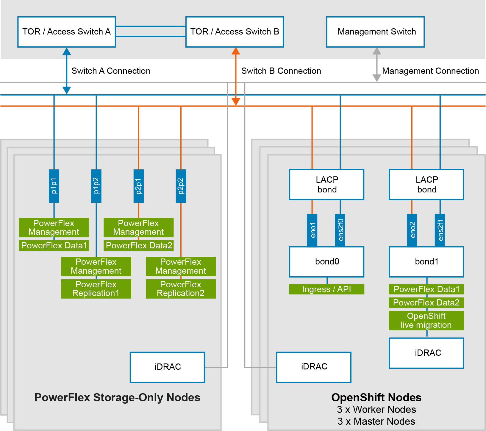
Figure 5. Network design of PowerFlex SO nodes and OCP compute nodes.
Diagram illustrating network connections between PowerFlex Storage-Only Nodes and OpenShift Nodes, showing management and data traffic flows. Key components include TOR/Access Switches A and B, Management Switch, LACP bonds, and iDRAC interfaces, with color-coded lines representing different connection types and labeled data paths for PowerFlex and OpenShift services. AI-generated content may be incorrect.

Each of the PowerFlex SO nodes and OCP nodes is attached with 2 x 25 GbE dual-port NICs. The node ports are trunked with the top-of-rack (TOR) switches. At the physical layer, two supported TOR switches are used for redundancy and load-balancing purposes. A peer link is configured on both TOR switches. VLANs are created to separate different traffic types on each node.

The VLANs configured for this solution are described in the following tables:

Table 3. Network details of PowerFlex SO node
Network type VLAN Configuration Purpose
PowerFlex Management 105 All 4 ports This VLAN (non-bonded) is used for PowerFlex management traffic.
PowerFlex Data1 151 Interface1 port1 This VLAN (non-bonded) is for PowerFlex data network traffic.
PowerFlex Data2 152 Interface2 port1 This VLAN (non-bonded) is for PowerFlex data network traffic.
PowerFlex Replication1 161 Interface1 port2 This VLAN (non-bonded) is for PowerFlex replication network traffic.
PowerFlex Replication2 162 Interface2 port2 This VLAN (non-bonded) is for PowerFlex replication network traffic.
Table 4. Network details of PowerFlex compute (OCP) nodes
Network type VLAN Configuration
Ingress API 105 VLAN 105 for OpenShift API/Ingress management.
PowerFlex Data1 151 Interface1 port1
PowerFlex Data2 152 Interface2 port2
Note: The network architecture described in this section is applicable to both source and target systems. For the OCP control and worker node-specific network configuration, see the Network architecture section from the Dell document Red Hat OpenShift Virtualization with Dell PowerFlex.

Configuring high availability and disaster recovery

Configuring high availability and disaster recovery

High availability for virtual machines running on the OpenShift Virtualization platform is enabled using the Dell Container Storage Modules (CSM) Resiliency feature, which provides node-level resiliency for VMs. Dell CSM replication capabilities provide system-level or site-level protection to support disaster recovery and minimize downtime during system-level or site-level failures. The detailed configuration and implementation steps for these capabilities are described in the following sections.

Note: For the configuration commands, see Appendix C - Configuring resiliency and replication.

Non-Protected components in PowerFlex CSM Replication

Dell PowerFlex CSI driver creates the persistent volumes (PVs) from Persistent Volume Claims (PVC) provided by users in their Kubernetes manifest YAML files. CSM Replication protects these PVs by replicating them at target volumes and managing operations such as replication synchronization and failover. It is important to note that CSM Replication maintains the same names for PVCs and PVs across the replication source and target. In addition, CSM creates the PowerFlex volumes at source system with the same name as the PVC name and at target system prefixes with the term replicated, making it even easier to manage and identify. However, keep in mind that the PowerFlex source and target volume IDs are unique to their system and do not match between source and target storage systems.

Although CSM Replication protects the PVs as explained above and provides an easy way to identify them on both source and target systems, this protection does not extend to the user application or VM deployment manifests. These YAML manifests and configuration files are stored outside the PVs and therefore are not replicated by PowerFlex CSM. As a result, if a disaster strikes and a replication failover operation takes place, the PVs will be available, but the manifests with the deployment instructions may not. It is therefore highly recommended that the user establish a process to store such files on an external NFS mount or a separately replicated volume to protect these files and make them available at the remote site if needed.

Prerequisites

The following prerequisites must be met to implement PowerFlex CSM Resiliency and Replication on OpenShift Virtualization.

  • Two PowerFlex storage-only clusters must be deployed with the PowerFlex replication enabled on them. These clusters must be in a healthy state and must be connected to each other by peering them in PowerFlex Manager.
  • Two OpenShift clusters must be deployed to represent the source system and the target system for replication. Each of these clusters must be connected to the PowerFlex storage system.
  • DNS and NTP are configured for name resolution and time synchronization across all OCP nodes and PowerFlex nodes.
  • OpenShift Virtualization is enabled on both OCP clusters. Select Operators > Virtualization in Assisted Installer during the OCP cluster deployment.
    Figure 6. Enabling virtualization from assisted installer.
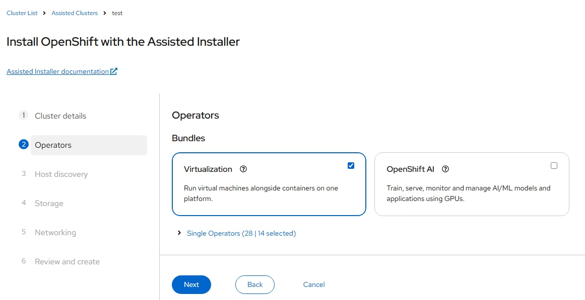
    Screenshot of the OpenShift Assisted Installer interface showing the "Operators" step in a multistep installation process. It highlights two operator bundles, "Virtualization" (selected) for running virtual machines alongside containers, and "OpenShift AI" (unselected) for managing AI/ML models using GPUs, with navigation buttons "Next," "Back," and "Cancel" at the bottom. AI-generated content may be incorrect.
    Note: OpenShift Virtualization can also be enabled using two additional methods—from the web console or from the CLI. See the Dell document Red Hat OpenShift Virtualization with Dell PowerFlex for details.

  • The PowerFlex CSI driver is installed on both OCP clusters. Dell CSM Replication and Resiliency modules must be enabled during the installation. These steps are described in Appendix B - Dell CSM replication and resiliency. Verify the PowerFlex CSM pod status to ensure the CSM modules are running in both OCP clusters.
    Figure 7. PowerFlex CSI pods state.
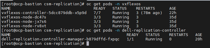
    Screenshot of a terminal window showing Kubernetes pod status for namespaces "vxflexos" and "n-dell-replication-cont." It lists pod names, readiness, status, restarts, and age, indicating all pods are running with minimal restarts and varying ages from 20 hours to 35 days. AI-generated content may be incorrect.
Note: This solution is implemented and tested in a Dell lab by deploying two PowerFlex storage-only clusters and two OCP clusters. See Lab details for more information. See the Dell documentation PowerFlex Rack with PowerFlex 4.x Field Implementation Guide for PowerFlex deployment details.

Configuring resiliency for a VM

The Dell CSM Resiliency module is designed to make the application or VMs running on the OCP cluster resilient during node failures. This module is deployed as a side car to the PowerFlex CSI driver.

The Resiliency module detects the pod failure during the node failure, control plane failure, or network failure, cleans up the pod artifacts from the failed nodes, revokes the PV access from the failed node, and recreates the pod on a healthy node by reattaching the PV.

After the Resiliency module is enabled, a pod must be labeled to make it resilient. Identify the pod on which the OpenShift Virtualization VMs are running, then label the pod to make it resilient as shown in the following screenshot.

Figure 8. Labeling the pod to enable the PowerFlex resiliency.
Labeling the pod to enable the PowerFlex resiliency.

Peering the PowerFlex clusters for replication

Two PowerFlex clusters are connected using the Peer Systems feature in PowerFlex Manager. The peer systems connect the source PowerFlex storage system and the target PowerFlex storage system. Follow the steps described below to peer systems.

  1. Exchange the PowerFlex system root Certificate Authority (CA) certificates between replicating clusters to protect from security attacks. On each system, create a certificate and send it to the other host in the replicated pair. Run the following PowerFlex CLI command on both systems:
    ssh <Primary MDM IP>
    scli --login --management_system_ip <PFMP Ingress IP or Domain Name> --username <PFMP UI username>
    scli --extract_root_ca --certificate_file /tmp/sys0.cert
  2. Manually copy the certificate to the partner cluster. Import the certificate on the partner system using a command in the following form:
    ssh <Primary MDM IP>
    scli --login --management_system_ip <PFMP Ingress IP or Domain Name> --username <PFMP UI username>
    scli --add_trusted_ca --certificate_file /tmp/sys0.cert --comment System-A
    Note: The certificate must be extracted and imported on both PowerFlex storage systems.

  3. Log in to the PowerFlex Manager of the source system and click Protection > Peer Systems > Add Peer System. Enter target system details in the page that opens, as shown in the following figure, and then click Add.
    Figure 9. Peering two clusters in PowerFlex Manager.
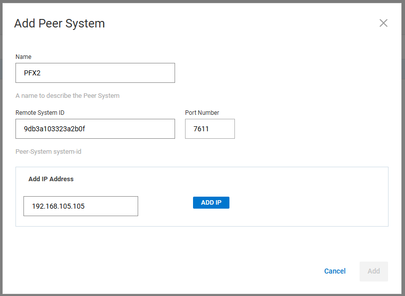
    Screenshot of a software interface for adding a peer system, showing fields for Name, Remote System ID, Port Number, and IP Address. The form includes a filled Name "PFX2," Remote System ID "9db3a103323a2b0f," Port Number "7611," and IP Address "192.168.105.105," with buttons labeled "ADD IP," "Cancel," and a disabled "Add." AI-generated content may be incorrect.
  4. PowerFlex cluster PFX2 is now peered with PowerFlex cluster PFX1.
    Figure 10. ‘Peer Systems’ in PowerFlex manager.

    Screenshot of a software interface titled "PowerFlex Manager" showing a table under "Peer Systems" with columns for Name, State, RCGs, Replication IP, and Version. The table lists one peer system named "PFX2" with status "Connected," no RCGs, replication IP "172.16.10.105," and version "3.6.0.0." AI-generated content may be incorrect.
    Note: PowerFlex clusters involved in the replication must be peered in both directions; therefore, repeat the above steps from the target system to add the source system. Provide the PowerFlex system ID in the Add Peer System screen. The system ID is displayed when you SSH to the Primary MDM and log in to the PowerFlex cluster using the scli command provided in the preceding step.

Configuring replication in a VM

In OpenShift Virtualization, virtual machines are provisioned through a Kubernetes‑native workflow using either the OpenShift web console or declarative YAML manifests. During VM creation, compute resources, networking, and boot sources are defined, while storage is attached by referencing Persistent Volume Claims.

When using Dell PowerFlex CSM replicated PVCs, a storage class with replication policy is selected, triggering PowerFlex to provision synchronized volumes across multiple nodes. The PVC is then attached to the VM as a virtual disk, providing persistent storage with replication-based resiliency. This integration enables seamless VM lifecycle operations such as restart or migration without data loss, leveraging PowerFlex replication for fault tolerance.

Creating PVCs

To validate this solution, two PVCs are created using the replication-enabled PowerFlex storage class. PowerFlex CSI manages this storage class and provisions PowerFlex volumes at the back end.
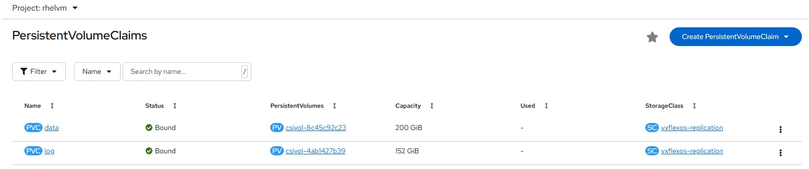
Figure 11. Two PVCs are created using replication enabled storage class.
Two PVCs are created using replication enabled storage class.

The following figure shows the PVC creation in the OpenShift console using the replication-enabled storage class vxflexos-replication, Access mode RWO and Volume mode Block.
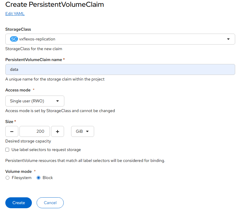
Figure 12. Creating a PVC in OpenShift console.
Creating a PVC in OpenShift console using the replication-enabled storage class “vxflexos-replication”, Access mode “RWO” and Volume mode “Block”.
Note: It is recommended to use Volume mode Block for the PVCs attached to VMs. This option provides the PowerFlex volumes as a raw block to the VMs. The PVC Access mode RWX must be selected to enable the VM migration feature for VMs on the OpenShift Virtualization platform. The PowerFlex CSI supports the Access mode RWX with the Volume mode Block for a nonreplicated PVC only. For the latest details on supported modes, see the Dell document for Container Storage Modules.

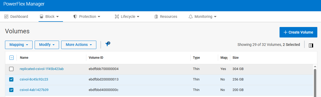
The PowerFlex CSI creates two PowerFlex volumes in the backend with the same name as the PV names. Verify this in PowerFlex Manager on the source system under the tab Block > Volumes.

Figure 13. Volumes in PowerFlex Manager of the source system.
Screenshot of PowerFlex Manager Volumes tab displaying a list of storage volumes with columns for Name, Volume ID, Type, Mapping status, and Size. Two volumes are selected, both labeled as Thin type, with sizes of 304 GB and 200 GB, and one volume mapped while the other is not. AI-generated content may be incorrect.

The Dell replication controller manager detects this new PVC creation request in the replicated storage class and creates a DellCSIReplicationGroup (RG)—a Kubernetes Custom Resource to enforce the defined policy within the storage class. RG is a logical PowerFlex construct that defines how volumes are replicated, placed, and protected across failure domains.

Note: The storage class is created using the yaml mentioned in the Appendix B - Dell CSM replication and resiliency section.
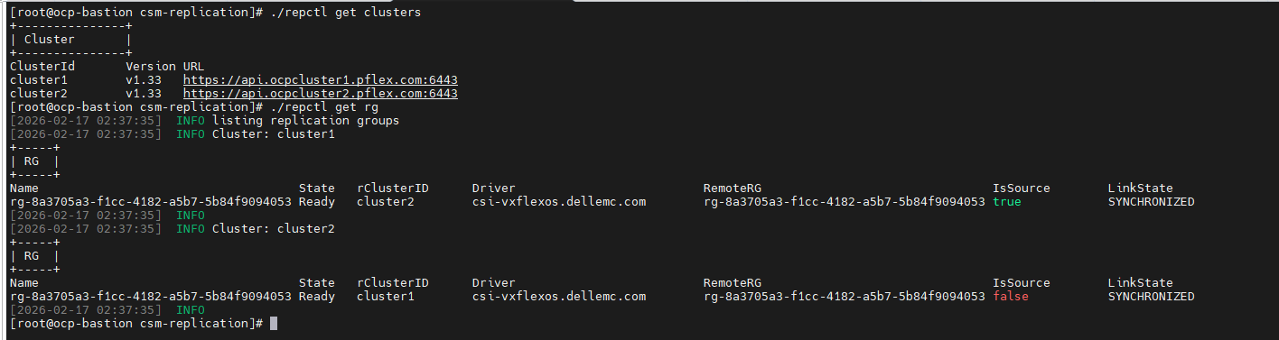
Figure 14. Replication group with the cluster details.
Command output showing details of replication groups and cluster status in a PowerFlex environment.

The CSM Replication controller replicates these two PVCs to the target OCP cluster. The PVC and PV are created with the same name on the target OCP cluster.
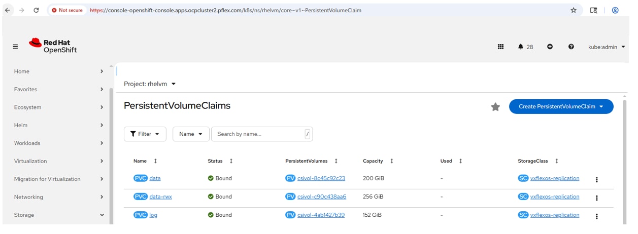
Figure 15. Replicated volumes on the target
Screenshot of a Red Hat OpenShift web console displaying PersistentVolumeClaims for a project named "helmv." The interface shows a table listing volume claim names, statuses marked as "Bound," capacities ranging from 152 GB to 255 GB, usage, and storage class labeled "reflexos-replication," with options to filter and create new PersistentVolumeClaims. AI-generated content may be incorrect.

In the backend, the PowerFlex volumes are replicated to the target PowerFlex cluster. Verify this in PowerFlex Manager on the target system.
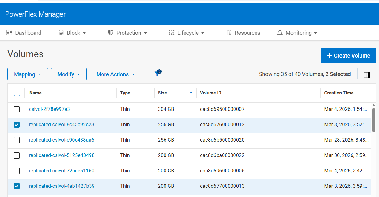
Figure 16. Replicated volumes in PowerFlex Manager of the target system
Screenshot of a PowerFlex Manager dashboard displaying a table of storage volumes with columns for Name, Type, Volume ID, and Creation Time. Two volumes are selected, both labeled "replicated-csivol" with sizes ranging from 200 GB to 304 GB, created in March 2026, highlighting volume management and creation details. AI-generated content may be incorrect.
Note: The names of the replicated volumes are prefixed with replicated, but volume IDs are different in the source and target storage systems.

Adding VM disks

In OpenShift Manager, create a VM by choosing Create > From InstanceType > rhel9 > U series (2 CPU, 4 GiB Memory).

Figure 17. A VM in an OpenShift console.
A VM in an OpenShift console.

Two disks are added using the PVCs created in the preceding section.

Figure 18. Two VM disks are attached to the VM.
A VM in an OpenShift console with two disks attached.

To create a VM disk, navigate to VM > Configuration > Storage > Disks > Add > Volume, then choose the replication-enabled PVC, Type as Disk, and Interface as VirtIO.
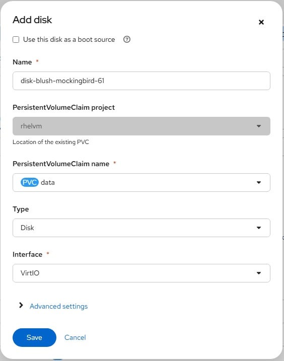
Figure 19. Creating a VM disk.
A VM in an OpenShift console with two disks attached.

Use cases

Use cases

The deployment is validated in a Dell lab by performing a set of use cases on a VM running on the OpenShift Virtualization platform with PowerFlex software-defined infrastructure. A PostgreSQL instance is deployed on this VM. A database workload of 100 GB is created using pgbench for this purpose. Three use cases are performed to demonstrate high availability and disaster recovery of a VM using PowerFlex CSI Resiliency and Replication capabilities. The details are described in the following sections.

Table 5. Test configuration details
Name Description
ocpcluster1 OCP cluster in the source system
ocpcluster2 OCP cluster in the target system
cluster1 A reference name given to ocpcluster1 in the RG.
cluster2 A reference name given to ocpcluster2 in the RG.
vm1 A VM running on a source system OpenShift Virtualization platform (in ocpcluster1).
vm A VM running on a target system OpenShift Virtualization platform (in ocpcluster2).
test1, test2 Two databases on a PostgreSQL instance, created for test purposes.
Data A PVC in the replicated storage class in PowerFlex, created in the source and the target systems. A storage disk is created in vm and vm1 with this PVC. This device is mounted to the data mount of the PostgreSQL instances running on ocpcluster1 and ocpcluster2.
Log A PVC in the replicated storage class in PowerFlex, created in the source and the target systems. A storage disk is created in vm and vm1 with this PVC. This device is mounted to the log mount of the PostgreSQL instances running on ocpcluster1 and ocpcluster2.
Note: All the commands and YAML files used while performing the use cases are given in Appendix B - Dell CSM replication and resiliency and Appendix C - Configuring resiliency and replication.

Use case 1: VM resiliency

This use case validates VM level resiliency during a node failure in an OCP cluster. The node on which the workload VM pod is running is brought down manually. The virt-launcher pod is recreated and the workload VM is successfully rebooted on the next available OCP worker node.

Execution

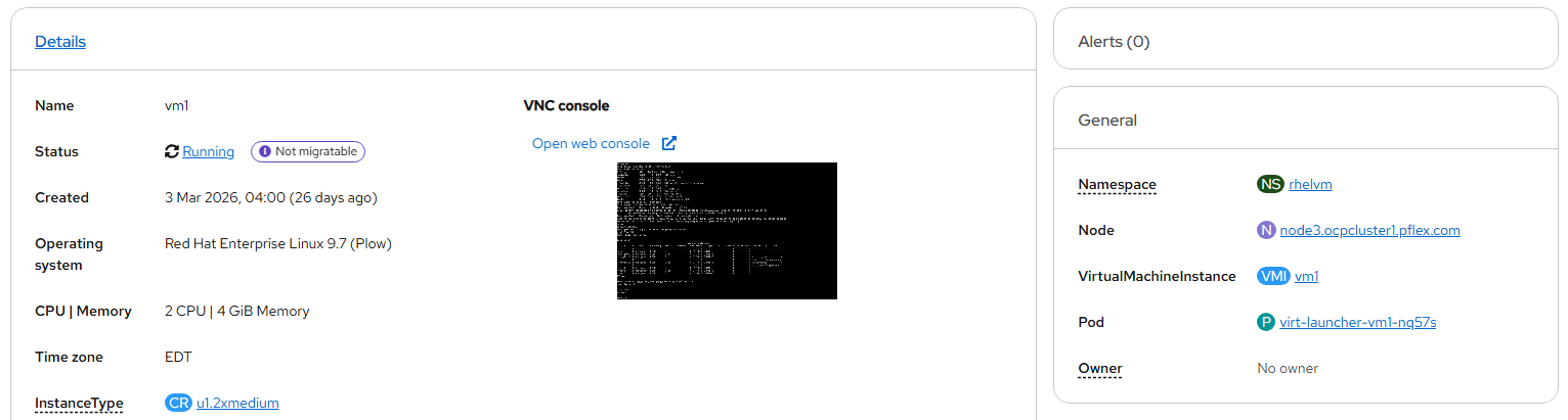
  1. Virtual machine vm1 running on the source OCP cluster, on OCP cluster node3, is used for validating the resiliency of the VM.
    Figure 20. vm1 is running on ocpcluster1, node3.
    Screenshot of a virtual machine details dashboard showing configuration and status information. Key elements include name "wtf", creation date March 3, 2023, operating system Red Hat Enterprise Linux 7, CPU and memory allocation of 2 CPUs and 4 GiB, and a VNC console with a black terminal window displaying command-line text. AI-generated content may be incorrect.
  2. The virt-launcher pod of vm1 is labeled with podmon.dellemc.com/driver=csi-vxflexos to enable PowerFlex CSI resiliency on this pod.
    Figure 21. The vm1 pod is labeled.

    Screenshot of a terminal window displaying Kubernetes pod status for "podman.dellcn.com" on nodes "ocpcluster1.pflex.com" and "ocp-bastion." It shows pod names, namespaces, readiness, status, restarts, age, IP addresses, and node assignments with all pods in "Running" or "Ready" states. AI-generated content may be incorrect.
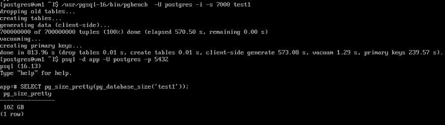
  3. Install a PostgreSQL instance and create a test1 database. Load the database with approximately 100 GB of sample data.
    Figure 22. PostgreSQL instance with test1 database on vm1.
    Screenshot of a terminal window showing PostgreSQL database operations including table creation, data insertion of 70 million tuples, and a query displaying database size. Key details include elapsed times for tasks, vacuuming process statistics, and a reported database size of 102 GB. AI-generated content may be incorrect.
  4. Node3 of the OCP cluster, where the vm1 pod is currently running, is put in maintenance mode.
    Figure 23. Node3 in ocpcluster1 is put in maintenance.

    Screenshot of a table displaying status, roles, points, memory, CPU, and filesystem usage for three nodes labeled "node1.copilot," "node2.copilot," and "node3.copilot." Each node shows "Ready" status with control-plane and master roles, varying memory and CPU usage, and creation dates of January 20, 2026. AI-generated content may be incorrect.
  5. A new virt-launcher-vm1-wwh5t pod is created for vm1 on node1.
    Figure 24. Pod is re-created on node1.

    Screenshot of a terminal window displaying Kubernetes pod information with columns for NAME, READY, STATUS, RESTARTS, and AGE. It shows multiple pods with statuses like Running and ContainerCreating, including details such as pod names, node assignments, and readiness indicators. AI-generated content may be incorrect.

Test conclusion

This use case validates node-level high availability for virtual machines using the Dell CSM Resiliency module on OpenShift Virtualization. When the OpenShift node hosting vm1 entered maintenance mode, the platform automatically recreated the virt-launcher pod on a healthy node and reattached the PowerFlex-backed PVCs without manual intervention. Restarting the PostgreSQL instance after recovery confirms that the data remains intact, demonstrating dependable VM recovery and persistent data protection during node outages.
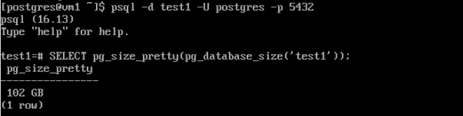
Figure 25. Database size in PostgreSQL after the pod recovery.
Screenshot of a terminal window showing a PostgreSQL command query and result. The query retrieves and displays the size of a database named "test1" as 102 GB, with command prompts and output text in white on a black background. AI-generated content may be incorrect.
Note: Application or database related downtime of approximately 3-5 minutes is expected due to VM reboot while using high availability for VMs running on OpenShift Virtualization using Dell CSM resiliency.

Use case 2: VM failover

This use case demonstrates a failover from the source system to the target system and then runs reprotect to synchronize the data between the new source and the new target systems. The ocpcluster1 (source) is deployed with a PostgreSQL instance. A test1 database is created with a data size of 102 GB using pgbench.

Execution

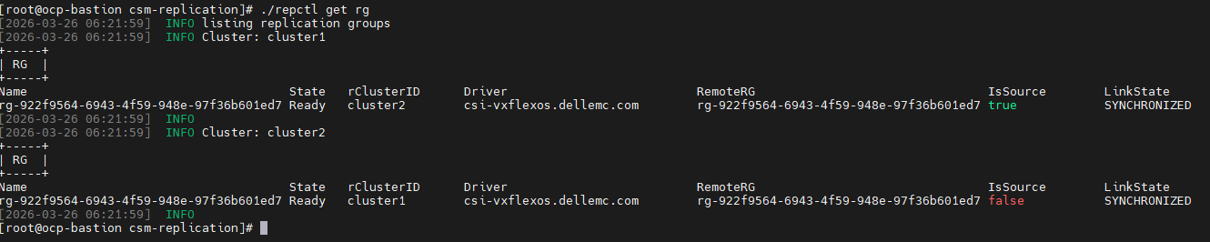
  1. The PowerFlex CSI replication is configured between ocpcluster1(source) and ocpcluster2(target). The data is synchronized between the source and the target OCP clusters.
    Figure 26. RG is showing the replication status.
    Screenshot of a terminal window displaying output from a command listing replication groups in a cluster environment. It shows details such as group ID, state, cluster ID, driver, remote site, source status, and link state, with key statuses including "SYNCHRONIZED" and "false" for source indicators. AI-generated content may be incorrect.
    Figure 27. The RCG view at the source PowerFlex Manager.
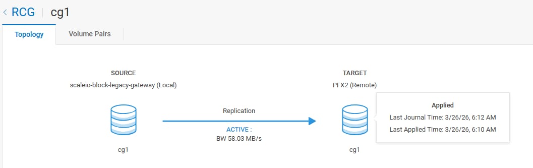
    Diagram showing replication setup between local source "scaleio-block-legacy-gateway" and remote target "PFFX2" for volume pair "cg1." Active replication is occurring with a bandwidth of 58.03 MB/s, and last journal and applied times are recorded as 3/26/26, 6:12 AM and 6:10 AM respectively. AI-generated content may be incorrect.
  2. Verify the test1 DB size in vm1 on ocpcluster1 before the failover.
    Figure 28. Test1 DB is created with a 102GB DB size in the source system.
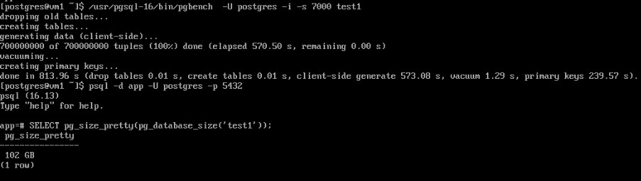
    Screenshot of a terminal window showing PostgreSQL database operations including table creation, data insertion of 7 million tuples, and execution of a SQL query to display database size. Key details include elapsed times for operations, vacuum process statistics, and a reported database size of 102 GB. AI-generated content may be incorrect.
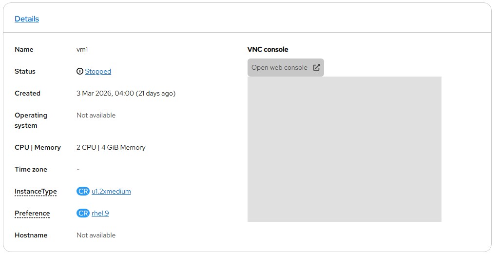
  3. Power off vm1 in ocpcluster1 before the failover, to ensure PVCs are not in use by any active workload.
    Figure 29. vm1 is stopped in ocpcluster1.
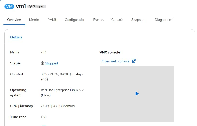
    Screenshot of a virtual machine management interface showing details for a VM named "vm1" with status "Stopped." Key information includes creation date, operating system (Red Hat Enterprise Linux 9.7), CPU and memory allocation (2 CPU, 4 GiB Memory), and a VNC console option with a play button. AI-generated content may be incorrect.
  4. The failover is triggered from the source OCP cluster to the target OCP cluster.
    Figure 30. Failover is triggered to target system.
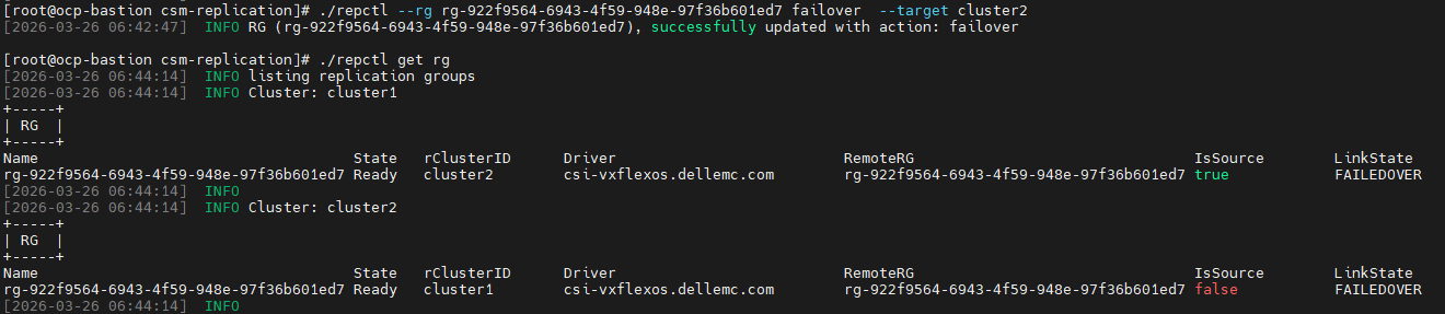
    Screenshot of a terminal displaying replication status for two clusters labeled cluster1 and cluster2. Each entry shows cluster ID, driver URL, remote ID, isSource status, and link state, with both clusters marked as ready and link state as FAILOVER. AI-generated content may be incorrect.
    Figure 31. Failed over to the target system from the target PowerFlex Manager.
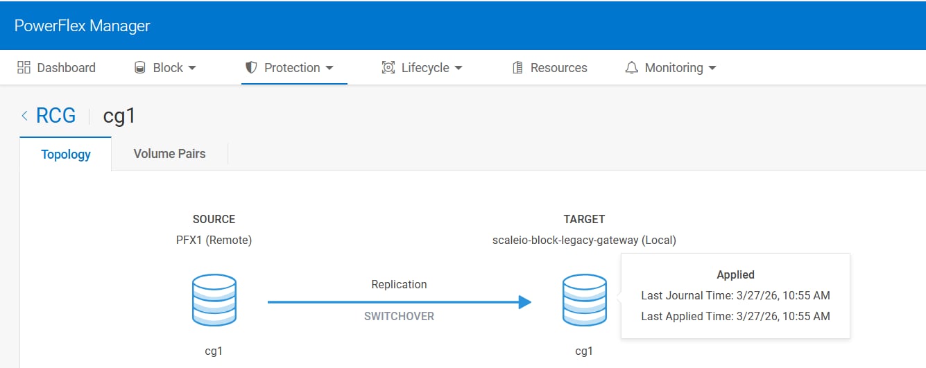
    Screenshot of a software interface showing a data replication topology between source and target storage systems labeled "cg1." The diagram highlights replication status with arrows and includes a tooltip displaying last journal and applied times for data synchronization. AI-generated content may be incorrect.
  5. Create a VM on ocpcluster2. Map the two replicated PVCs to this new VM to create the disks. Mount these disks to PostgreSQL data and log directories on the VM.
    Figure 32. Replicated PVCs are attached to the VM at the target ocpcluster2
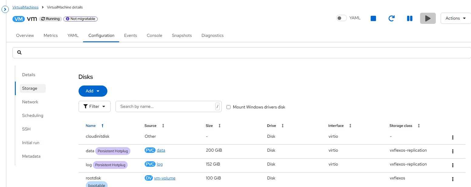
    Screenshot of a virtual machine storage configuration panel showing a table of disk details including name, source, size, drive type, interface, and storage class. The table lists four disks with sizes ranging from 100 GB to 752 GB, using interfaces like virtio and storage classes such as volflex-replication. AI-generated content may be incorrect.
    Figure 33. The disks are mounted to the VM.
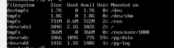
    Screenshot of a terminal window displaying disk usage statistics for various filesystems. It shows filesystem names, sizes, used and available space, usage percentages, and mount points, with notable usage of 59% on /pg/data and minimal usage on others. AI-generated content may be incorrect.
  6. Change the ownership and give access to the user postgres.
    Figure 34. Giving access to the mounts.

    Screenshot of a terminal window showing Linux commands for changing ownership and permissions of directories. Commands include 'sudo chown' to set postgres user and group for /pg/data and /pg/log, and 'sudo chmod 0700' to restrict access permissions on these directories. AI-generated content may be incorrect.
  7. Start the PostgreSQL instance on the target VM with these replicated mounts. The test1 DB is present with the same size of 102 GB.
    Figure 35. Test1 DB size in vm.
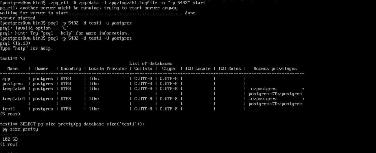
    Screenshot of a terminal window showing PostgreSQL commands and output. It includes a failed attempt to start the server, a list of databases with details like owner, encoding, and access privileges, and a query displaying the size of the "test1" database as 182 GB. AI-generated content may be incorrect.
  8. Perform a Reprotect RCG operation to resume replication between the new source system (cluster2) and the new target system (cluster1). This operation initiates volume synchronization in the reverse direction.
    Figure 36. Performing reprotect RG command.

    Screenshot of a terminal window displaying output from a command

Test conclusion

This use case validates site-level disaster recovery for virtual machines using the Dell CSM Replication module with PowerFlex storage. After initiating a controlled failover from the source OpenShift cluster to the target cluster, the replicated PVCs were successfully promoted and attached to the target VM. Bringing up the PostgreSQL instance on the target system confirms that the database and all associated data are fully preserved. After the successful failover, a reprotect RG is triggered to enable replication from the new source to the new target. This demonstrates that Dell CSM replication enables dependable VM failover with consistent data availability during site-level outages.

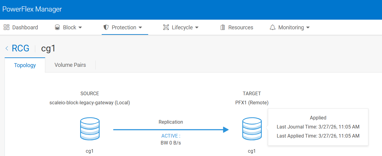
Figure 37. RG details with new source to new target replication.
Screenshot of a terminal displaying replicated input location groups for cluster1 with details including name, state, rclusterID, driver, remote, inSource, and linkState. Two identical entries show status as ready, driver as dcs.vxms.dellmem.com, and linkState as synchronized, indicating successful replication setup. AI-generated content may be incorrect.
Figure 38. PowerFlex Manager view at the new source system confirming the reverse replication state.
Screenshot of a software interface showing replication status between local source and remote target storage systems in PowerFlex Manager. It highlights an active replication with zero bandwidth usage and displays last journal and applied times as March 27, 2026, 11:05 AM. AI-generated content may be incorrect.

Use case 3: VM failback

This use case performs a failback to the original source system to set the replication in the original direction. Before setting the replication direction to the original path, confirm that the replication group (RG) status is healthy and the replication between the source and the target systems is functioning correctly.

Note: This test performs the RG failback using the unplanned option. The unplanned option is used during a real-time outage or disaster at the source system or at the primary site, and the unplanned flag is used to failover.

Execution

  1. Create a new test2 DB in the PostgreSQL instance running on the VM in ocpcluster2 (new source system).
    Figure 39. The test2 DB size in vm.
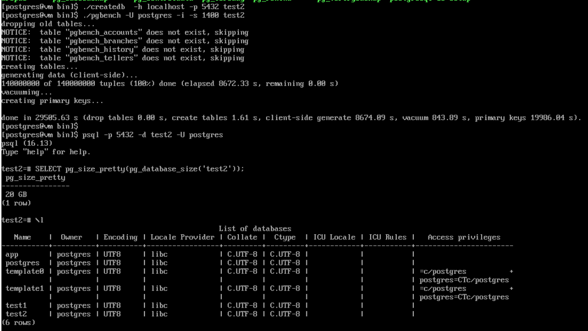
    Screenshot of a terminal window showing PostgreSQL database setup and query results. It includes commands for creating a database, generating data, and displaying database size and list of databases with details like owner, encoding, locale, and access privileges. AI-generated content may be incorrect.
    Figure 40. RG state before the failback.
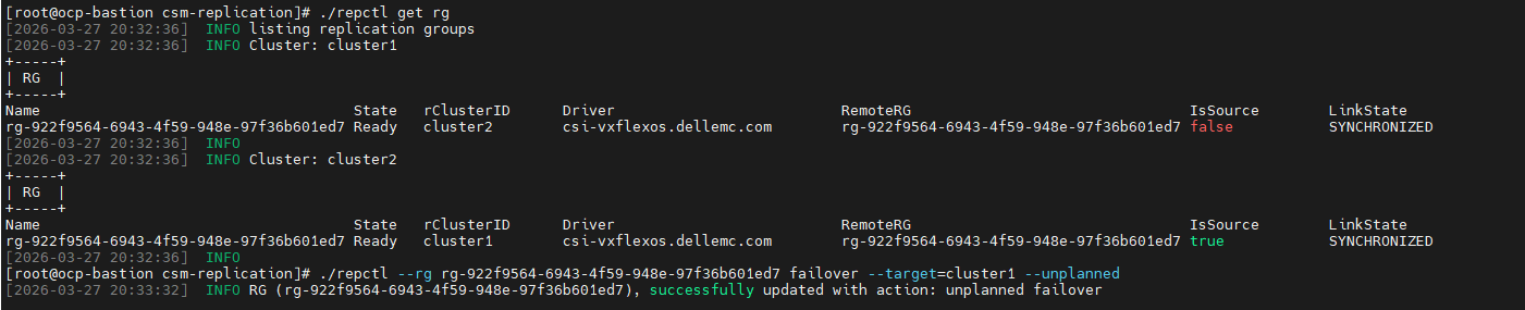
    Screenshot of a terminal window displaying output from a command related to replication status in a cluster environment. It shows two entries with details such as UUIDs, states (Ready), cluster IDs, drivers, remote RGs, link states (SYNCHRONIZED), and timestamps indicating successful updates and planned/unplanned failovers. AI-generated content may be incorrect.
  2. Power off the VM in ocpcluster2 or detach the replicated PVC from the VM if the source OCP cluster is accessible. Then perform the failover from ocpcluster2 to ocpcluster1.
    Figure 41. RG state after the failover.
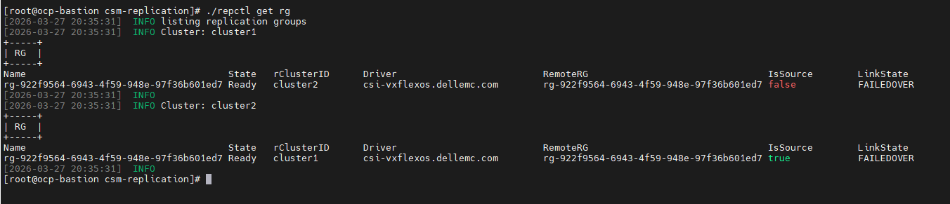
    Screenshot of a terminal displaying output from a command listing replication groups in an InfiniBox system. It shows two clusters with details including names, states (Ready and Faulted), drivers, remote IDs, and link states, highlighting one cluster with a failed link state. AI-generated content may be incorrect.
    Figure 42. RCG view in the original source system PowerFlex Manager.
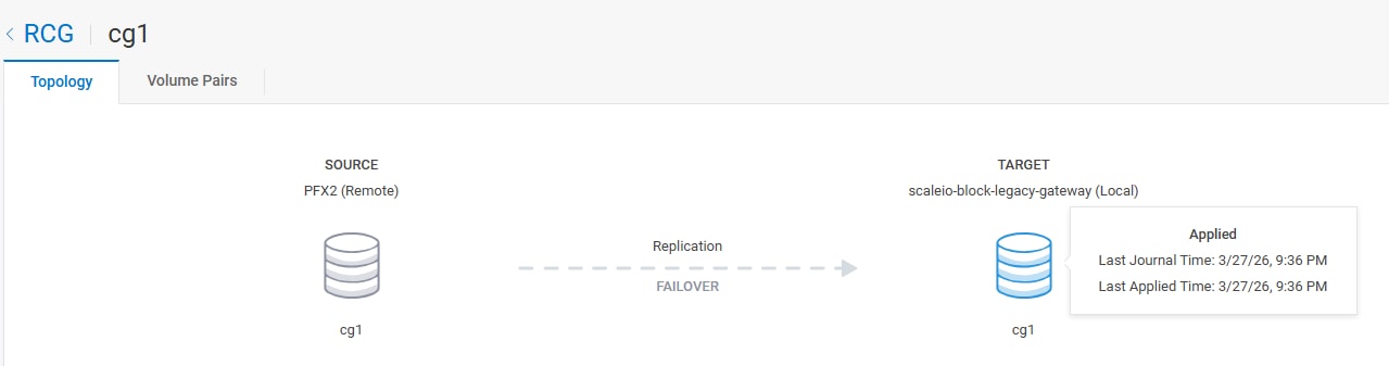
    Screenshot of a database replication topology showing source labeled "cg1" on PXF2 (Remote) and target labeled "cg1" on scaleio-block-legacy-gateway (Local). It highlights replication status with failover option and displays last journal time as 3/27/26, 9:34 PM and last applied time as 3/27/26, 9:36 PM. AI-generated content may be incorrect. AI-generated content may be incorrect.
  3. Start vm1 from the ocpcluster1 console and verify that the PVCs are attached.
    Figure 43. vm1 is running with PVCs attached.
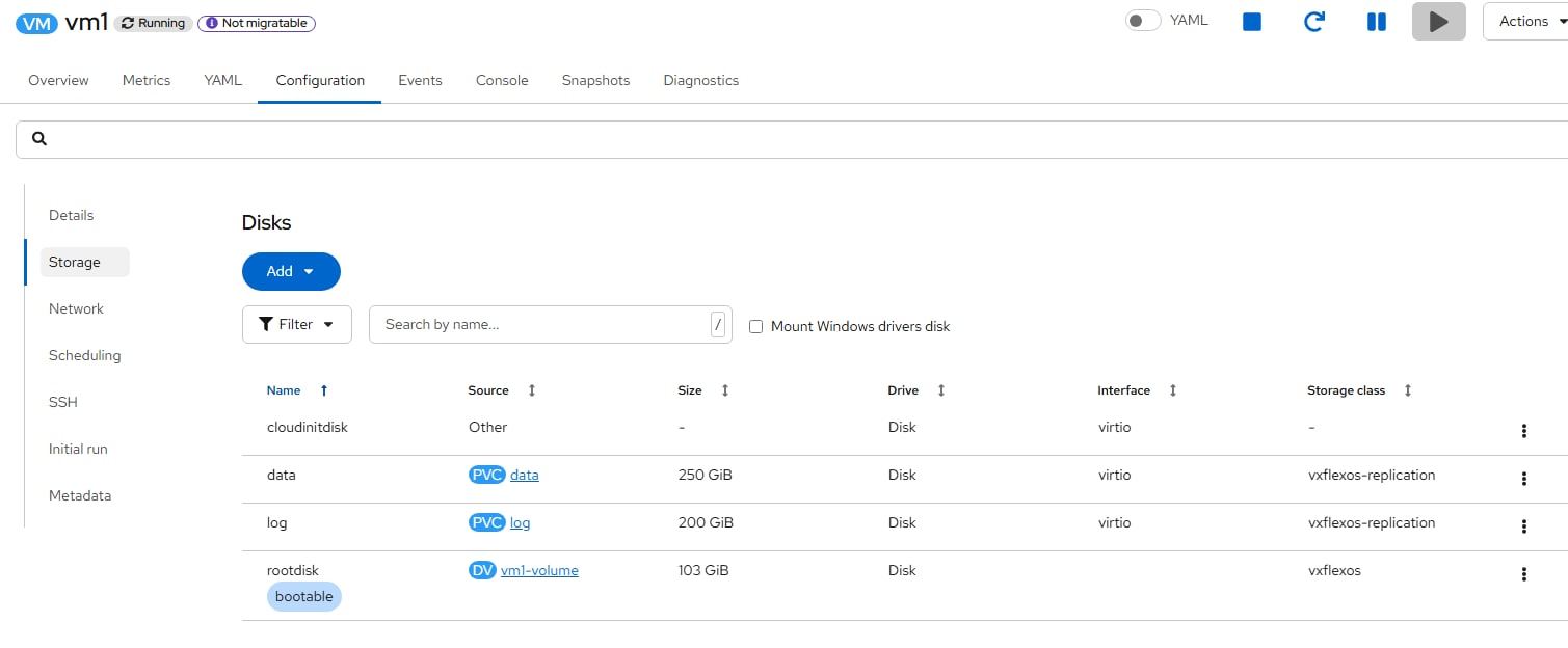
    Screenshot of a virtual machine management interface showing disk configuration under the Configuration tab. It lists four disks with names, types, sizes (ranging from 103 GB to 250 GB), interfaces (all virtio), and storage plans, highlighting one bootable disk and two disks using vreflex-replication storage. AI-generated content may be incorrect.
  4. Check the data and log mounts of the PostgreSQL instance and start the instance.
    Figure 44. Data and log mounts.

    Screenshot of a terminal window displaying disk usage statistics filtered for "pg" using the command "df -h | grep pg." It shows two mounted devices, /dev/vdb with 59% usage at /pg/data and /dev/vdc with 1% usage at /pg/log, with sizes and used space listed in human-readable format. AI-generated content may be incorrect.
    Figure 45. Test2 DB size in vm1 on ocpcluster1 after the failover.
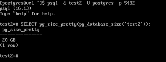
    Screenshot of a terminal window showing a PostgreSQL command performed to query the size of a database named "test2." The output displays the database size as 20 GB, with command prompts and connection details visible in white text on a black background. AI-generated content may be incorrect.
  5. Perform reprotect RG to resume replication in the original direction.
    Figure 46. RG state after the reprotect in the original source OCP cluster.
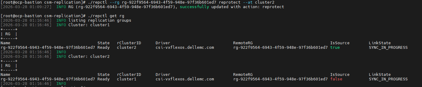
    Screenshot of a terminal window displaying status information for two clusters labeled cluster1 and cluster2. Details include replica set names, states (Ready and False), drivers (csi-vxflexos.dellemc.com), remote IDs, issue sources, and link states, with cluster2 showing an issue source marked as False and link state as IN_PROGRESS. AI-generated content may be incorrect.

Test conclusion

This use case validates the failback operation to the original source system using the Dell CSM replication module with PowerFlex storage. After completing reverse replication and initiating failover back to the original OpenShift cluster, the replicated PVCs were successfully promoted and reattached to the original VM. Restarting the PostgreSQL instance confirmed that all data, including updates made during the DR operation, was preserved. This demonstrates that Dell CSM replication supports dependable VM failback while maintaining data consistency and continuity across sites. The Reprotect RG operation is performed to synchronize the data and resume replication between the original source system and the original target system.
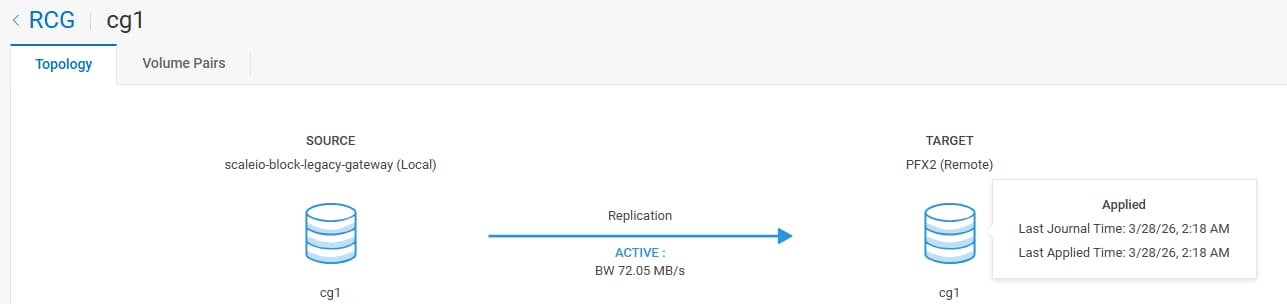
Figure 47. RCG in source system PowerFlex Manager shows the replication status.
Diagram illustrating data replication setup between local source "scaleio-block-legacy-gateway" and remote target "PF12." It shows active replication with a bandwidth of 7,206 MB/s, including timestamps for last applied times on both source and target. AI-generated content may be incorrect.

Conclusion

Conclusion

This solution delivers a unified, storage-native HA and DR framework for virtual machines running on OpenShift Virtualization with Dell PowerFlex. By combining policy-driven resiliency and replication through Dell CSM, it enables high availability, predictable disaster recovery, and operational simplicity across sites. The validated architecture and workflows provide a technical reference for designing and implementing VM data protection in hybrid OpenShift environments. To discover more, contact your Dell representative.

References

Dell Technologies documentation

Appendix A - Hardware and software components

Appendix A - Hardware and software components

Lab details

The following table lists the hardware and software components used in this:

PowerFlex storage-only nodes

Table 6. PowerFlex storage-only nodes - Hardware
Hardware Configuration
Server PowerFlex node R650
CPU 2 x 28 core, Intel(R) Xeon(R) Gold 6330 CPU @ 2.00GHz
Memory (GiB) 256 GB
NIC 2 x Mellanox ConnectX-5 Dual Port 10/25 GbE SFP28
Physical disks 10 x 1.6 TB, SSD SAS
Table 7. PowerFlex storage-only nodes - Software
Software Version
Operating system SUSE Linux Enterprise Server 15 SP6
PowerFlex SDS EMC-ScaleIO-sds-4.5.5001

PowerFlex compute/OCP nodes

Table 8. PowerFlex compute/OCP nodes - Hardware
Hardware Configuration
Server PowerFlex node R650
CPU 2 x 28 core, Intel(R) Xeon(R) Gold 6330
Memory (GiB) 256 GB
NIC 2 x Mellanox ConnectX-5 Dual Port 10/25 GbE SFP28
Table 9. PowerFlex compute/OCP nodes.- Software
Software Version
Operating system Red Hat Enterprise Linux CoreOS 4.20
OpenShift version 4.20.x (where x is the latest version)
PowerFlex SDC driver EMC-ScaleIO-sdc-5.0
PowerFlex CSI 2.16
Dell CSM 1.16
PostgreSQL 16

Appendix B - Dell CSM replication and resiliency

Appendix B - Dell CSM replication and resiliency

This appendix describes the steps to enable Dell CSM replication and resiliency.

  1. Install the repctl tool.
    wget https://github.com/dell/csm/releases/latest/download/repctl
    chmod +x repctl
  2. Add both OCP clusters’ admin configurations.
    ./repctl cluster add -f "/root/.kube/configocp1","/root/.kube/configocp2" -n "cluster1","cluster2"
  3. Inject the service account’s configuration into the clusters.
    ./repctl cluster inject
  4. Create the replication storage class using the following YAML.
    ./repctl create sc --from-config /yaml/powerflex_example_values.yaml

    cat /yaml/powerflex_example_values.yaml
    # Copyright © 2020-2025 Dell Inc. or its subsidiaries. All Rights Reserved.
    # Licensed under the Apache License, Version 2.0 (the "License");
    # you may not use this file except in compliance with the License.
    # You may obtain a copy of the License at
    # http://www.apache.org/licenses/LICENSE-2.0
    # Unless required by applicable law or agreed to in writing, software
    # distributed under the License is distributed on an "AS IS" BASIS,
    # WITHOUT WARRANTIES OR CONDITIONS OF ANY KIND, either express or implied.
    # See the License for the specific language governing permissions and
    # limitations under the License.
    sourceClusterID: "cluster1"
    targetClusterID: "cluster2"
    name: "vxflexos-replication"
    driver: "vxflexos"
    reclaimPolicy: "Delete"
    replicationPrefix: "replication.storage.dell.com"
    remoteRetentionPolicy:
    RG: "Delete"
    PV: "Retain"
    parameters:
    storagePool: # populate with storage pool to use of arrays
    source: "SP-1"
    target: "SP-New"
    protectionDomain: # populate with protection domain to use of arrays
    source: "PD-1"
    target: "PD-New"
    arrayID: # populate with unique ids of storage arrays
    source: "d3010358a804480f"
    target: "9db3a103323a2b0f"
    rpo: "60"
    volumeGroupPrefix: "csi"
    consistencyGroupName: "cg1" # optional name to be given to the rcg
  5. Install Dell Container Storage Modules from the OpenShift console’s Operator Hub.
  6. Install PowerFlex CSI as described in the Dell’s CSM installation document. Edit csm_vxflexos.yaml with the following values while creating the Custom Resource ContainerStorageModule for PowerFlex.
    - name: replication
    enabled: true
    components:
    - name: dell-replication-controller-manager
    - name: "REPLICATION_ALLOW_PVC_CREATION_ON_TARGET"
    value: "true"
    - name: resiliency
    enabled: true
    Note: The latest PowerFlex SDC driver is installed automatically during the PowerFlex CSI deployment. The older SDC driver can be installed manually for the custom deployment. See the Dell Container Storage Modules Support Matrix for details.

Appendix C - Configuring resiliency and replication

Enabling resiliency for the VM

$oc patch vm vm1 -n rhelvm --type='merge' -p='{"spec":{"template":{"metadata":{"labels":{"podmon.dellemc.com/driver":"csi-vxflexos"}}}}}'
$oc get pods -A -l podmon.dellemc.com/driver=csi-vxflexos -o wide

Failover to target

$./repctl --rg rg-922f9564-6943-4f59-948e-97f36b601ed7 failover  --target cluster2

Failover to target with unplanned option

$./repctl --rg rg-922f9564-6943-4f59-948e-97f36b601ed7 failover --target=cluster1 –unplanned

Reprotect the RG

$./repctl --rg rg-922f9564-6943-4f59-948e-97f36b601ed7 reprotect --at cluster1

PostgreSQL installation

$sudo dnf install -y https://download.postgresql.org/pub/repos/yum/reporpms/EL-9-x86_64/pgdg-redhat-repo-latest.noarch.rpm
$sudo dnf -qy module disable postgresql
$sudo dnf install -y postgresql16-server

Mount related commands

$sudo mkfs.xfs /dev/vdb
$sudo mkfs.xfs /dev/vdc
$sudo mkdir /pg/data
$sudo mkdir /pg/logs
$sudo mount /dev/vdb /pg/data/
$sudo mount /dev/vdc /pg/logs/
$sudo chown postgres:postgres /pg/data/
$sudo chown postgres:postgres /pg/logs/
$sudo chmod 0700 /pg/data/
$sudo chmod 0700 /pg/logs

PostgreSQL related commands

#Starting the PostgreSQL to the replicated mounts
$sudo su - postgres
$/usr/pgsql-16/bin/pg_ctl -D /pg/data start
# creating the DB
$/usr/pgsql-16/bin/createdb -h localhost -p 5432 test1
# Loading the DB using the Pgbench for 100GB data
$/usr/pgsql-16/bin/pgbench -U postgres -I -s 7000 test1
#Connecting the DB
$psql -d test1 -p 5432 -U postgres