PowerScale: Best Practices for Semiconductor EDA Design Environments
Executive summary
Overview
This document provides best practices for configuring and managing Dell PowerScale™ scale-out NAS storage, powered by the OneFS™ operating system, in a semiconductor Integrated Circuit (IC) design environment, commonly known as Electronic Design Automation (EDA) or chip design. It includes best practices for aggregated EDA workflows, system tuning and data management strategies.
Revisions
|
Date |
Part number/ |
Description |
|
February 2020 |
H18076 |
Initial release |
|
April 2024 |
H18076.1 |
Updated all topics for all-flash platform |
We value your feedback
Dell Technologies and the authors of this document welcome your feedback on this document. Contact the Dell Technologies team by email.
Author: Phillip Yang, Yifan Zhang
Contributors: Balachandran Rajendran, Connor Lamalfa, Dave Tsao, John Cassidy, Lawrence Vivolo, Timothy Wright
Note: For links to other documentation for this topic, see the PowerStore Info Hub.>
Introduction
Overview
The past decades have brought incredible growth and innovation in the semiconductor industry. Moore’s Law can take credit for much of this innovation. Moore’s Law predicts that the number of transistors on a chip will double every 2 years (mainly by making individual transistors smaller). EDA workflows, used to design semiconductor chips, have evolved to address the challenges of growing chip size and increased manufacturing complexity that has resulted. Requirements for compute (performance) and storage (total TBs) have also tracked with Moore’s Law – with CPU performance and storage requirements doubling every two years.
Eight years ago, however, the laws of physics made it more difficult to shrink individual transistors – slowing down the evolution. Engineers adapted by changing focus from growing CPU performance to increasing total core count per CPU. Engineers also increased transistor count per chip by making the chips much larger. Engineers continue to find new ways to shrink transistors as well, though more slowly. The net of all this is that Moore’s Law continues, but chip complexity is growing faster, which directly impacts infrastructure. Currently, CPU core requirements continue to double every 2 years. But storage requirements quadruple. This change has uncovered a new performance bottleneck – storage.
Unfortunately, existing storage technologies, while able to accommodate the acceleration in capacity requirements, they have done so at the expense of storage performance. This change has effectively shifted the EDA tool performance bottleneck – historically CPU performance – to storage performance. This problem can be traced to legacy scale-up storage architectures, which have dominated the semiconductor design market for decades, yet remained fundamentally unchanged.
Today market leading organizations are taking a holistic approach to IT infrastructure, looking for any opportunity to improve performance. Many are migrating to Dell PowerScale, which invented the scale-out storage architecture. They are also leveraging smarter job schedulers that can share resources more effectively. Design teams are looking to AI as a tool to give them a competitive advantage. Though most EDA flows are NFS driven, CAD and IT teams are looking to object storage to leverage the S3 access, geo replication, and distribution capabilities of Dell ECS storage as well. For Moore’s Law to remain alive in the new decade, organizations must innovate across the complete stack including CAD design flow, engineering infrastructure, and IT. With time-to-market requirements always a priority, the need for high performance, scalable, enterprise-class, and globally distributed design infrastructure is of utmost importance.
PowerScale for EDA workloads
Dell PowerScale combines a scalable hardware platform with a parallel software architecture to optimize data storage for EDA workloads. PowerScale scale-out, network-attached storage (NAS) is a fully distributed, symmetrical system that comprises clustered storage nodes. The OneFS operating system unifies the memory, I/O, CPUs, and disks of the nodes to present a single, linearly scaling file system.
Adding nodes adds capacity, performance, and resiliency to the cluster, and each node can process requests from EDA compute grid clients, while taking advantage of the entire cluster's performance. The PowerScale architecture contains no single location for the data, no concept of a controller head and no RAID groups. The result is a highly efficient, scalable, and elastic architecture.
One problem with traditional, scale-up storage architectures, is that they create performance bottlenecks that deteriorate at scale. The controller is the primary bottleneck and attaching too much capacity to the controller can saturate it. Storage system bottlenecks can negatively affect job completion time for concurrent jobs, which can lengthen design cycles and time to market for a new chip. The distributed PowerScale architecture eliminates the single-head CPU saturation point of a controller. A large number of concurrent jobs, often resulting in substantial amounts of metadata operations, can run without saturating the storage system, shortening the time to market.
Traditional storage systems also use disk space inefficiently. The uneven utilization of capacity across islands of storage requires manual intervention to rebalance volumes across aggregates and to migrate data to an even level – work that increase operating expenses. The inefficient utilization also negatively affects capital expenditures because extra capacity must be set aside as storage overhead.
In contrast, OneFS evenly distributes data among a cluster's nodes to maximize storage efficiency. A PowerScale cluster continuously balances data across all the constituent nodes, conserving space and eliminating much of the capacity overhead that traditional storage systems require. The efficient utilization of disk space and ease of use allow PowerScale storage to reduce both capital and operational expenses.
Traditional storage systems also have multiple points of management. Each filer must be individually managed, and this management overhead increases the total cost of ownership and operation expense (OpEx). The lack of centralized management also puts organizations at a strategic disadvantage because it undermines their ability to expand storage to adapt to growing datasets and fluctuating business needs, which can increase time to market. Multiple volumes of data are presented to users, which must work within the limits of each volume. The OneFS architecture, on the other hand, presents data within a single volume, regardless of the number of nodes within the cluster. With its single namespace, PowerScale delivers a high return on investment by centralizing data management.
New advancements of 7nm, 5nm, and 3nm process nodes have introduced complex design challenges for chipmakers, specifically the growing needs for storage performance to meet shorter design cycles and time to market challenges. PowerScale scale-out cluster lets organizations adapt to complex storage requirements, add capacity and performance in cost effective ways without disruption, and reduce elapsed times for concurrent jobs.
This paper describes these benefits of PowerScale storage and provides best practices for configuring and managing PowerScale systems in a semiconductor electronic design automation (EDA) environment.
Dell Unstructured Data Solutions Overview
Overview
Unstructured data does not have any pre-defined format or organization and does not reside in a standard database. Structured data is easy to search quickly using standard business analytic tools. Searching unstructured data takes different techniques and tools and is more difficult due the myriad of data sources and types that could be involved. However, unstructured data makes up a growing proportion of total data generated and accounts for over 80% of all data stored. Unstructured data requires a different approach regarding storage, particularly in the electronic design automation (EDA) field in which data is primarily unstructured.
PowerScale
Dell PowerScale storage is a scale-out NAS platform designed to meet the data storage challenges of the unstructured data age. Unlike traditional scale-up storage, PowerScale storage can scale to multiple petabytes of data in a single volume. Fully distributed single file system eliminates the need for administrators to set up and manage multiple storage silos, each with their own sets of RAID groups, aggregates, volumes, mount points, and hot spots to manage. These issues, common with legacy, scale-up storage, can make storage very difficult and expensive to manage, but these problems disappear with PowerScale storage.
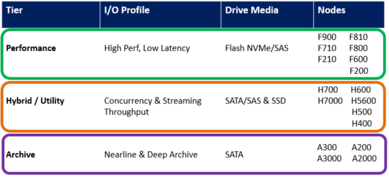
Figure 1. PowerScale hardware tiers and node types
PowerScale storage offers a variety of node types that are designed for each part of a typical EDA workloads. At the highest end of performance, the F910 model offers the highest performance thanks to its all-flash architecture. The PowerScale family also features hybrid node types with a mix of flash and spinning disks. Though these are common with other workloads, the vast majority of EDA workloads demand the highest performance, for which all-flash storage nodes are required. Finally, the A Series nodes offer the lowest cost per terabyte. The A300 model is designed for efficient back up and active archiving, while the A3000 model is designed for large, colder archives for long-term preservation.
ECS Enterprise Object Storage
Dell ECS is an enterprise-grade, cloud-scale, object storage platform. With ECS, any organization can deliver scalable public cloud services with the reliability and control of a private-cloud infrastructure. ECS provides comprehensive protocol support for unstructured—object and file—workloads on a single modern storage platform. Using ECS, organizations can easily manage globally distributed storage infrastructure under a single global namespace with anywhere access to content. ECS features a flexible software defined architecture that is layered to promote limitless scalability. Each layer is completely abstracted and independently scalable with high availability and no single points of failure. ECS also comes in a fully-integrated turnkey appliance that bundles software and Dell PowerEdge servers into an easily deployed object system. ECS is currently in its third generation of hardware appliances, the EX-Series, building on the legacy of the Centera and Atmos object storage platforms that predated ECS.
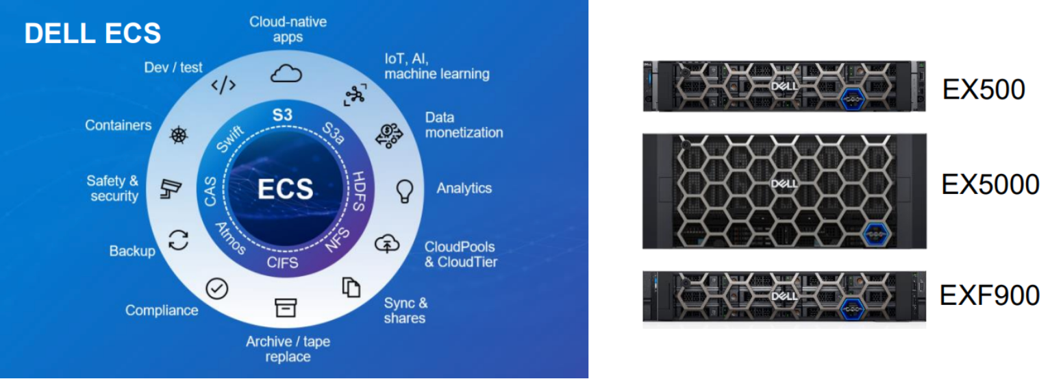
Figure 2. Dell ECS EX-Series
The ECS EX-Series is comprised of three unique hardware products: EX500, EX5000 and the all-flash EXF900.
ObjectScale
More and more, organizations rely on object storage as primary storage for demanding high-growth workloads including analytics, Generative AI and related cloud-native application development. Modern object storage options, including AWS S3, simplify the DevOps experience with a container-based, software-defined architecture backed by a popular automation platform, Kubernetes. But rather than using public cloud alone for the related tools and storage, many organizations are pivoting to a multicloud strategy—moving from “cloud to ground” with enterprise-class object storage on-premises in their data center.
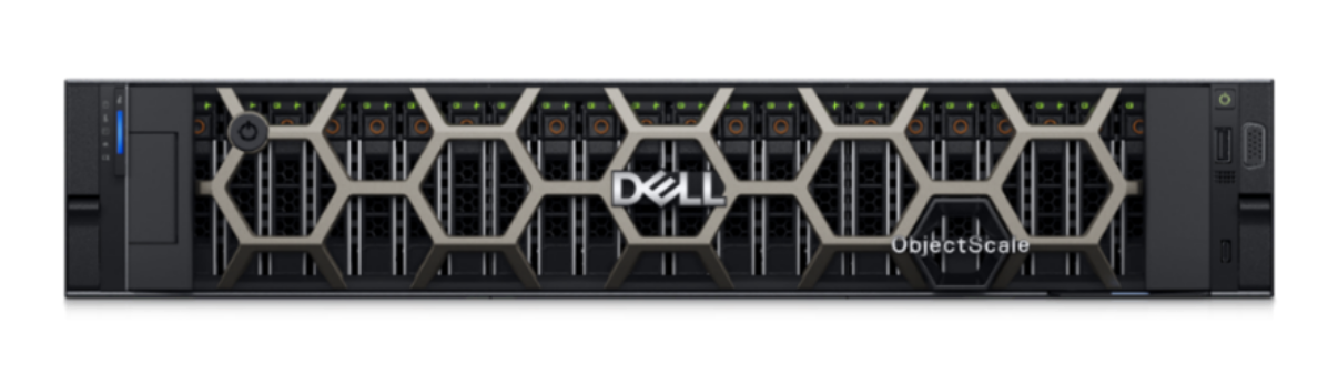
Figure 3. All-Flash Turnkey System: ObjectScale XF960
The ObjectScale XF960 is a powerhouse, all-flash appliance built on the latest 16th generation of Dell PowerEdge and integrated, deployed and supported as one by Dell Technologies. Flexible deployment options:
- As an Application - Dell manages the software, user deploy on Red Hat OpenShift
- Software Bundle - Dell manages the software and Kubernetes
- XF960 Appliance – Turnkey simplicity of a fully managed/supported Dell experience with powerful all-flash
SmartPools
SmartPools enables automatic migration of data up and down the different tiers within an PowerScale cluster – all within a single volume. Different node-types can be used for each tier to provide multiple tiers based on performance/capacity requirements. Data migration policy is configured by each customer, allowing for maximum flexibility and customization. This makes it easy for an administrator to optimize the performance and cost profile for every file. A common application for SmartPools in EDA is to automate migration of project data to lower-cost storage (including archive) after a project has tape-out. Moving data back from lower-cost storage can also be automated. This would be useful should a project need restored due to unexpected chip revisions, or to develop a next-generation chip. Behavior is controlled by policy, can be based on last time accessed (for example), and is fully configurable by the administrator.
CloudPools
CloudPools is an extension to SmartPools that enables tiering of data from a PowerScale to an ECS object storage, or to a public cloud, based on administrator-defined policies. This feature helps preserve the primary storage footprint by replacing old, infrequently accessed files with small reference or stub files. This frees up the storage space for newer, more frequently accessed data.
Note that most chip design workflows deal with large quantities of small files, which may be smaller than the stub files they would be replaced with. For EDA it is considered best to use PowerScale Hybrid/Archive model for infrequently accessed data.
Dell APEX Storage for Public Cloud
The Dell APEX Storage for Public Cloud brings enterprise-class storage to public clouds and offers operational consistency from on-premises to public cloud. Dell APEX Console simplify operations with consistent tools and experience across on-premises and public cloud environments.
The Dell APEX Storage for Public Cloud solution family includes APEX Block Storage for Public Cloud, APEX File Storage for Public Cloud, and APEX Protection Storage for Public Cloud.
EDA Workflow
Overview
This section describes the overall chip design workflow to help readers understand at a high-level stages of chip design. Understanding this workflow and the associated infrastructure to identify challenges that undermine the performance, efficiency, and scalability requirements for chip design. Historically, the EDA workflow is described, at a very high level, as consisting of the Front-end and Back-end flows though it is not uncommon for the flow to be broken into several high-level phases as shown in the figure 4 below. With each phase there are multiple EDA tools used for each phase by different role of designers.
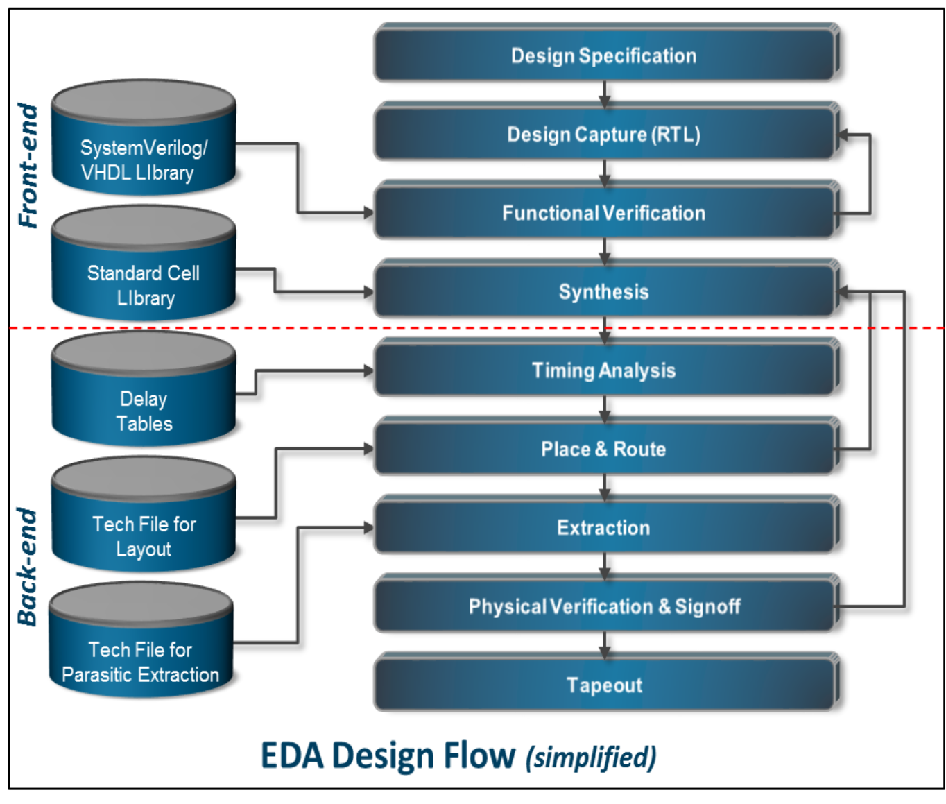
Figure 4. EDA Design Flow
Front-End
Each new chip design starts with design specification, where engineers define the precise parameters of the design – including functional features, power consumption, performance levels, physical chip size and more. Once the scope of the project is defined, engineers then build high-level architectural models of the design to help define the final architecture, verify that it meets performance goals, and begin building the verification environment. The design is then implemented using a specialized language (Register Transfer Language, or RTL) such as System Verilog or VHDL to capture the design in a format that can be synthesized to gates (groups of transistors). Transistors are one of the building blocks of semiconductor design. Typically, there is some overlap between high level modeling and RTL capture. Design verification at this stage is considered “functional verification” and occurs throughout the design cycle, including before and after design synthesis. Functional verification (simulation) checks that the design, as coded and synthesized, behaves as expected. (Ex: 1 + 1 = 2, not 3). For a complex design, hundreds of thousands of concurrent simulation “jobs” are typically run to save time. Functional verification does not check for physical attributes, such as heat dissipation, voltage variations and other electrical challenges. These are addressed in the back-end part of the flow.
Efficiency in creating, scheduling, and executing build and simulation jobs can reduce the time it takes to bring a chip to market. There are workflows used in design specification phase that generates an I/O-intensive workload when many jobs run in embarrassingly parallel way: EDA applications read and compile millions of small source files to build and simulate a chip design. A storage system manages the various design projects and files so that different users, scripts, and EDA applications can access the data. During the design verification stages, the data access pattern tends to be random, with many small files. Some of the workload requires high levels of concurrency because of the large number of jobs that need to run in embarrassingly parallel way, generating a random I/O pattern.
Back-End
During the back-end design phases, the data access pattern becomes more sequential. Some of the physical design implementation workflows for block level design tends to have a smaller number of jobs with a sequential I/O pattern that run for a very long period of time. The output of all the jobs involved in a chip's design phases can produce terabytes of data. Even though the output is often considered transient, and placed on scratch space, the data still requires the highest tier of storage for performance. Within the storage system, workflows tend to store a large number of files in a single directory, typically per design phase, amid a deep directory structure on a large storage system. The performance-sensitive project directories, including those for both scratch and non-scratch directories, dominate the file system and can become a bottleneck for legacy, scale-up storage solutions.
The directories contain source code trees, RTL files that define logic in Hardware Description Language (HDL), binary compiled files after synthesis against foundry libraries, and the output of functional verifications and other simulations. Typically, the RTL project directories that contain source code are minimal in size, while the project directories used for simulations dominate the overall capacity utilization of the storage system.
Client access consideration
This section introduces best practices regarding client access.
NFS versions
In typical EDA environments such as metadata intensive workloads, NFSv3 significantly improved performance over NFSv4.x.
NFSv3 is the ubiquitous protocol for clients accessing storage. This is due to the maturity of the protocol version, ease of implementation, and wide availability of client and server stacks. NFSv3 is widely adopted by EDA companies and recommended version to use.
NFSv4 introduced several enhanced features including improved security by using ACL. EDA company adopt both NFSv3 and NFSv4.x when the enhanced security features are required to secure company’s Intellectual Property (IP).
In general, NFSv3 is faster than NFSv4.x even though NFSv4 introduced some new feature to reduce protocol overheads.
NFS mount options
The mount options rsize and wsize specify the size of the data block size in bytes to be transferred at one time between the client and server. Setting a larger data block size would improve the performance. But be careful when changing these values; some older Linux kernels and network cards do not work well with larger block sizes. For most of modern systems, these settings are negotiated during mount and the server will specify the recommended settings. By default in OneFS, a rsize of 128 KB and wsize of 512 KB are advertised for NFSv3 Linux clients, but can be set as high as 1 MB. NFSv4.x defaults to 1 MB for both rsize and wsize.
NFS client uses the largest supported size by default. Setting the value too small on a client overrides the default value and can undermine performance.
For EDA workloads, the recommendation is to avoid explicitly setting NFS rsize or wsize parameters on NFS clients when mounting NFS exports directly or using the automounter. Instead, for NFSv3 clients, use the following mount parameters, either directly or in the Automounter map:
nfs rw,vers=3,tcp,hard,intr,retry=2,retrans=5,timeo=600
NFS over TCP
The advantage using NFS over TCP is that it works far better than UDP over unstable networks. When using TCP, a single dropped packet can be retransmitted, without the retransmission of the entire RPC request, resulting in better performance over unstable networks.
In addition, TCP will handle network speed differences better than UDP, due to the underlying flow control at the network level. When using UDP, if network speeds of the client and server are not identical, dropped packets and retransmissions might cause performance to be extremely slow when the faster entity tries to send data to the slower entity.
The overhead incurred by the TCP protocol will result in somewhat slower performance than UDP under ideal network conditions, but the cost is not severe, and is often not noticeable without careful measurement.
By default, the client will attempt to mount NFS export with TCP if supported, you can also use option proto=tcp to explicitly use TCP.
Note: NFS over TCP is integrated into all Linux kernel 2.4 and later.
Nconnect option
This mount option exists in all Linux distributions with kernel 5.3 or higher and can be set up to a limit of 16. It allows clients establish multiple TCP connections to a OneFS cluster node for a specific NFS version, as it can be used with NFSv3 and NFSv4.x with each individual version being tracked separately.
In EDA environment, if you are using 10 GB Ethernet or above from end to end, it’s highly recommended to improve the NFS performance with simple NFS mount option.
Usage: nconnect=<value>, value should be set to a number from 1 to 16. Setting this value too high will result in more degraded performance on low bandwidth networks.
Recommended value is 4 and measure results in a lab environment simulating a specific workload to ensure performance enhancements.
nfs rw,vers=3,tcp,hard,nconnect=4,intr,retry=2,retrans=5,timeo=600
MTU and Jumbo frames
A Maximum Transmission Unit (MTU) is the largest packet size or frame that can be sent along a link. The MTU is specified in octets and is used by TCP to determine the maximum size of a packet per transmission. A large MTU provides less overhead because packet headers and acknowledgments are not consuming space and bandwidth.
However, this could lead to retransmissions or drops if a hop does not support it. On the contrary, a small MTU is not as efficient as overhead increases with packet headers and acknowledgments.
Jumbo frames are Ethernet frames where the MTU is greater than the standard 1,500 bytes and a maximum of 9,000 bytes. The larger MTU provides greater efficiency because less overhead and fewer acknowledgments are sent across devices, drastically reducing interrupt load on endpoints.
In EDA environments, if you are using 10 GB Ethernet or above from end to end, jumbo frames are recommended for EDA workloads because the amount of data sent per message is far greater, reducing processing times and maximizing efficiency. The high-speed network may allow the larger frame sizes without encountering increased collision rates, particularly if you have set the network to full duplex.
While the general assumption is that jumbo frames provide performance advantages for all workloads, measure results in a lab environment simulating a specific workload to ensure performance enhancements.
For jumbo frames to take advantage of the greater efficiencies, they must be enabled end-to-end on all hops between endpoints. Otherwise, the MTU could be lowered, or packets could be fragmented. The fragmentation and reassembly affect the CPU performance of each hop, which affects the overall latency.
AUTH_SYS
NFSv3 clients use the AUTH_SYS (previously known as AUTH_UNIX) authentication method to pass credentials to the system. Using AUTH_SYS, clients send the user's ID (UID), primary group ID (GID) and up to 16 supplemental GIDs.
When an NFS client requests access from an NFS server it passes along three major pieces of information:
User ID (UID), One primary Group ID (GID), and up to 15 supplemental GIDs.
It will only ever send at most 16 GIDs between their primary GID and supplemental GIDs. This is by design in the NFS protocol and not a PowerScale specific limitation (see RFC 5531 and RFC 1813 for more information).
Since at different times the NFS client may send different supplemental GIDs, it is possible the client may at times not have any issues connecting. This also could result in a user being allowed access who is explicitly denied by group if the GID denied is not sent.
Default settings
Map Lookup UID is disabled by default.
Recommended settings
In EDA environments, project folders are secured by using multiple GID to control access from privileged employees or contractors only. User also belongs to multiple projects and have more than 16 groups (GID). They may be denied access if permissions are granted based on a group Id (GID).
This is by design in the NFS protocol and can be worked around with the Map Lookup UID option, which is disabled by default on exports.
This option ignores all GIDs sent with the UID and will then perform a lookup to the authentication providers to get the full list of GIDs that the user belongs to.
Update the tunable
The option can be enabled using the following command:
# isi nfs exports modify --id=<exportID> --zone=<accesszone> --map-lookup-uid=true
Load balancing and failover – SmartConnect
SmartConnect supporting dynamic NFS failover and failback for Linux and UNIX clients and SMB3 continuous availability for Windows clients. This ensures that when a node failure occurs or preventative maintenance is performed, all in-flight reads and writes are handed off to another node in the cluster to finish its operation without any user or application interruption.
During failover, clients are evenly redistributed across all remaining nodes in the cluster, ensuring minimal performance impact. If a node is brought down for any reason, including a failure, the virtual IP addresses on that node is seamlessly migrated to another node in the cluster. When the offline node is brought back online, SmartConnect automatically rebalances the NFS and SMB3 clients across the entire cluster to ensure maximum storage and performance utilization. For periodic system maintenance and software updates, this functionality allows for per-node rolling upgrades affording full-availability throughout the duration of the maintenance window.
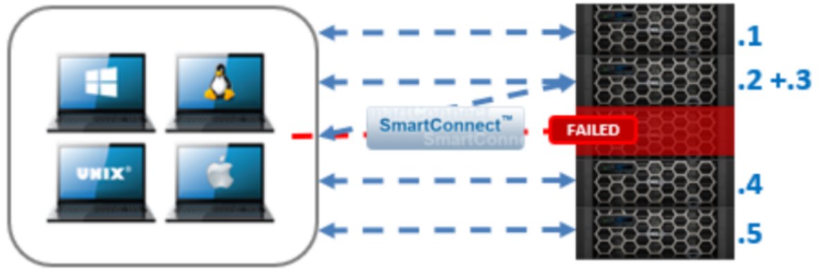
Figure 5. Seamless client failover with SmartConnect
SmartConnect also acts as a DNS delegation server to return IP addresses for SmartConnect zones, generally for load-balancing connections to the cluster.
SmartConnect load balances incoming network connections across SmartConnect zones composed of nodes, network interfaces, and pools. The load-balancing policies are Round Robin, Connection Count, CPU Utilization, and Network Throughput. The most common load-balancing policies are Round Robin and Connection Count, but these policies might not apply to all workloads. It is important to understand whether the front-end connections are being evenly distributed, either in count or by bandwidth. Front-end connection distribution can be monitored with InsightIQ or the WebUI. Because each workload is unique, understand how each load-balancing policy functions, and test the policy in a lab environment before a production roll-out.
SmartQoS
OneFS 9.5 introduces a new SmartQoS performance management feature. SmartQoS allows a cluster administrator to apply an OPS ceiling or limit to specified workloads for business workload prioritization.
In EDA environments, IT team can track, limit and throttle resource thus prioritizing business-critical workloads to get more resource during tape-out. Also, IT team can identify and limit resource for some rogue process with high throughput consuming storage resource and network bandwidth.
SmartQoS performance management can provide:
- Is applicable to NFSv3, NFSv4, NFSoRDMA, SMB, and S3
- Enables IT infrastructure teams to achieve performance SLAs
- Enables throttling of rogue or low-priority workloads, thus prioritizing other business-critical workloads
- Helps minimize data unavailability events due to overloaded clusters
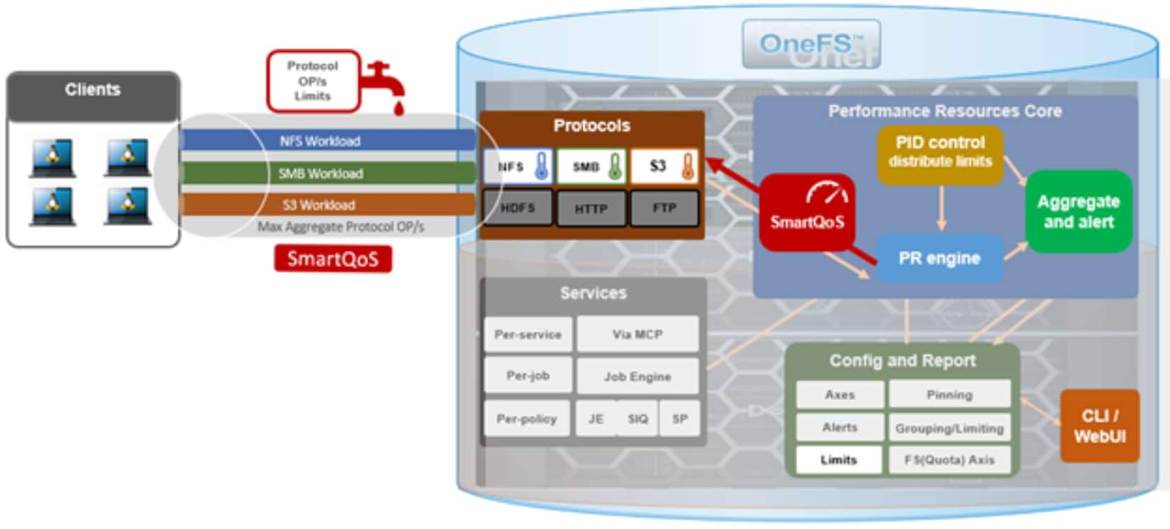
Figure 6. SmartQoS performance management
Metrics for SmartQoS monitoring resource are:
|
Category |
item |
|
Identification Metrics |
|
|
Transient Resources |
|
|
Performance Statistics |
|
|
Supported Protocols |
|
System Tuning
Overview
This section introduces several different configurable settings that are applicable to chip-design workflows, based on the collective experience of PowerScale customers, field and engineering resources. One may wonder why PowerScale is not configured with the appropriate settings out of the box. PowerScale is a scale-out clustered NAS system that caters to a wide variety of workflows in many different industries. The operating and performance requirements for specific industries like semiconductor, media and entertainment, healthcare, and others are quite different, and in some cases are contradictory in nature. For example, while the media and entertainment industry tend to have serialized workloads focused on larger files, semiconductor computer-aided design workflows are metadata intensive, and have a mix of mostly small and large file sizes. The flexibility of OneFS allows it to be tuned for specific, predominant workflows, and together with the family of different node types available, a cluster can be configured to deliver optimized performance throughout the EDA workflow.
Some settings may represent a tradeoff, such as space efficiency over performance, or require adhering to business needs such as prioritizing data protection at the expense of some performance. One should first gain a good understanding of the tunable and weigh its effect on the workloads on the cluster before making changes. It is highly recommended to test the settings in an isolated environment and engage with account resources for recommendations and/or any questions.
Semiconductor chip design workflows have dependencies on the entire infrastructure including compute client (including CPU/memory/NIC), OS, EDA tools and libraries, job scheduler, mount options, networking speed and configuration, authentication providers (NIS, LDAP, AD), name services, and much more. When framing any test, it is best practice to take a holistic approach that accounts for these environment variables and nature of the workflows hosted on the cluster.
Dell recommends that a test environment be maintained that includes all client OS versions in use. Having the ability to test various EDA tool and libraries versions, and job scheduler in an isolated environment, can be helpful in debugging issues.
The OneFS configuration settings listed in the following subsections are recommended for general EDA environments.
Note: The settings presented have been divided into three levels: basic, advanced, and expert. The expert level settings should be performed only with the help of PowerScale support team personnel. The Dell systems engineer (SE) assigned to the account should be consulted first to ensure applicability and validation of the settings for the specific customer environment and workflows.
Basic Tuning
Access Time Tuning
When a file is updated on a file system, the access time is updated. A read operation on metadata turns into a write as well since OneFS must update the inode. The result is increased CPU and disk traffic on a given system.
OneFS allows configuration on the granularity of access time updates. Changing this setting to 1 day means that access time will only be updated if the file was accessed more than one day ago.
Default setting
By default, this is set to 24-hours.
Recommended setting
Access time should be set relative to the customer’s workflow requirement. In general, anything less than one day is not required since SmartPools does not run more than once per day by default.
If planning on using atime, the use of a 24-hour precision is recommended to prevent performance problems.
Update the tunable
Use the standard option in the WebUI to update this tunable.
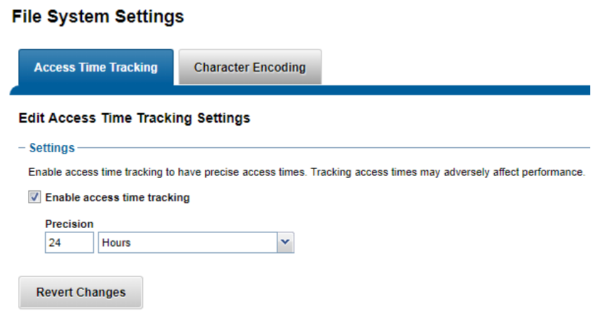
Figure 7. Access time tracking configuration
This metric that can be difficult to validate. The effect on the system results in less filesystem updates since metadata reads no longer need a metadata update. There may be a noticeable effect when observing disk activity before and after the change, but there are many attributes that affect the impact:
- How much the time granularity changed. If it was reduced from 1 second to 1 day, there should be a large change.
- The number of metadata read operations. These operations no longer need a disk write. The easiest way to look at this is to use InsightIQ to break down the operations by type.
32-bit file handle
NFS uses a structure called a file handle to uniquely identify exported files. When a client requests to access a file, the server constructs a file handle that identifies it. From this point on, this identifier is used in all communications between the server and the client to access that specific file. Some EDA tools especially need 32-bit file handles returned rather than the default 64-bit file handles.
With this setting at its default, some EDA applications may produce an error upon execution.
Default settings
This tunable is disabled by default.
Recommended settings
Enable this tunable for EDA and any other use case that requires this setting. This can be enabled globally, or by each export.
Update the tunable
On WebUI, Protocols > UNIX sharing (NFS) > Export Settings > Advanced settings > Return 32-bit file IDs.
Uncheck “Use default” and set to Yes. The default setting is No.
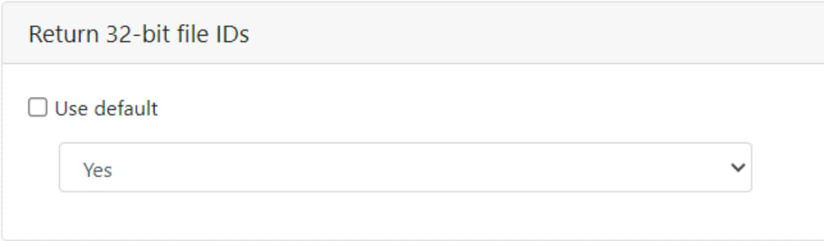
Figure 8. Return 32-bit file IDs setting
To enable this setting using the CLI, run the following command.
isi nfs settings export modify --return-32bit-file-ids=yes --zone=System
Note: Default export may cause an interruption of service for all NFS clients, requiring them to remount.
Job Engine
A logical inode (LIN) is a piece of metadata. Some OneFS system jobs have two types: one that processes at the block level, and one that processes at the metadata level. There is a setting that allows the job engine to force one level or the other.
The effect on running jobs can be substantial, and the difference between an AutoBalance and an AutoBalanceLin on a system with SSDs can be large as well. The time it takes to run some jobs can change from multiple days to a single day or less.
Default settings
OneFS 9.2 and later versions default to running the Lin-based version of the AutoBalance and FlexProtect jobs when these jobs start automatically, where appropriate.
Recommended settings
For systems with metadata acceleration (RO or RW, and not L3), use LIN-based jobs for optimal performance. Some jobs may be faster using LIN-based with L3 acceleration. This is because the job is changing its processing method from block-based to metadata-based. L2 and L3 hit rates for metadata may still be high enough to warrant the change.
The job engine should start LIN-based jobs, as shown in the following setting. (Auto does not perform this setting.)
isi_gconfig -t job-config jobs.common.lin_based_jobs
EDA design workflows use could benefit from using an EDA_OFF_HOURS schedule based on the typical off hours for your specific environment.
Update the tunable
isi_gconfig -t job-config jobs.common.lin_based_jobs=true
Parallel restriping
OneFS 9.7 introduces support for parallel restriping jobs, and hence the removal of the restriping exclusion set and its associated restraints. Instead, up to three restriping jobs can run simultaneously, if desired. This can allow services like SmartPools tiering to continue unabated, even in degraded cluster situations, such as during a FlexProtect drive rebuild.
Default settings
Off by default.
Recommended settings
More than one restriping job to run in parallel to shorten the restriping job to meet business SLAs. Depending on the situation, IT team can set parallel restriping to improve restriping time.
Update the tunable
For example, the following CLI command can be used to configure ‘Partial’ parallel restring support:
# isi job settings modify --parallel_restriper_mode=partial
Similarly, the Job Engine can be easily reverted to its default restripe exclusion set behavior, with only one restripe job permitted, as follows:
# isi job settings modify --parallel_restriper_mode=off
|
Setting |
Description |
|
Off |
Default: Legacy restripe exclusion set behavior, with only one restripe job permitted. |
|
Partial |
FlexProtect/FlexProtectLin runs alone, but all other restripers can be run together. |
|
All |
No restripe job exclusions. |
Number of active clients
By default, OneFS shows up to 256 active clients when using isi statistics command or in InsightIQ. In EDA environments, due to large compute grid, often more than 256 clients connect to each node. To accurately reflect this number, change the following parameter.
Default settings
By default, only 256 active clients are shown.
Recommended settings
Change the configuration to check for current setting and if necessary, change it allow 1024 active clients (maximum) to be reported by OneFS for NFS or SMB protocols.
sysctl isi.stats.client.<protocol>.max_clients
Update the tunable
sysctl isi.stats.client.<protocol>.max_clients=1024
Where protocol is nfs, nfs4, smb2, S3, cifs
Inline data reduction
Data reduction comes in various forms and includes techniques such as compression and deduplication. These techniques can be applied to data at various points in their storage life cycle, such as in real time as files are written from a client to storage, or after data has already been stored on disk.
In EDA environments, there are multiple duplicated project workspaces for each engineer working on the same project. It’s highly recommended to use inline data reduction on the project directories to save storage space.
Note: Scratch directories are exception because the nature of scratch usage. Usually, scratch directories are quota enabled for each engineer or project based so engineers frequently delete files after simulation jobs done to save space and free up quota.
Compression typically uses a lossless algorithm both to reduce the physical size of data when it is written to disk and to decompress the data when it is read back, while retaining full fidelity. More specifically, lossless compression reduces the number of bits in each file by identifying and reducing or eliminating statistical redundancy. No information is lost in lossless compression, and a file can easily be decompressed to its original form.
Deduplication differs from data compression in that it eliminates duplicate copies of repeating data. Whereas compression algorithms identify redundant data inside individual files and encode the redundant data more efficiently, deduplication inspects data and identifies sections, or even entire files that are identical and replaces them with a shared copy.
Both compression and deduplication are transparent to all applications that sit on top of the file system, including protocol-based services such as NFS, SMB, HDFS, and S3. The primary purpose of OneFS inline data reduction is to reduce the storage requirements for data, resulting in a smaller storage footprint, reduced power and cooling requirements, and a reduction in the overall per-TB storage cost. Real time, inline data reduction also helps to shrink the total amount of physical data written to storage devices. This can be beneficial for solid state drives (SSDs) and other media with finite overwrite limits, by reducing flash drive wear rates.
Default settings
In-line compression is enabled by default on new F810 clusters running OneFS 8.2.1 and later, on new H5600 clusters running OneFS 8.2.2 and later, on new F600 and F200 clusters running OneFS 9.0, on F900 clusters running OneFS 9.2, on H700/7000 and A300/3000 clusters running OneFS 9.2.1 and later, and F710 and F210 clusters running OneFS 9.7 and later.
In-line deduplication is enabled by default for new clusters running OneFS 9.4 or later. For earlier OneFS releases, inline dedupe is disabled by default.
Recommended settings
It is highly recommended to enable both inline compression and inline deduplication.
Update the tunable
Enable inline compression using below CLI command:
# isi compression settings view
Enabled: No
# isi compression settings modify --enabled=True
# isi compression settings view
Enabled: Yes
Enable inline deduplication using below CLI command:
# isi dedupe inline settings view
Mode: disabled
# isi dedupe inline settings modify –-mode enabled
# isi dedupe inline settings view
Mode: enabled
Assess mode.
OneFS inline data deduplication can be run in assess mode from the CLI with the following syntax:
# isi dedupe inline settings modify –-mode assess
Monitoring data reduction status.
The most comprehensive of the data reduction reporting CLI utilities is the ‘isi statistics data-reduction’ command. For example:
# isi statistics data-reduction
Recent Writes Cluster Data Reduction
(5 mins)
--------------------- ------------- ----------------------
Logical data 76.64M 99.71T
Zero-removal saved 0 -
Deduplication saved 0 76.44T
Compression saved 62.75M 1.81T
Inlined data 18.20M 4.85T
Preprotected physical 13.89M 16.61T
Protection overhead 27.78M 8.46T
Protected physical 41.67M 47.38T
Zero removal ratio 1.00 : 1 -
Deduplication ratio 1.00 : 1 4.28 : 1
Compression ratio 5.52 : 1 1.08 : 1
Data reduction ratio 5.52 : 1 4.65 : 1
Inlined data ratio 2.31 : 1 1.29 : 1
Efficiency ratio 1.84 : 1 2.10 : 1
--------------------- ------------- ----------------------
From the OneFS CLI, the ‘isi compression stats’ command provides the option to either view or list compression statistics. When run in ‘view’ mode, the command returns the compression ratio for both compressed and all writes, plus the percentage of incompressible writes, for a prior five-minute (300 seconds) interval. For example:
# isi compression stats view
stats for 300 seconds at: 2024-03-21 04:48:55 (1711010935)
compression ratio for compressed writes: 5.21 : 1
compression ratio for all writes: 5.21 : 1
incompressible data percent: 0.16%
total logical blocks: 8275
total physical blocks: 1554
writes for which compression was not attempted: 0.00%
From the OneFS CLI, the ‘isi dedupe stats’ command provides cluster deduplication data usage and savings statistics, in both logical and physical terms. For example:
# isi dedupe stats
Cluster Physical Size: 248.86T
Cluster Used Size: 48.39T
Logical Size Deduplicated: 79.73T
Logical Saving: 76.44T
Estimated Size Deduplicated: 103.39T
Estimated Physical Saving: 99.13T
Advanced tuning
Advanced tuning
The settings in this section should be modified in consultation with an SE as well as support personnel. EDA workloads can be varied in nature from front-end and back-end by chip design, various EDA tools used for chip design so every tunable may not be applicable to each scenario.
Endurant cache
Endurant cache (EC) was introduced in OneFS 7.1.1 and was aimed at reducing the latency of synchronous (immediate or stable write) small block random writes. The primary goal of this feature was to help with latency of VMware-type workloads on PowerScale storage.
By default, stable storage is written to disk, and a synchronous write requires the storage system to write to stable storage. Because the write is smaller than the Reed Solomon stripe, this causes a READ/WRITE/MODIFY penalty and impacts response time.
EC effectively works around this process by writing the small write to a small part on the journal that is protected. EC then has to de-stage these writes to disk over time. If multiple writes are issued to the same stripe, the de-staging of these writes is more efficient since the R/W/M penalty is only paid once.
An issue occurs when the EC space is not large enough. While EC helps with bursts, continuous traffic of small-block writes may cause it to constantly catch up, and this can result in lower performance compared to not using EC.
Default settings
EC can be managed on and off globally and tuned on or off per directory.
Recommended settings
The recommendation is to turn this off globally for EDA workloads.
Update the tunable
To disable globally, use below command.
isi_sysctl_cluster efs.bam.ec.mode=0
Cache prefetching
For read caching to be beneficial for reads, the cache must already contain data before it is requested. The storage system must accurately determine file access patterns and prepopulate the cache with data, and metadata blocks, before they are requested. OneFS uses two primary sources of information for predicting a file’s access pattern:
- OneFS attributes that can be set on files and directories to provide hints to the file system.
- The read activity occurring on the file.
This technique is known as prefetching, whereby predictively copying data into a cache before it has been requested mitigates the latency of an operation. Data prefetching is employed frequently and is a significant benefactor of the OneFS flexible file allocation strategy.
The most straightforward application of prefetch is file data, where linear access is common for unstructured data, such as media files. Reading and writing of such files generally starts at the beginning and continues unimpeded to the end of the file. After a few requests, it becomes highly likely that a file is being streamed to the end.
OneFS data prefetch strategies can be configured either from the command line or using SmartPools. File data prefetch behavior can be controlled down to a per-file granularity using the isi set command’s access pattern setting. The available selectable file access patterns include concurrency (the default), streaming, and random.
Metadata prefetch occurs for the same reason as file data, particularly benefiting scanning operations, such as finds and tree walks. To ensure that metadata keeps up with data block prefetching, OneFS 9.5 and later releases include both a metadata prefetcher and lock prefetcher. They are automatically enabled for concurrent and streaming data access patterns but remain inactive for random access where there is typically little benefit.
Default settings
Concurrency is the default setting for all file data.
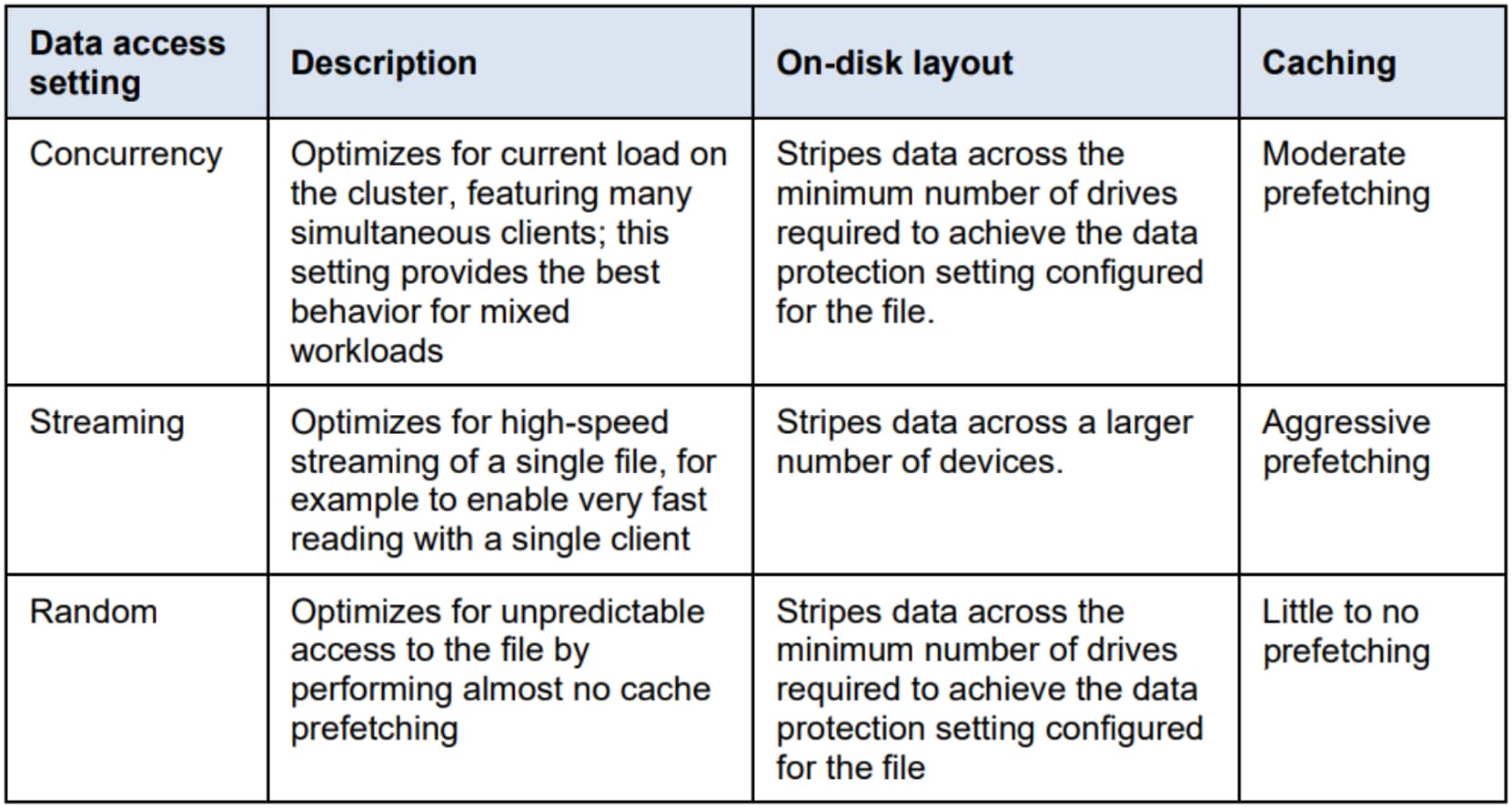
Figure 9. OneFS data access settings
Recommended settings
EDA workloads perform huge amount of concurrent I/O operations when thousands of jobs are running and accessing the same project folders.
Optimize for concurrent access (the default setting for all file data) is the recommended access setting for mixed EDA workloads.
Update the tunable
WebUI > File System > Storage pools > File pool policies > view/edit Default policy.

Figure 10. Set data access pattern optimization.
Direct Read and Direct Write
For streaming reads from low-latency SSD media, the cache benefit of prefetching is typically less than the overhead. To address this benefit, OneFS 9.5 and later releases automatically disable L2 cache prefetching for concurrent and streaming reads from SSD media, in a process known as Direct Read. However, L2 caching is still used when prefetching data blocks from spinning disk (HDD).
Similarly, OneFS 9.7 introduces Direct Write, also known as NCIO or non-cached I/O, which is a feature that targets the NVMe-based F series platforms and operates by bypassing cache to increase write throughput.
Writes to newly allocated blocks are identified and queued directly to the drives, by skipping the L2 cache and journal. This allows OneFS to better utilize the NVMe drives, reducing I/O access latency, and freeing up L2 cache and journal bandwidth for writes. And this will help in any streaming write or heavy sequential write workload.
Direct Write is analogous to the L2-bypass Direct Read functionality described above. Enabled by default in 9.7, it requires no license, is not user configurable, and, as such, has no CLI or WebUI interface.
Default settings
Direct Read – see above description.
Direct Write is enabled by default on OneFS 9.7 and above.
Recommended settings
EDA workloads can benefit from both Direct Read and Direct Write to reduce I/O access latency on all-flash F series platforms.
Note: OneFS 9.5 and above introduces Direct Read. OneFS 9.7 introduces Direct Write. For all-flash F series platforms.
For high capacity NVMe QLC drive, write speed is slower than high speed NVMe TLC drive. Consider turn off Direct Write to improve write performance and latency.
For high speed NVMe TLC drive, recommended to use Direct Write to improve write performance and latency.
Update the tunable
To disable Direct Write for high capacity NVMe QLC drive only, use below command.
# isi_sysctl_cluster efs.lbm.ncio.write.enable=0
Quota Tuning
Within OneFS, quota data is maintained in Quota Accounting Blocks (QABs). Each QAB contains a large number of Quota Accounting records, which need to be updated whenever a particular user adds or removes data from a file system on which quotas are enabled. If a large number of clients are accessing the file system simultaneously, these blocks can become highly contended and a potential bottleneck.
To address this issue, quota accounts have a mechanism to avoid hot spots on the nodes storing QABs. Quota account Constituents (QACs) help parallelize the quota accounting by including additional QAB mirrors on other nodes.
Default settings
By default, QAC ratio is set to 1.
Recommended settings
The following sysctl increases the number of quota accounting constituents, which allows for better scalability and reduces latencies on create/delete flurries when quotas are used.
Using this parameter, the internally calculated QAC count for each quota is multiplied by the specified value. If workflow experiences write performance issues, and it has many writes to files or directories governed by a single quota, increasing the QAC ratio (efs.quota.reorganize.qac_ratio) might improve write performance.
Update the tunable
The QAC ration can be changed to value 8 from the default value of 1 by running the following OneFS CLI command:
isi_sysctl_cluster efs.quota.reorganize.qac_ratio=8
Also, OneFS provides a CLI command that can restripe the QABs to improve their performance:
isi_restripe_qabs retune
This utility can be run either on demand or periodically to randomly redistribute QABs for all existing quotas. It does this by ignoring the default rebalance layout and running a retune layout strategy instead, thereby alleviating the performance impact from an imbalanced QAB layout.
Soft Quota
This setting is relevant when using soft quotas and being able to see the quota as configured and not seeing the capacity of the cluster as quoted space. However, this setting makes sense when soft quota enforcement is setup with a small grace period.
Under very heavy load where the write workload is consistently hitting the quota limits, using hard quotas may impact cluster performance.
Default settings
Use the below command to check the current value:
sysctl efs.quota.soft_containers
Note: The default may be a different value based on the OneFS version.
Recommended settings
The value of 1 is recommended for this setting. In conjunction with this setting, the recommended way to setup quotas is to use soft quotas with a short grace period of a few seconds instead of hard quotas.
Update the tunable
sysctl efs.quota.soft_containers=1
Coalescer multiwriter
This is a performance tuning option. EDA workloads tend to be highly concurrent. This setting dictates performance improvements for single-streamed workloads but may have a small performance penalty for some EDA workloads.
Default settings
To check the current setting, run the following command:
isi_sysctl_cluster efs.bam.coalescer.multiwriter
Note: The default may be a different value based on the OneFS version.
Recommended settings
The value of 1 is recommended in most EDA workloads. Specially on all-flash F series platform with latest OneFS version.
Update the tunable
# isi_sysctl_cluster efs.bam.coalescer.multiwriter=1
SmartConnect
This is applicable to NFSv3 environments, which comprises of most EDA workflows. This setting affects the nfs client-server behavior for certain non-idempotent filesystem operations where the server’s allocation of a delay or additional time allows for a graceful completion of an in-flight system call. This is not a tunable, but rather a configuration setting that should be applicable to all versions of OneFS.
Default settings
# isi network external view
Recommended settings
The values recommended is 1 for the rebalance-delay.
Update the tunable
# isi network external modify --sc-rebalance-delay=1
Asynchronous delete
This setting was introduced in OneFS version 8.2, and it is used with small-file EDA workloads to speed up the delete operations. It performs asynchronous deletes to significantly improve the latencies involved in delete operations.
This setting would allow faster deletes for many EDA workloads resulting in improved user job performance.
Default settings
By default, it is set to 1 which means it is disabled. Use the below command to check the current setting:
# sysctl efs.bam.async_delete_mode
Recommended settings
For EDA environments where performance of small file deletes are of importance, then the setting the async_delete_mode to 2 is recommended.
Update the tunable
# sysctl efs.bam.async_delete_mode=2
Expert-level tuning
Expert-level tuning
Do not apply the settings in this section without the guidance of an SE and a technical support personnel. Please open a Service Request (SR) prior to making any changes.
Additional NFS tuning
There are three settings related to client performance that are presented here as recommendations for EDA.
Default settings
To view the default settings for each setting run following commands:
# isi_gconfig registry.Services.lwio.Parameters.Drivers.nfs.nlm.QuarantineTimeSec
# isi_gconfig registry.Services.lwio.Parameters.Drivers.nfs.nlm.RpcIdleTimeout
# isi_gconfig registry.Services.lwio.Parameters.Drivers.nfs.SecurityCacheUidGidLruSize
Recommended settings
The values recommended are 30, 360, and 4000 respectively for QuarantineTimeSec, RpcIdleTimeout, and SecurityCacheUidGidLruSize settings above.
QuarantineTimeSec controls how long a client is put on a quarantine list if the client requests a deferred lock, and the cluster cannot contact the client’s NLM lock manager. Reduce the value to 30 or even set to 0.
RpcIdleTimeout controls how long before an NFS connection is considered idle. Set the value to 360 seconds.
SecurityCacheUidGidLruSize control users and groups to be cached on memory. Increasing the default value to 4000 to speed up users and groups lookup.
Update the tunable
# isi_gconfig registry.Services.lwio.Parameters.Drivers.nfs.nlm.QuarantineTimeSec=30
# isi_gconfig registry.Services.lwio.Parameters.Drivers.nfs.nlm.RpcIdleTimeout=360
# isi_gconfig registry.Services.lwio.Parameters.Drivers.nfs.SecurityCacheUidGidLruSize=4000
Data Tiering
Data Tiering
This section discusses best practices including tiering, SmartPools, archiving, and other topics.
For more detailed information on SmartPools and EDA, refer to the white papers and best practices documents listed in the references section. These documents delve into general best practices or practical implementation aspects of the PowerScale scale-out storage system in semiconductor chip design environments. For storage administrators, it is recommended to refer to additional documentation to cover other areas of PowerScale storage such as SmartConnect, SnapshotIQ, or SyncIQ to gain more comprehensive knowledge. Adhering to best practices in just one functional area, such as SmartPools, in isolation may not yield the desired and optimal cluster functionality.
Tiering
Tiering exists to achieve the business objectives out of storage system with minimum overhead.
The primary business objective usually is to avoid or reduce storage expenditure for non-business-critical data, driving the Total Cost of Ownership (TCO) lower.
- Another somewhat subtle driver for tiering is that IC chip designers are often more efficient spending their time on design work instead of cleaning up data. Due to the design data being inter-woven in complex directory structures and very large number of files, it could be time consuming to keep inactive data out of performance tier. Hence, as the accumulated data ages, it becomes increasingly difficult to assign clean-up responsibilities to designers or for IT to identify removable data. On top of that staff attrition makes it almost impossible to delete data over time.
- Yet another driver for tiering is tools and their versions. Chips are designed using specific tools, versions and associated libraries, so designers tend to save entire design projects to avoid tool mismatch or unavailability in future.
- Lastly, if a design must be re-spun in future, it is far easier if entire project was saved rather than just the source files.
While automated policy-based tiering helps in driving the TCO down, chip designers would like to improve their job runtimes regardless of location of data inside the cluster. Hence, depending on the amount of active vs semi-active vs inactive data, business archive policies, performance requirements, TCO requirements, and so on, effective tiering requires a careful consideration of how to mix node types in the cluster.
SmartPools data tiering
SmartPools enables a multi-tier architecture to be created using high-performance nodes with SSD for performance tiers and high-capacity SATA-only nodes for the high-capacity archive tier. For example, a file pool policy could move files from the performance tier to a more cost-effective capacity-biased tier after the wanted period of inactivity.
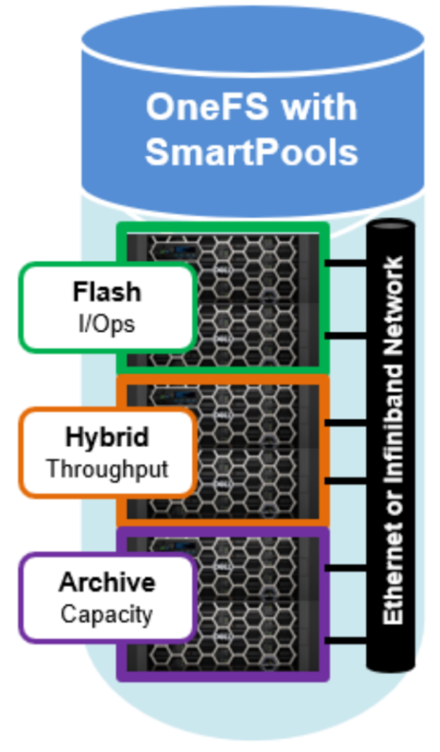
Figure 11. SmartPools tiering model
For more information about OneFS data tiering and file pool policies, see the SmartPools white paper.
SmartPools job in EDA environments
In EDA environment, the primary use case for SmartPools daily is to execute tiering from performance note to capacity node pool (or tier) or vice versa.
SmartPools job goes to every file, and the scanning portion of jobs can result in significant random impact to the cluster and lengthy execution times when cluster is hosting billions of EDA project data files, mostly text-based and very small file size.
To address this, there are SmartPoolsTree job and FilePolicy job.
SmartPoolsTree job goes to a tree of files instead of every files. If the file pool policies that you have defined are not changing the protection settings for a given path, then the SmartPoolsTree job can be run instead of SmartPools.
The SmartPoolsTree job can also be used to quickly set ingest policy on directories, execute a dry run, apply to directories only, or apply a policy recursively. This job can be scheduled to run at specific times or can be run manually.
For EDA environment, SmartPoolsTree jobs can be created if the SmartPools job is found to be taking too long to complete. Do not delete the file pool policies, rather, the schedule of SmartPools job can be changed so that it runs less frequently.
FilePolicy job provides a faster, lower impact method for applying file pool policies than the full-blown SmartPools job. In conjunction with the IndexUpdate job, FilePolicy improves job scan performance by using a ‘file system index’, or changelist, to find files needing policy changes, rather than a full tree scan. This dramatically decreases the amount of locking and metadata scanning work the job is required to perform, reducing impact on CPU and disk - albeit at the expense of not doing everything that SmartPools does. The FilePolicy job enforces just the SmartPools file pool policies, as opposed to the storage pool settings. For example, FilePolicy does not deal with changes to storage pools or storage pool settings, such as:
- Restriping activity due to adding, removing, or reorganizing node pools.
- Changes to storage pool settings or defaults, including protection.
However, the vast majority of the time SmartPools and FilePolicy perform the same work. Disabled by default, FilePolicy supports the full range of file pool policy features, reports the same information, and provides the same configuration options as the SmartPools job.
Since FilePolicy is a changelist-based job, it performs best when run frequently - once or multiple times a day, depending on the configured file pool policies, data size and rate of change.
CloudPools
CloudPools software provides a cloud storage tiering capability which is built on the SmartPools data management framework. CloudPools enables data to be stored in a cold or frozen data tier or archive, thereby taking advantage of lower-cost, off-premises storage.
File pool policies define which old or unused data on a cluster should be archived to the cloud. The supported cloud storage options include Amazon S3, Microsoft Azure, Google Cloud, Alibaba, Dell ECS, and OneFS to OneFS through the OneFS RAN (RESTful access to namespace API). CloudPools automatically optimizes and protects the transfer of data to cloud storage with the use of both encryption and compression.
Although file data is moved to remote storage, the files remain visible in the OneFS file system. CloudPools accomplishes this by retaining a local SmartLink (or stub) file, which is a pointer to the location of data in the cloud. CloudPools is also integrated with the other OneFS storage management and protection services including SnapshotIQ, SyncIQ replication, SmartQuotas, and NDMP backup.
Data protection
Data protection
The availability and protection of data can be usefully illustrated in terms of a continuum:
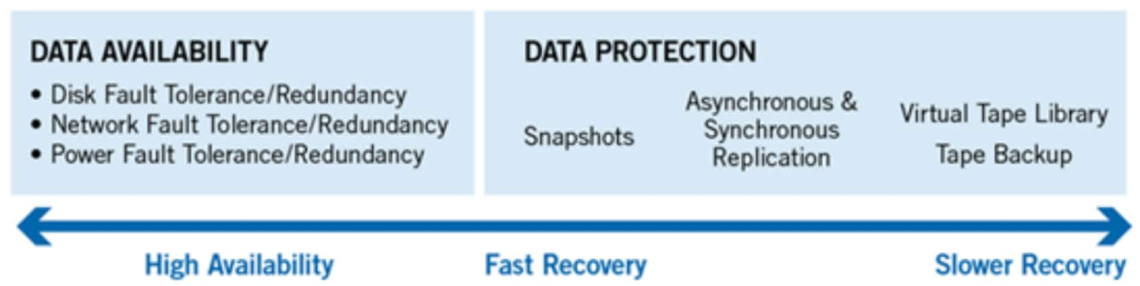
Figure 12. Data protection continuum
At the beginning of the continuum sits high availability. This requirement is usually satisfied by redundancy and fault tolerant designs. The goal here is continuous availability and the avoidance of downtime by the use of redundant components and services.
Further along the continuum lie the data recovery approaches in order of decreasing timeliness. These solutions typically include a form of point-in-time snapshots for fast recovery, followed by synchronous and asynchronous replication. Finally, backup to tape or a virtual tape library sits at the end of the continuum, providing insurance against large-scale data loss, natural disasters, and other catastrophic events.
Business Service Level Agreements (SLA)
It’s important to first understand which datasets the business (i.e., management) considers as worth protecting and for how long. Unlike finance industry, data protection and retention requirements in semiconductor are not governed by regulatory agencies. Often, this is driven by either customer contracts, or basic industry standard protection is assumed. Hence, some customers retain completed designs for 7, 10 or 15 years after final tape-out or a certain period after first production batch. Given the semiconductor storage requirements increasing exponentially with higher design densities, knowing what not to protect is critical so that data that does need protection can be adequately protected. For example, depending on the design practices employed, there may not be any need to protect the so called ‘scratch’ data. This could significantly change both architecture and budget requirements. Once you know all datasets that must be protected, Service Level Agreements (SLAs) can be reviewed to decide on retention periods, restoration time requirements, encryption, and so on. As such, the SLA itself can indicate what the business must protect.
What to protect?
The table below shows one way to organize the chip design data. It lends itself well in terms of data protection and management:
Table 1. Data classification for IC design data
|
Data Type |
Priority |
Protection scheme |
|
Project directories |
Business critical design data |
Short-term backup and snapshot, long-term backup |
|
Scratch directories |
Reproducible, transient data |
No protection or snapshot |
|
EDA tools and binaries |
Mostly read-only |
Weekly backup, no snapshot |
|
Foundational IP libraries |
Mostly read-only |
Weekly backup, no snapshot |
|
Home directories |
Business critical user data |
Daily backup and snapshot |
|
Others (QA, test, software repositories…) |
Business critical data |
Daily backup and snapshot |
Scratch data normally containing data that is transient in nature and used as a dumping ground for large log and results files generated during various design phases.
IT expects that for some reason this data is lost, it should not cause a delay in the design cycle. Therefore, the end-users must be well aware of the IT best practices and data protection policies offered. Even though some end-users want to keep portion of scratch data that can be reproducible but will take very long time to get results. In that situation, short-term snapshots can be configured for scratch areas depending on the business SLAs.
Data protection strategies
At the core of every effective data protection strategy lies a solid business continuity plan. All enterprises need an explicitly defined and routinely tested plan to minimize the potential impact to the workflow when a failure occurs or in the event of a natural disaster. There are several ways to address data protection and most enterprises adopt a combination of these methods, to varying degrees.
Among the primary approaches to data protection are fault tolerance, redundancy, snapshots, replication (local, geographically separate, or both), and backups to nearline storage, VTL, or tape.
Some of these methods are biased towards cost efficiency but have a higher risk associated with them, and others represent a higher cost but also offer an increased level of protection.
Two ways to measure cost compared to risk from a data protection point of view are:
- Recovery Time Objective (RTO): RTO is the allotted amount of time within a Service Level Agreement (SLA) to recover data. For example, an RTO of four hours means data must be restored and made available within four hours of an outage.
- Recovery Point Objective (RPO): RPO is the acceptable amount of data loss that can be tolerated per an SLA. An RPO of 30 minutes means that 30 minutes is the maximum amount of time that can elapse since the last backup or snapshot was taken.
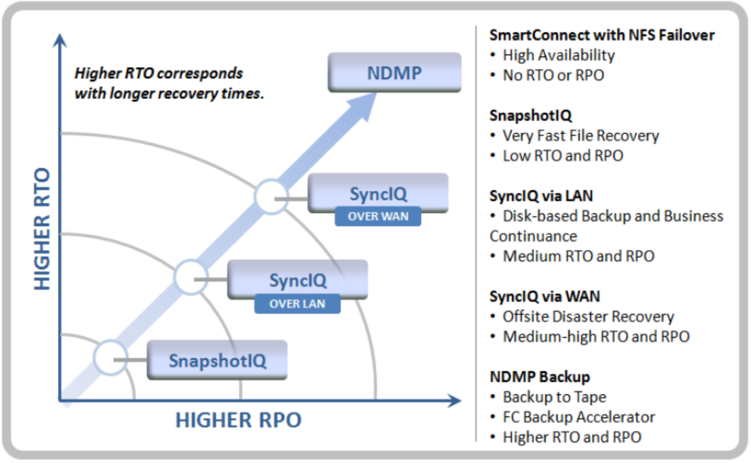
Figure 13. OneFS data protection technology alignment with protection continuum
Based on the table 1 above, short-term retention, which is usually based on snapshots is used for specific data sets to satisfy low recovery objective SLAs. For projects, and home directories, replication of data from the primary cluster to a target DR cluster, ideally located at a geographically separate location, is strongly recommended. NDMP backup to tape or VTL (virtual tape library) typically satisfies long-term high recovery objective, disaster recovery SLAs and any regulatory compliance requirements.
Below is a sample recommendation for different data types in semiconductor:
- Project area: Snapshots, replication, backups, and off-site storage
- Scratch areas: No protection beyond system fault tolerance configuration
- EDA tools, binaries: Snapshots, replication (for distribution), less frequent backups
- Libraries: Replication (for distribution), less frequent backups
- Home directories: Snapshots, backups, and off-site storage
- Other data: define policies based on business SLAs
OneFS offers the SnapshotIQ for snapshots, and SyncIQ for replication and backups to another PowerScale cluster. OneFS also supports NDMP protocol for both a 2-way and 3-way backup configuration. The Dell suite of products include backup solutions that can be engaged in the overall data protection architecture. In addition, there are a number of 3rd-party backup applications that can utilize the SnapshotIQ feature to backup data on to Dell ECS Object Storage platform, Virtual Tape Libraries, physical tape devices or to public cloud. Each solution addresses specific business objectives for the protection of data.
Snapshots
The RTO of a snapshot can be small, and the RPO is also highly flexible with the use of rich policies and schedules. SnapshotIQ software can take read-only, point-in-time copies of any directory or subdirectory within OneFS.
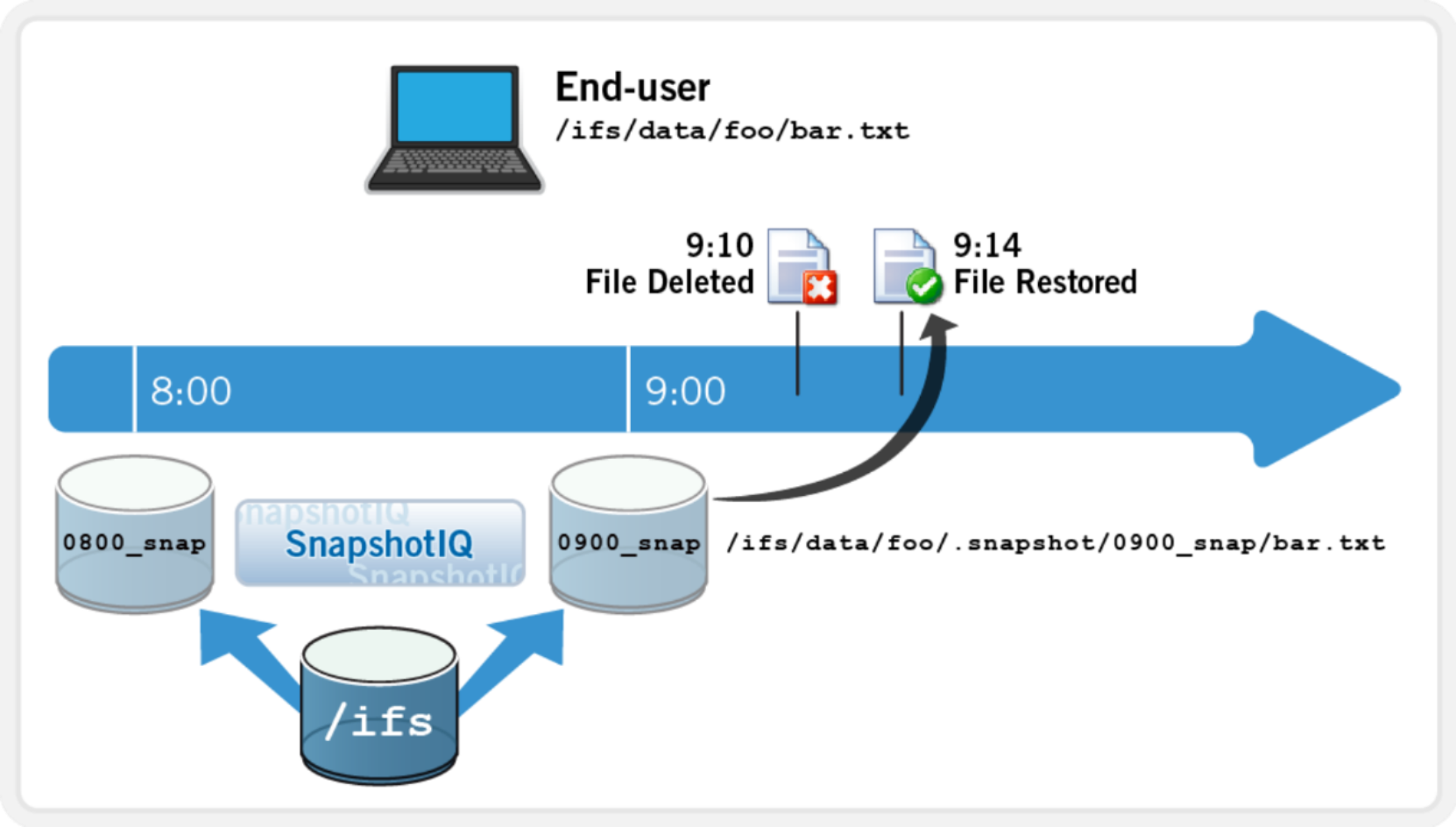
Figure 14. User-driven file recovery with SnapshotIQ
OneFS Snapshots are highly scalable and typically take less than one second to create. They create little performance overhead, regardless of the level of activity of the file system, the size of the file system, or the size of the directory being copied. Also, only the changed blocks of a file are stored when updating the snapshots, thereby ensuring highly efficient snapshot storage utilization. User access to the available snapshots is through a /.snapshot hidden directory under each file system directory.
In EDA environments, snapshots can be configured as per following sample:
- Project data: Multiple snapshots a day with retention up to 1 months
- Home directories: Multiple snapshots a day with retention up to 3 months
- Scratch data: No snapshots
- EDA tools, binaries, libraries: Daily with retention up to 1 month
- Code repositories: Daily or multiple snapshots a day with retention up to 1 months
Writable snapshots
Introduced in OneFS 9.3, writable snapshots enable the creation and management of a space-efficient and time-efficient, modifiable copy of a regular OneFS snapshot. As such, they present a writable copy of a source snapshot, accessible at a directory path within the /ifs namespace. The snapshot can be accessed and edited through the use of any of the cluster’s file and object protocols, including NFS, SMB, and S3.
The writable snapshot architecture provides an overlay to a read-only source snapshot. This architecture allows a cluster administrator to create a lightweight copy of a production dataset using a simple CLI command, and present and use it as a separate writable namespace.
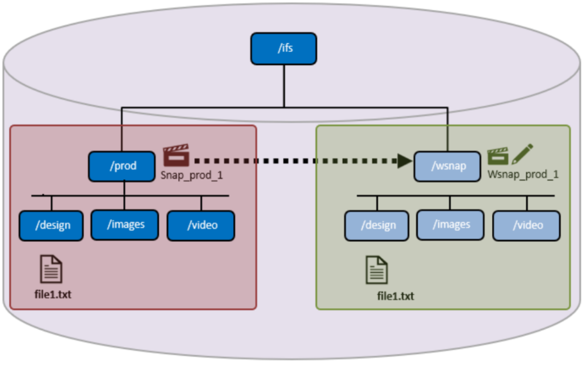
Figure 15. Writable snapshots
A writable snapshot contains the same subdirectory and file structure as the original prod directory, but without the added data capacity footprint.
OneFS 9.3 introduced a new protection group data structure, PG_WSNAP, which provides an overlay that allows unmodified file data to be read directly from the source snapshot while storing only the changes in the writable snapshot tree. When files within a newly created writable snapshot are first accessed, data is read from the source snapshot, populating the files’ metadata, in a process known as copy-on-read, or CoR. Unmodified data is read from the source snapshot and any changes are stored in the writable snapshot’s namespace data structure (PG_WSNAP).
Since a new writable snapshot is not copy-on-read up front, its creation is extremely rapid. As files are later accessed, they are enumerated and begin to consume metadata space.
SnapshotIQ
SnapshotIQ can create unlimited snapshots on a cluster. This provides a substantial benefit over most other snapshot implementations because the snapshot intervals can be far more granular and so offer improved RPOs.
SnapshotIQ has several fundamental differences as compared to most snapshot implementations. The most significant of these are, first, that OneFS snapshots are per directory based. This is in contrast to the traditional approach, where snapshots are taken at a file system or volume boundary. Second, since OneFS manages and protects data at the file-level, there is no inherent, block-level indirection layer for snapshots to use. Instead, OneFS takes copies of files, or pieces of files (logical blocks and inodes) in a logical snapshot process.
SyncIQ
While snapshots provide an ideal solution for infrequent or smaller-scale data loss occurrences, when it comes to catastrophic failures or natural disasters, a second, geographically separate copy of a dataset is clearly beneficial. Here, a solution is required that is significantly faster and less error-prone than a recovery from tape, yet still protects the data from localized failure.
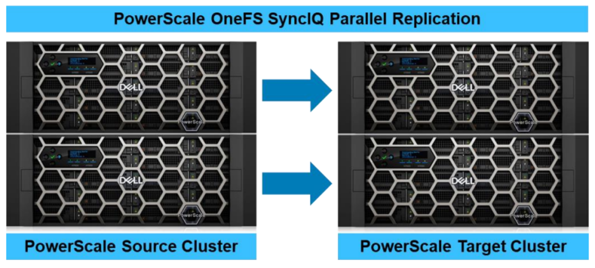
Figure 16. SyncIQ parallel replication across a source and target cluster.
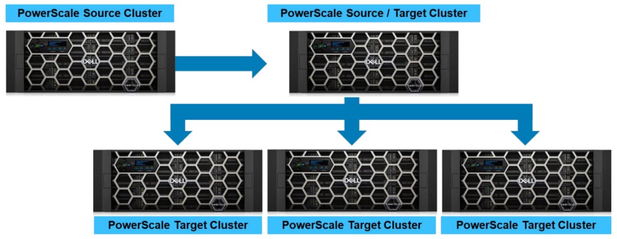
Figure 17. SyncIQ cascaded and one-to-many data replication.
OneFS SyncIQ software delivers high-performance, asynchronous replication of unstructured data to address a broad range of recovery point objectives (RPO) and recovery time objectives (RTO). This enables customers to make an optimal tradeoff between infrastructure cost and potential for data loss if a disaster occurs. SyncIQ does not impose a hard limit on the size of a replicated file system so will scale linearly with an organization’s data growth up into the multiple petabyte ranges.
SyncIQ is easily optimized for either LAN or WAN connectivity and includes policy level bandwidth control and reservation. This allows replication over both short and long distances, while meeting consistent SLAs and providing protection from both site-specific and regional disasters. Also, SyncIQ uses a highly parallel, policy-based replication architecture designed to leverage the performance and efficiency of clustered storage. As such, aggregate throughput scales with capacity and allows a consistent RPO over expanding datasets.
SyncIQ supports up to one thousand defined policies, of which up to fifty may run concurrently. SyncIQ policies also have a priority setting to allow favored policies to preempt others. In addition to chronological scheduling, replication policies can also be configured to start whenever the source is modified (change based replication). If preferred, a delay period can be added to defer the start of a change-based policy.
In EDA environments, SyncIQ can be leveraged to protect data in several different ways starting from replicating EDA Tools and binaries to design project data across different geographical locations for collaborative design challenges. Many customers use SyncIQ to replace physical tape-based backup environments by protecting data to another PowerScale cluster.
SyncIQ encryption
SyncIQ encryption, which is available in OneFS 8.2 and later, ensures that the security of replicated data in-flight. X.509 Transport Layer Security (TLS) certificates used by the nodes in the replicating clusters are managed through the SyncIQ certificate store. SyncIQ encryption can be configured either per-policy or globally.
- For EDA, there’s no specific recommendation for using this feature. Encryption of data is generally a business requirement.
- Encryption adds minimal overhead to the transmission, but it may impact a production workflow depending on the network bandwidth, cluster resources, workflow, and policy configuration. Only after successfully testing encryption in a lab environment and collecting satisfactory measurements, may the production cluster be considered for implementing SyncIQ encryption.
- Both the source and target cluster must be upgraded and committed to OneFS 8.2, prior to enabling SyncIQ encryption.
NDMP backup
At the trailing end of the protection continuum lies traditional backup and restore—whether to tape or disk. With high RPO and RTOs, this is the bastion of any data protection strategy and usually forms the crux of a ‘data insurance policy’
OneFS facilitates performant backup and restore functionality through its support of the ubiquitous Network Data Management Protocol (NDMP). NDMP is an open-standard protocol that provides interoperability with leading data-backup products and OneFS supports both NDMP versions 3 and 4. OneFS also supports both direct NDMP (referred to as 2-way NDMP), and remote NDMP (referred to as 3-way NDMP) topologies.
Direct NDMP model (2-way)
This is the most efficient model and results in the fastest transfer rates. Here, the data management application (DMA) uses NDMP over the Ethernet front-end network to communicate with the cluster. On instruction, the cluster, which is also the NDMP tape server, begins backing up data to one or more tape devices which are attached to it by Fibre Channel.
The DMA, a separate server, controls the tape library’s media management. File History—the information about files and directories—is transferred from the cluster by NDMP to the DMA, where it is maintained in a catalog.
Direct NDMP is the fastest and most efficient model for backups with OneFS. Direct NDMP requires either a B100 backup accelerator (or a pool of Gen6 nodes with Fibre Channel connectors) to be present within a cluster.
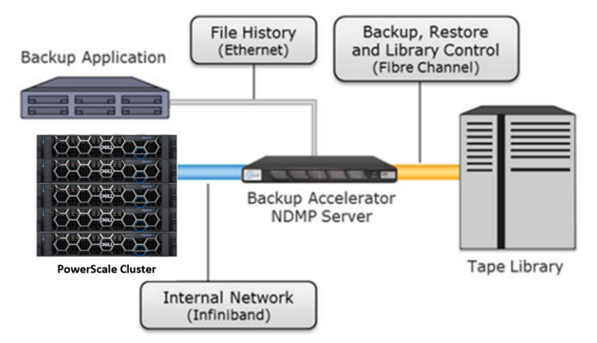
Figure 18. Recommended 2-way NDMP over Fibre Channel
Remote NDMP model (3-way)
In the remote NDMP scenario, there are no Fibre Channel connectors present in the cluster. Instead, the DMA uses NDMP over the LAN to instruct the cluster to start backing up data to the tape server—either connected by Ethernet or directly attached to the DMA host. In this model, the DMA also acts as the Backup/Media Server.
During the backup, file history is transferred from the cluster over NDMP over the LAN to the backup server, where it is maintained in a catalog. In some cases, the backup application and the tape server software both reside on the same physical machine.
OneFS remote NDMP backup also includes intelligent IP selection functionality. This enables backup applications such as Avamar and Commvault to select the most desirable interfaces and preferred network for NDMP traffic.
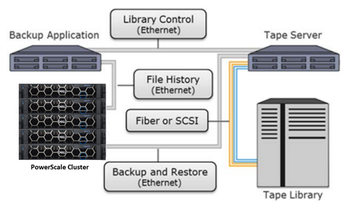
Figure 19. Remove NDMP (3-way) scenario
Archives in EDA environments
In EDA environments, during chip design, the business-critical data related to that design is stored in various project partitions. One design project could be spread out over many partitions ranging from a 100 GBs to 100TB or more. These partitions that constitute a “whole” design may contain a mixture of lot of small files and some large files. In some cases, a design environment has a best practice of storing all necessary design tools along with the project data, and in other cases, tools are maintained separately and centrally. The point is, a full design spans one or more partitions, is large, and contains many billions of files.
While OneFS single namespace significantly reduces the need for many smaller partitions, some partitioning is necessary based on design methodologies adopted by each company. Overall, due to the wholesome nature of hosting designs across partitions, it makes sense to archive the design work by saving all the partitions as-is, so that few years down the road if a design needs a re-spin, the data layout (including any soft/hard links) is intact in archives, with the directory hierarchies preserved just the way it was originally. This provides most flexibility to the designers and shortest time to resume work on the design once it is restored. In contrast, when archive policies are designed around access time of files, it may end up archiving parts of a project, leaving behind some files in the original production partition.
Linux is prevalent in semiconductor environments, and the usage of autofs (automatic mounting of network filesystems) functionality integrated with the NFS export rules and authentication providers seems to be normal. With thousands of partitions for projects, scratch spaces, tools, home directories, it can be daunting for the IT admin to maintain a clean set of automounter maps.
With the above information around design archives and associated Linux environment challenges, following best practices for semiconductor archives can be considered.
- Provision a separate cluster for archives using capacity nodes such as the A3000/A300 or faster H7000/700. Note, a cluster that is designed to host SyncIQ backups could also be used for archives.
- If archives are to be protected, SyncIQ can be used to protect it on another cluster or CloudPools can be used to archives to public cloud.
- Alternatively, the Dell ECS object storage platform or ObjectScale storage can also be an archive target, providing geo replication and global namespace capabilities among other benefits.
- The goal is to provide online archive capabilities, which is an incentive to the designer to archive more, knowing the data is available instantly to read.
- Create a separate map such as /archives for all projects. For e.g., it can be available to designers as /archives/projectabc for a project, /archives/projectabc_scratch for the associated scratch partition, and /archives/projectabc_tools for specific tools that could be archived.
- Have a separate data lifecycle policy and process for defunct home directories, and retired tools and libraries.
The data under /archive should be available as read-only, while the top-level archive directory on the archive cluster is available as read-write export for administrative hosts.
Data classification is key to successful archive policies in the company. Giving the designers ability to see the aging of their data, being able to manage their own data classification, tagging their partitions, and letting them archive it on a routine basis are all good measures for an effective data life cycle management.
General EDA Engineering IT architecture
This section covers general EDA engineering IT architecture model as block design example to show core component of EDA engineering IT.
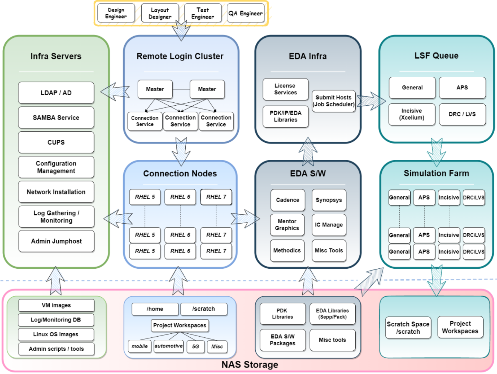
Figure 20. General EDA engineering IT architecture
Common Infra servers
Common infrastructure servers include authentication (LDAP/AD, NIS...), Samba service, CUPS printing service, Configuration management service (CFEngine, Ansible…), Linux network installation service, Log gathering and monitoring services (InsightIQ, Grafana…), and SSH jumphost for management.
Remote login cluster
Remote login cluster to allow chip designer to access Linux/Unix server resources, project data, EDA software and job scheduler for daily IC design activity from windows-based platform. Remote login software support suspends and resumes of current working environments, access control for chip designer, secure encryption protocol, session management and configuration database. Usually consist of at least 2 servers for redundancy.
Connection nodes
Pool of server cluster consist of various version of Linux platform depending on project type and EDA software requirements. Most of EDA design software are running on this cluster and controlled by configuration management service to maintain all servers have same configuration and policy.
EDA engineering IT team have multiple policy based on designer’s job role, project priority and EDA software requirements to allocate reasonable amount of cluster resources to each chip designer. Sometime network latency is important for remote working designer and some EDA software require very high memory over 512G.
EDA infrastructure
EDA software and libraries, license service, job scheduler and simulation farm. Chip designers submit simulation jobs to job scheduler. Job schedulers monitor each server’s resources in the simulation farm and allocate required resource to run simulation jobs.
Depending on the type of simulation and EDA software, digital simulation tends to favor server with high clock speed, large L3 cache and high memory for single-threaded performance to minimize license checkout time, analog simulation tends to favor server with high core counts for multi-core performance to minimize job run time. Some physical design software requires very high memory such as place and route. Physical design verification job tends to run very longer time.
So, simulation farm has different servers dedicated to specific software and job type. EDA engineering IT team need schedule each workload carefully to maximize simulation farm resources and minimize license checkout time.
Scalable NAS storage
New advancements of 7nm, 5nm, and 3nm process nodes have introduced complex design challenges for chipmakers, specifically the growing needs for scalable storage performance. Data is the new capital and asset for chipmaker, and it is growing exponentially. Combined with vast amounts of data generated from much denser chip designs, and growing compute farms that are now using GPUs, the scale-out NAS storage is a key piece how unstructured storage affects their ability to deliver value and improve time to market metrics.
EDA Engineering Reference Design example
This section covers industry reference design approaches. Customers in semiconductor industry deploy PowerScale scale-out storage in a variety of ways that encompass meeting a spectrum of business requirements. As the semiconductor design and manufacturing continues to leverage newer technologies like Generative AI, Machine Learning (ML), Analytics and Large Language Models (LLM), customers are rapidly enhancing their approach to shared storage deployments.
Below EDA engineering infrastructure example may shed some light on what we may call EDA reference design approaches customers are taking to solve their challenges.
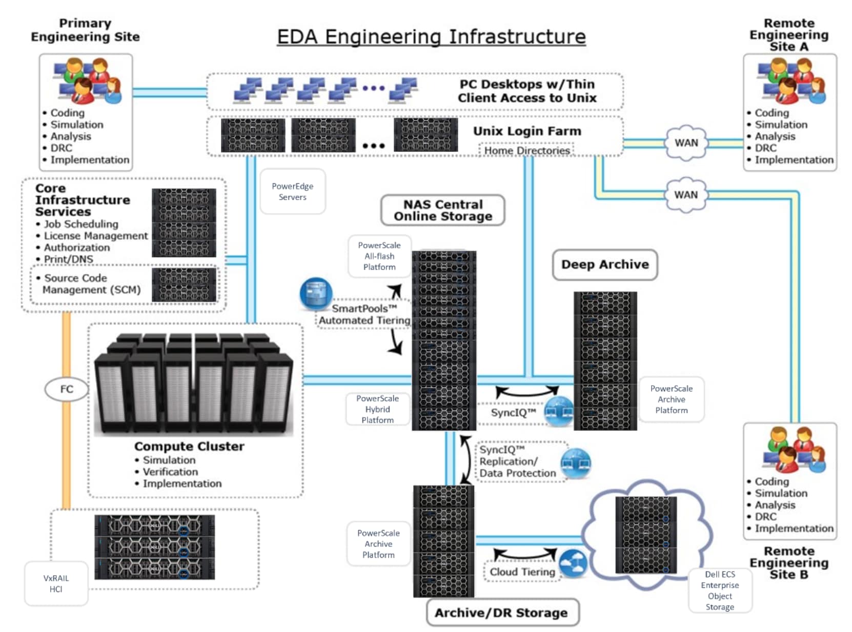
Figure 21. EDA Engineering Infrastructure model
References
Dell Technologies documentation
The following Dell Technologies documentation provides other information related to this document. Access to these documents depends on your login credentials. If you do not have access to a document, contact your Dell Technologies representative.