Windows Server 2025 Deployment and Operations Guide with Switchless Networking
This deployment and operations guide focuses on using PowerShell to deploy a HCI solution with switchless storage design, which is built on validated and certified AX nodes from Dell Technologies with a Windows Server 2025 operating system.
Note: A NOTE indicates important information that helps you make better use of your product.
CAUTION: A CAUTION indicates either potential damage to hardware or loss of data and tells you how to avoid the problem.
Warning: A WARNING indicates a potential for property damage, personal injury, or death.
About copying commands from this guide
About copying commands from this guide
CAUTION: Many PDF editors and viewers add a line break to the end of each line of text in a PDF. As a result, when you copy commands that wrap across multiple lines in a PDF, the copied command is in the wrong format. It contains erroneous line breaks that might cause the script to fail.
To address this known limitation, do one of the following:
Paste the copied commands into a text editor and remove the line breaks.
Use the HTML version of this document when you are copying commands.
Revision history
Revision history
The revision history of the document is listed in the following table.
Table 1. Revision history
Date
Document revision
Description of changes
April 2026
2
Removed table and revised information and references in "Antivirus exclusions" topic
Renamed "About using this guide" to "About copying commands from this guide"
Added information about setting the "IEEE Priority Tag"
Under "Non-converted network configuration" changed figure 5 to corrected diagram
Updated steps for "Configure host networking" topic
Added caution about character limit to "change the hostname" topic
Under "Configure Network ATC" section, updated steps in "Converged intent" and "Non-converged intent" topics
Replaced QoS flow priorities table in "Converged intent" and "Non-converged intent" topics
Updated cmdlet in "Enabling Storage Spaces Direct" topic
Added "Configuring host management network as a lower-priority network for live migration" topic
Restored "Best practices and recommendations" section and topics
Added "Configure cluster witness topic"
Under "Day 2 operations" section, updated "Preparing for maintenance mode" and "Placing a node into maintenance mode" topics
Added "GPU Integration" chapter
Updated overview of "Dell OpenManage Integration with Windows Admin Center" section
Minor updates throughout document
October 2025
1
Updates related to an internal defect
Minor updates throughout document
June 2025
0
Initial publication
Deployment Introduction
Deployment Introduction
Document overview
This end-to-end deployment guide offers an overview of Dell AX System for Microsoft Windows Server. It provides guidance on integrating solution components and detailed instructions for preparing and deploying the solution infrastructure. Dell AX System for Microsoft Windows Server includes the Dell AX System for Microsoft Windows Server 2025 Data Center edition.
Audience and scope
The audience for this document includes systems engineers, field consultants, partner engineering team members, and customers with knowledge about deploying hyperconverged infrastructures (HCIs) with the Windows Server operating system, Hyper-V, and Storage Spaces Direct. Customers who do not have Volume License agreements with Microsoft can order AX nodes from Dell Technologies with a factory-installed operating system and OEM license or as a bare-metal installation. The HCI cluster can be deployed in the following ways:
Dell Technologies Services-led—Certified deployment engineers ensure accuracy, speed, and reduced risk and downtime.
Customer led: Customers who have the qualified level of technical expertise follow the instructions in this guide.
Note: Instructions in this deployment guide are applicable only to the Windows Server 2025 GA build with the latest operating system updates. AX nodes from Dell Technologies do not support the Windows Server Semi-Annual Channel release. Dell Technologies recommends that you update the host operating system with the latest cumulative updates from Microsoft before starting the cluster creation and configuration tasks
Assumptions
This guide assumes that deployment personnel understand the following technologies and tasks:
AX nodes from Dell Technologies
Deploying and configuring BIOS and integrated Dell Remote Access Controller (iDRAC) settings
Deploying and configuring Windows Server operating system and Hyper-V infrastructure
Solution Introduction
Solution Introduction
Solution overview
Dell AX Solutions for Microsoft includes various configurations of AX nodes. These AX nodes power the primary compute cluster that is deployed as an HCI solution. The HCI solution uses a flexible solution architecture rather than a fixed component design.
The solutions are available in both hybrid and all-flash configurations. For more information about available configurations, see the Dell AX System for Microsoft Windows Server specification sheet.
Deployment models
Dell AX Solutions for Microsoft offer the following types of cluster infrastructure deployments:
Scalable infrastructure
Switchless storage networking
Dell AX Solutions for Microsoft does not include:
Management infrastructure components such as a cluster for hosting management virtual machines such as Windows Admin Center (WAC)
Services such as Microsoft Active Directory and Domain Name System (DNS)
The instructions in this guide do not include deployment of any of these services and components, and they assume that at least an Active Directory domain controller is available in the existing management infrastructure. In a remote office scenario, Dell Technologies recommends that you deploy either an Active Directory replica or read-only domain controller (RODC) at the remote office. If you are using an RODC at the remote site, connectivity to the central management infrastructure with a writeable domain controller is mandatory during deployment of the cluster.
Scalable infrastructure
The scalable offering within Dell AX Solutions for Microsoft encompasses various AX node configurations. In this Windows Server 2025 solution, as many as 16 AX nodes power the primary compute cluster.
The following figure shows one of the flexible solution architectures. It includes the Windows Server instance, redundant top-of-rack (ToR) switches, a separate out-of-band (OOB) network, and an existing management infrastructure in the data center.
Figure 1. Scalable solution architecture
Scalable networking
Dell AX System for Microsoft Windows Server hyperconverged scalable architectures support from two to sixteen nodes in a cluster. The scalable architectures support fully converged, non-converged, and disaggregated network topologies.
Adapter requirements
Azure Local requires using the same adapter card vendor and model for the machines in an instance that support instance operations. The ports that are used by the same Network ATC intent must use the same vendor, model, and speed. Configurations that also require NIC-level high availability must use the same vendor, model, and speed that is installed in the PCIe riser slots instead of the OCP slot.
CAUTION: If you use optics or cables from one vendor with an adapter card from another vendor, Dell cannot guarantee that your configuration will work as expected. Before you mix vendor equipment in an Azure Local instance, consult the Dell Technologies cable and optics in the Support Matrix.
Fully converged network configuration
In the fully converged network topology, management, compute, and storage (SMB) ports from the server are connected to the same highly available network fabric. In the host operating system, the NIC ports are used for both storage and management/compute traffic. The following figure shows this configuration in the host operating system.
In this host operating system network configuration, a Fully Converged Intent is created with two ports and virtual adapters in the host operating system that is implemented for Storage 1, Storage 2, and Management traffic.
Figure 2. Host operating system network configuration in fully converged topology
The following figure depicts the integration of the fully converged architecture.
Figure 3. Fully converged network topology
The following figure depicts the AX-4510c fully converged network topology with embedded LOM.
Figure 4. AX-4510c/AX-4520c fully converged network topology with embedded LOM
Non-converged network configuration
In the non-converged configuration, Dell Technologies recommends the following:
Storage intent is created for storage traffic using the dedicated PCIe NIC ports
A management and compute intent is created for the OCP card ports
The following figure depicts this configuration:
Figure 5. Storage on physical links in a non-converged topology with two NIC ports
The following figure depicts a non-converged network topology with embedded LOM:
Figure 6. Network integration in a non-converged configuration with two NIC ports
The following figure depicts AX-4520c non-converged network topology with PCIe NICs:
Figure 7. AX4520c non-converged network topology with PCIe NICs
Note: The Embedded LOM in an AX-4520c is always an Intel E823 card. If you choose to use a Mellanox card for your configuration, you can cable the systems accordingly by using two PCIe cards.
Solution deployment
Solution deployment
Deployment prerequisites
Dell Technologies assumes that the management services that are required for the operating system deployment and cluster configuration are in the existing infrastructure where the HCI cluster is being deployed.
The following table describes the management services:
Table 2. Management services
Management service
Purpose
Required/optional
Active Directory
User authentication/authorization
Required
Domain Name System
Name resolution
Required
Windows Admin Center
Monitor/Management tool
Required
DHCP
Hosts get IPs before and after host configuration via Network ATC
Optional
Install Dell OpenManage Integration with Microsoft Windows Admin Center
To seamlessly integrate Dell OpenManage with Microsoft Windows Admin Center (OMIMSWAC), do the following:
Ensure that you have Windows Admin Center installed.
In Windows Admin Center, go to Settings > Extensions.
Under the Available extensions tab, select and install Dell OpenManage Integration.
After installation, you can access the Dell OpenManage Integration extension on the left panel of the cluster manager, under Extensions.
IPv4 network range for management and storage networks
The following IP addresses and VLANs are part of the Network ATC configuration examples.
Table 3. IP addresses and subnet details for management and storage networks
Hostname
Management
Node1
192.168.10.11/24
Node2
192.168.10.12/24
Node3
192.168.10.13/24
Node4
192.168.10.14/24
HCIcluster
192.168.10.100/24
Table 4. VLANs and gateways
Names
VLAN
Gateway
Management
202 (TOR1+ TOR2)
192.168.10.1
Storage 1
711
N/A
Storage 2
712
N/A
Registering a Partner Admin Link (PAL) for Azure related solutions
Partner Admin Link (PAL) is a simple telemetry-based capability that is built into Microsoft Azure. PAL enables Microsoft to track partner involvement in Azure related technical engagements.
Adding a Dell Partner ID to the Service Principal does not provide Dell with additional access to the customer system and does not change any Azure Role-Based Account Controls (RBACs).
Note: Adding a Dell Partner ID to the Service Principal associates Dell to the customer entity, which is persistent. This means that changes in customer system administrators do not break this association.
Dell Technologies employees can add a PAL using the user ID associated with either the subscription or Service Principal that is used for Arc or for Azure Local registrations. During a deployment, the customer creates the Service Principal for their system.
Example: az managementpartner create --partner-id 913990
az managementpartner create --partner-id <Partner ID>
The following figure shows an example of a completed registration in Azure CLI.
Figure 8. Successful addition of Partner ID to customer tenant
Alternatively, you can verify the registration, either using the following CLI command or in the Azure portal. This command displays a similar output to the az managementpartner create command used in the previous step.
az managementpartner show
Note: If there is an error when you add the Dell Partner ID, use the following command to correct the registration:
az managementpartner update --partner-id <Partner ID>
The PAL is now registered.
Add a PAL through the Azure portal using the subscription user ID
You can register the Partner Admin Link (PAL) with the subscription user ID through the Azure portal.
Note: Portal-based registrations tie the PAL association with the customer user entering the information. If the customer user changes roles, the portal-based PAL association also ends.
The portal-based update is not audit-log tracked, while the CLI-based update is tracked.
If possible, Dell Technologies recommends that you use the user ID associated with the Service Principal for PAL registration.
To add a PAL to a customer user account using the subscription user ID, do the following:
From Portal Settings, under Useful links, select Microsoft partner network.
Figure 10. Microsoft partner network link under Portal Settings
Note: If multiple directories are listed, confirm the Azure tenant, and then use the tenant that is associated with Arc registration.
From Link to a partner ID, in Microsoft partner ID, type the Microsoft Partner Network (MPN) identifier that is associated with the country or region of engagement.
Figure 11. Microsoft partner ID field
To activate it, click Link a partner ID.
The PAL is now registered.
Dell Technologies Partner IDs for Partner Admin Link
The following table provides a list of Dell Technologies partner IDs that can be used for Partner Admin Link (PAL) registration with Microsoft.
Note: For partner IDs for any countries that are not listed, contact the Strategic Partnerships and Global Alliances team.
Table 5. Dell Technologies MPN Partner IDs for PAL use
Country
MPN ID
Argentina
1973856
Australia
1576776
Austria
1444496
Belgium
1447258
Brazil
1563635
Canada
742767
Chile
2389235
China
2580218
Colombia
1736279
Czech Republic
1980606
Denmark
1449600
Finland
1993462
France
892181
Germany
1449416
Greece
3679221
Hong Kong Sar
2790298
India
2419713
Indonesia
2834572
Ireland
1447272
Italy
1446223
Japan
578508
Korea
2153293
Malaysia
2731874
Mexico
724848
Netherlands
1446198
New Zealand
1872429
Norway
1446238
Panama
1477223
Poland
3697305
Portugal
1552205
Romania
1735552
Russia
4543982
Singapore
2773797
Slovakia
3812320
South Africa
1970176
Spain
1004323
Sweden
1449417
Switzerland
1449592
Taiwan
5097219
Thailand
2345177
Turkey
3396579
United Arab Emirates
3159758
United Kingdom
1447267
United States
913990
Pre-deployment configuration
Configuring iDRAC and BIOS setting
The AX nodes are factory-configured with optimized system BIOS and iDRAC settings. This factory configuration eliminates the need for you to manually configure the settings to a recommended baseline. The iDRAC in AX nodes can be configured to obtain an IP address from DHCP or can be assigned a static IP address. When the OOB network in the environment does not provide DHCP IP addresses, you must manually set a static IPv4 address on each iDRAC network interface. You can access the physical server console to set the addresses by using KVM or other means.
Configure the top-of-rack (ToR) network switches to enable management and compute. Dell Technologies recommends that you deploy a network topology that supports a dual control plane while sharing a single data plane. Virtual Link Trunking (VLT) is Dell Technologies proprietary technology that provides network resiliency for data I/O.
Configuring switch VLT redundancy with Virtual Router Redundancy Protocol (VRRP) provides a virtual floating IP address that any node can reference as a gateway. If a switch fails, the virtual IP address is transferred to a peer switch.
VRRP is an active/standby, first-hop redundancy protocol (FHRP). When used with VLT peers, VRRP becomes an active/active protocol. The VRRP virtual MAC address is the local destination address in the forwarding information base (FIB) table of both VLT peers. Using this method, the backup VRRP router forwards intercepted frames that have a destination MAC address that matches the VRRP virtual MAC address.
A standard Storage Spaces Direct deployment requires three basic types of networks: OOB management, host management, and storage. The number of network ports (two or four) that are used within the storage configuration determines whether you have two or four fault domains.
Use this procedure to configure the Intel E810 or E823 network adapter for each port. The Intel E810 and E823 network adapters support both iWARP and RoCE v2 RDMA protocols.
During system startup, press F2 to enter system setup and select Device Setting.
Select Intel E810 or E823 network adapter from the list of adapters.
Click Device Level Configuration and ensure that Virtualization Mode is set to None.
Click Back, then on the Main Configuration page, scroll down and select Enabled for NIC + RDMA Mode.
Click Back > Finish > Yes to save the settings.
Click Yes to return to the Device Settings page.
Select the second port of the Intel adapter and repeat the preceding steps.
Click Finish to return to the System Setup page.
Click Finish to reboot the system.
Configure Broadcom 57504 NICs
The Broadcom 57504 network adapter supports only ROCE v2 RDMA protocol and can be configured on both converged and hyperconverged deployments. Both OCP and PCIe cards are available.
Ensure that the network card or port is enabled for RDMA traffic.
To configure the Broadcom 57504 network adapter for each port, do the following:
During system startup, to enter System Setup, press F2, and then select Device Settings.
From the list of adapters, select Broadcom network adapter.
Select Device Level Configuration, and from the menu choose the DCBX Mode option, and then choose Enabled (IEEE Only). Ensure that Virtualization Mode is set to None.
Click Back.
In the Main Configuration window, set NIC + RDMA Mode to Enabled. To save the settings, click Finish.
To return to the Device Settings window, click Yes.
Select the next port of the Broadcom adapter and repeat the previous steps.
To return to the System Setup window, click Finish.
To reboot the system, click Finish.
Operating system deployment
Dell AX nodes support manual or factory-installed deployment of Windows Server 2025 using iDRAC and Lifecycle Controller.
Manual operating system deployment
Dell Lifecycle Controller and iDRAC provide operating system deployment options. Options include manual installation or unattended installation by using virtual media and the operating system deployment feature in Lifecycle Controller for Windows Server 2025 operating system.
A step-by-step procedure for deploying the operating system is not within the scope of this guide.
This guide assumes that:
Windows Server 2025 operating system installation on the physical server is complete.
If the cluster nodes are shipped from Dell Technologies with a preinstalled operating system, complete the out-of-box experience (OOBE):
Select language and locale settings.
Accept the Microsoft and OEM EULAs.
Set up a password for the local administrator account.
Update the operating system partition size, and shrink it as needed.
The OEM operating system is preactivated, and the Hyper-V role is predeployed for Windows Server 2025. After completing the OOBE steps, perform the steps to complete the cluster deployment and Storage Spaces Direct configuration.
The Windows Server 2025 operating system factory image has multilingual support for these languages: English, German, French, Spanish, Korean, Japanese, Polish, and Italian. To change language:
Run the following PowerShell commands. <LANGUAGE> can be en-US, fr-FR, ja-JP, ko-KR, de-DE, pl-PL, it-IT, or es-ES.
Set-WinUserLanguageList <LANGUAGE>
Set-WinSystemLocale -SystemLocale <LANGUAGE>
Reboot after running the commands.
Note: For all the languages except Polish, the main screen changes to the appropriate font. For Polish, the English font is used.
Note: Do not run your virtual machine with the VHD file residing on the BOSS device (for example, C:\). It should always be on C:\ClusterStorage\<CSV>
Host configuration
Set up host networking through iDRAC and PowerShell by assigning IPs, setting VLANs, enabling remote access, and configuring time sync and WinRM for cluster readiness.
Configure host networking
Use the iDRAC virtual console to access the host console of each system and configure the network settings.
To host networking configuration steps, run the following commands in PowerShell:
Identify the network interface controllers to be used for the management/compute traffic and assign management IP address to the first port:
New-NetIPAddress -InterfaceAlias "Integrated NIC 1 Port 1-1" -IPAddress 192.168.10.11 -DefaultGateway 192.168.10.1 -PrefixLength 24 -AddressFamily IPv4 –Verbose
Note: This step is not needed if you have DHCP in your environment. Ensure that the hosts are assigned IPs in the correct VLAN.
Set VLAN ID for management adapters:
Get-NetAdapter -Name "Integrated NIC 1 Port 1-1" | Set-NetAdapter -VlanID 202 -Confirm: $false
Note: This step is not needed if the VLAN is untagged.
Set a DNS IP address:
Set-DnsClientServerAddress -InterfaceAlias "Integrated NIC 1 Port 1-1" -ServerAddresses 192.168.11.50
If you do not use DHCP to configure the management adapter, to disable DHCP on all network ports other the OS-to-iDRAC Pass-through adapter, run the following command:
If you use DHCP to configure the management adapter, to disable DHCP on all network ports other than the first port of management adapter and the OS-to-iDRAC Pass-through adapter, run the following command:
Note: Update your management adapter name accordingly, as shown in the following example:
Note: Some Windows features require a system restart during installation. To streamline the process, all required restarts are combined into a single reboot.
Run the following PowerShell commands to confirm the successful installation of features:
By default, the operating system deployment assigns a random name as the host system name. For easier identification and uniform configuration, Dell Technologies recommends that you change the hostname to something that is relevant and identifiable.
CAUTION: The computer and cluster names cannot be more than 15 characters. If the name exceeds the character limit, the deployment will fail when the system tries to encrypt the volume.
Change the hostname by using the Rename-Computer cmdlet:
Rename-Computer -NewName Node01 -Restart
Note: This command induces an automatic restart at the end of rename operation.
Add a node to domain
Before you can create a cluster, the cluster nodes must be a part of an Active Directory domain.
You can perform the domain join task by running the Add-Computer cmdlet on each host that will be a part of the cluster.
Note: Optionally, you can add all newly created computer objects from the cluster deployment to a different Organizational Unit (OU) in Active Directory Domain Services. In this case, you can use the -OUPath parameter along with the Add-Computer cmdlet.
Note: This command induces an automatic restart at the end of the domain join operation.
Update firmware and drivers
Dell AX System for Windows Server is validated and certified with certain firmware and driver versions that are related to the solution infrastructure components.
Use the validated firmware and software, as specified in the Support Matrix, to ensure that the solution infrastructure remains supported and delivers optimal performance.
You can verify compliance and update the servers (nodes) with a Windows Server 2025 online or offline catalog by using Dell OpenManage Integration with Windows Admin Center (OMIMSWAC).
In Windows Admin Center, in the left pane, click Add.
Select Add manually. Under Servers:
Click Add.
Enter the server name.
To save the name, click Add.
Under All connections, select the server, and then click Manage as.
Select use another account for this connection and then provide the credentials in the domain\username or hostname\username format.
Review the Dell Software License Agreement and Customer Notice and select the checkbox to accept the terms of the license agreement.
From the list menu, select View: Compliance, and then select Hardware Updates.
Click Check compliance and select either the online catalog or offline catalog.
Click Fix Compliance and select update to update the node.
Alternatively, use Dell System Update (DSU) to update standalone servers before cluster deployment. For more information, see DSU.
Creating a cluster
Creating a cluster
To set up a Windows Server 2025 networking environment with Network ATC, first create a cluster, then configure network intents using Network ATC. Enabling S2D is the last step.
Run the following PowerShell command to exclude remote NDIS NIC (operating system to iDRAC pass-through) from cluster networks.
The Test-Cluster cmdlet generates an HTML report of all performed validations and includes a summary of the validations. Review this report, resolve all warnings and errors before creating a cluster.
Run the Get-PhysicalDisk PowerShell command on all cluster nodes.
Verify the output to ensure that all disks are in the healthy state and that the nodes have an equal number of disks. Verify that the nodes have homogenous hardware configuration.
Run the following PowerShell command to create a cluster from any of the cluster nodes.
In this command, the StaticAddress parameter is used to specify an IP address for the cluster in the same IP subnet as the host management network. The NoStorage switch parameter specifies that the cluster is created without any shared storage.
The New-Cluster cmdlet generates an HTML report of all performed configurations and includes a summary of the configurations. Review the report before enabling Storage Spaces Direct.
Configure Network ATC
Network ATC is a feature in Windows Server 2025 that streamlines and enhances the deployment and management of host networking within clusters. It uses an intent-based approach, allowing you to define intents (such as management, compute, or storage) for network adapters. This method ensures that all network adapters assigned to the same intent configuration are symmetric across each cluster node.
Converged intent
In the fully converged network topology, all storage ports from the server are connected to the same network fabric. In the host operating system, the NIC ports are used for both storage and management/compute traffic.
In this example, SLOT 1 Port 1 and SLOT 1 Port 2 are being used to create a converged Intent. Verify that SLOT 1 Port 1 and SLOT 1 Port 2 are up across all the nodes.
Modify the NIC variables to match the deployment requirements.
$mgmt_compute_stor_nics = @('SLOT 1 Port 1','SLOT 1 Port 2')
$storage_vlans =@(711,712)
$Mgmt_Vlan=202
Create an override object for the DCB Quality of Service (QoS) configuration.
Note: The cluster bandwidth is defined as 2 percent using an override to ensure the configuration on the host operating system and the switch is consistent.
The following table shows the QoS flow priorities for each network type:
Table 6. QoS priorities for network intents
Traffic class
Purpose
QoS flow
ETS bandwidth allocation
3
RDMA (SMB Direct)
Enabled
50 percent
7
Cluster network
Disabled
10 GbE equals 2 percent
Greater than 25 GbE equals 1 percent
0-2, 4-6
0 - Best-effort traffic
Disabled
Remaining percentage distributed across the traffic classes
Create a jumbo packet override for converged topology.
Note: If you have Intel E810 or E823 cards, you can choose iWARP or RoCE protocols for SMB Direct traffic according to your data-center standards. Dell Engineering does not have a recommendation on using one over the other.
Set storage overrides if you do not want Network ATC to assign SMB IPs automatically.
# Assign IP addresses for each storage network which we identified in the previous step.
$stor_prefix='24'
$stor1_ip_address = '192.168.11.11'
$stor2_ip_address = '192.168.12.11'
The Test-Cluster cmdlet generates an HTML report of all performed validations and includes a summary of the validations. Review this report, resolve all warnings and errors.
Non-converged intent
In a non-converged network topology, storage (SMB) traffic passes using dedicated NICs and is separated from Management and Compute traffic. This topology is ideal for environments where you expect heavy write IOs. Management and Storage traffic pass using a different pair of NIC ports. In the host operating system, a pair of RDMA capable NICs that is used for storage traffic while Management/Compute can use any supported network card.
In this example, Integrated NIC 1 Port 1-1, Integrated NIC 1 Port 2-1 are being used for the management and compute intent and SLOT 6 Port 1 and SLOT 6 Port 2 are used for the storage intent.
Verify that Integrated NIC 1 Port 1-1, Integrated NIC 1 Port 2-1, SLOT 6 Port 1, and SLOT 6 Port 2 are up across all the nodes.
Note: Mellanox OCP cards can be used for management or storage traffic.
Modify NIC variables to match the deployment requirements.
$mgmt_compute_nics = @('Integrated NIC 1 Port 1-1','Integrated NIC 1 Port 2-1')
$storage_nics = @('SLOT 6 Port 1','SLOT 6 Port 2')
$storage_vlans =@(711,712)
$Mgmt_Vlan=202
Create an override object for the DCB Quality of Service (QoS) configuration.
Note: Before changing net intents, you must set the DCBX Willing mode on every cluster node.
Choose the RDMA protocol to be used for deployment.
#Intel E810 network adaptor support iWARP and RoCEV2 while Mellanox/Nvidia support only RoCEV2.
#iWARP = 1 RoCEv2 = 4
$StorAdapterPropertyOverrides.NetworkDirectTechnology = 4
Set storage overrides if you do not want Network ATC to assign SMB IPs automatically.
The Test-Cluster cmdlet generates an HTML report of all performed validations and includes a summary of the validations. Review this report, resolve all warnings and errors.
Verify DCB settings
To verify the Data Center Bridging (DCB) settings, you can use these PowerShell commands:
Get-NetQosPolicy
Get-NetQosTrafficClass
Get-NetQosFlowControl
Get-SmbClientNetworkInterface
Enabling Storage Spaces Direct
After you create the cluster, to configure Storage Spaces Direct on the cluster, you run the Enable-ClusterStorageSpacesDirect cmdlet.
Note: Do not run the cmdlet in a remote session; instead, use the local console session.
To configure Storage Spaces Direct on the cluster, run the following cmdlet:
The Enable-ClusterStorageSpacesDirect cmdlet generates an HTML report of all configurations and includes a validation summary.
Review this report, which is typically stored in the local temporary folder on the node where the cmdlet was run. The verbose output of the command shows the path to the cluster report. At the end of the operation, the cmdlet discovers and claims all the available disks into an auto-created storage pool.
To verify that Storage Spaces Direct is enabled, run any of the following commands:
Get-ClusterStorageSpacesDirect
Get-StoragePool
Get-ClusterPerformanceHistory
Configure host management network as a lower-priority network for live migration
After you create the cluster, live migration is configured by default to use all available networks.
During normal operations, using the host management network for live migration traffic might impede the overall cluster role functionality and availability. Rather than disabling live migration traffic on the host management network, you can configure the host management network as a lower-priority network in the live migration network order:
To configure the host management network, run the following commands on any one node of the cluster:
A cluster witness must be configured for a two-node cluster. Microsoft recommends configuring a cluster witness for a cluster. Cluster witness configuration helps maintain a cluster or storage quorum when a node or network communication fails and nodes continue to operate but can no longer communicate with one another.
A cluster witness can be either a file share or a cloud-based witness.
Note: If you choose to configure a file share witness, ensure that it is outside the two-node cluster.
Open Windows Explorer and create a folder on a shared disk that you want to share out for users.
Assign the appropriate NTFS file level permissions on the folder. Ensure that the account used to start the Cluster Service has at least READ rights to the folder.
To set a file share witness, run the following command :
Note: You must order AX nodes that are preconfigured for GPU integration, or converted for GPU use, including the required components.
Guidelines for installing GPU hardware
For deployed Azure Local instance, before performing any GPU hardware changes, place the target machine into maintenance mode (pause and drain).
Use Dell Support to follow the platform-specific GPU installation procedure for your server model.
For model-specific GPU slot or riser matrices and riser configuration options, see the applicable Dell installation and service manual sections for your platform, including:
You can use Discrete Device Assignment (DDA) on supported GPUs so that the Azure Stack HCI and Windows Server 2025 and later operating system servers contain GPU-enabled clustered VMs.
The package contains the required driver for the virtual machine to use a GPU that is assigned through Discrete Device Assignment (DDA). With DDA (full device passthrough), you install the NVIDIA driver that enables GPU functionality in the guest virtual machine. In the DDA workflow, the NVIDIA guest driver is not required on the host. If no vendor display driver is installed, the host can show the GPU as a 3D Video Controller.
You can do DDA with either Windows Admin Center (WAC) or PowerShell. Dell Technologies recommends using WAC to reduce user error and to conform to best practices.
Note: Before configuring DDA, to make the GPU available for assignment to the virtual machine, you must disable and dismount the GPU from the host-management operating system.
If you are using Windows Admin Center (WAC) to configure GPU assignment, WAC automatically performs the required disable and dismount operations as part of the workflow, so you do not have to complete this step manually. This automation is one of the reasons that Dell Technologies recommends that you use WAC for GPU-related actions. For more information about configuring and performing a DDA, see Use GPUs with Discrete Device Assignment in clustered VMs.
When DDA is complete and the GPU is assigned to the virtual machine, install the NVIDIA guest driver inside the guest virtual machine so that the virtual machine can use the GPU.
Note: For Windows guests, the driver is in the Guest_Drivers folder of the archive and has an .exe extension.
When the guest driver is installed, your virtual machine is ready to use the DDA GPU. For NVIDIA software licensing requirements, modes, and license-server configuration guidance, see the NVIDIA Virtual GPU Software Client Licensing User Guide.
GPU partitioning
On the Azure Stack HCI or Windows Server 2025 or later operating-system servers, you can use GPU partitioning (GPU-P) for different workloads, such as artificial intelligence. To avoid mistakes and for a streamlined visual experience, Dell Technologies recommends that you use Windows Admin Center (WAC) for GPU-P.
Dell Technologies servers do not come with a GPU-P driver. The GPU-P driver requires separate licensing from NVIDIA. For more information about licensing options and the benefits of GPU-P, see: NVIDIA Virtual GPUs.
Note: For GPU-P to work, you must have both a host driver and a GPU-P enabled guest (VM) driver and the correct activated license.
Download and install host and guest drivers
For GPU partitioning (GPU-P) to work, you must have both a host driver and a GPU-P enabled guest (VM) driver and the correct activated license.
To download and install host and guest drivers, do the following:
When you create a cluster and enable Storage Spaces Direct, the system only sets up a storage pool without provisioning any virtual disks. To create new virtual disks as cluster shared volumes for the cluster, use the New-Volume cmdlet.
When provisioning volumes in the HCI cluster infrastructure:
Ensure that you create multiple volumes, ideally matching the number of servers in the cluster. For optimal performance, each cluster node should own at least one virtual disk volume. Virtual machines (VMs) on each volume perform best when running on the node that owns the volume.
Limit the number of volumes in the cluster to 64 on the cluster.
Ensure that the storage pool has enough reserve capacity for any in-place volume repairs due to failed disk replacement. The reserved capacity must be at least equivalent to the size of one capacity drive per server and up to four drives.
Note: When you create virtual disks, Dell Technologies recommends that you use the following resiliency settings:
On the Windows Server 2025 operating-system clusters with three or more nodes - use three-way mirror
On the Windows Server 2025 operating-system clusters with four or more nodes - use three-way mirror or mirror-accelerated parity
Day 2 operations
Day 2 operations
Day 2 operations focus on ongoing management tasks such as verifying system health, entering maintenance mode, and performing updates on AX nodes in a Windows Server instance.
Post-deployment best practices
Dell Technologies recommends that you follow the guidelines that are described in this section.
Enabling BitLocker
BitLocker is a drive encryption feature from Microsoft that is designed to protect the user data on a system. BitLocker provides elevated protection when combined with a hardware component called a trusted platform module (TPM).
To enable and configure BitLocker, do the following steps for each server:
To enable BitLocker encryption, run the following PowerShell command:
To check the BitLocker status, run the following command. Encryption should be at 100 percent, and Protection status should be set to ON for the operating system drive.
Get-BitLockerVolume
To get the BitLocker volume recovery password and save it in a location accessible to all nodes, run the following command:
Note: The BitLocker key is stored in the Active Directory. Steps to recover the BitLocker keys are described in BitLocker recovery process.
Antivirus exclusions
As part of best practices, Dell Technologies and Microsoft recommend that you plan appropriate antivirus exclusions.
Azure Local instance machines by default are deployed and configured with security features including Microsoft Defender Antivirus.
If you prefer to use non-Microsoft antivirus and security software, Dell Technologies and Microsoft recommend that your vendor has validated your preferred software for Azure Local.
Note: If you are using Windows Defender Antivirus as an anti-malware solution on your server, you may not want to configure additional exclusions. For a list of Windows Defender Antivirus automatic exclusions, see Microsoft Defender Antivirus exclusions on Windows Server.
To verify all requirements before maintaining an AX node in a Windows Server cluster, use the PowerShell commands in the following steps. The steps ensure that all the requirements are met and that no faults exist before placing an AX node into maintenance mode.
To verify that all nodes in the cluster are available, run the Get-ClusterNode command.
To verify that all cluster networks are available, run the Get-ClusterNetwork command.
To verify that the cluster status is healthy, run the following commands:
Verify that all the physical and virtual drives are healthy. Run the following commands:
Get-PhysicalDisk
Get-VirtualDisk
To verify that no back-end repair jobs are running, run the Get-StorageJob command.
To check for other unforeseen faults, run the Get-Healthfault command.
Place a node into maintenance mode
Place an AX node into maintenance mode.
After ensuring that the prerequisites are met and before performing the platform updates, place the AX node into maintenance mode (pause and drain). You can move roles or VMs and gracefully flush and commit data in the AX node.
To put the node in maintenance mode (pause and drain), run the following command. Verify that all the roles and virtual drives are drained properly and operational in other nodes after they are moved:
The node automatically moves from maintenance mode to OK status when the node resumes in the cluster.
To verify the health of the cluster, run the following commands:
Get-HealthFault
Get-StorageJob
Dell OpenManage Integration with Windows Admin Center
Dell OpenManage Integration with Windows Admin Center
Overview
Dell OpenManage Integration with Windows Admin Center (OMIMSWAC) simplifies the tasks of IT administrators by remotely managing the AX nodes from Dell Technologies and Windows Server clusters throughout their life cycle.
Note: For Storage Spaces Direct Ready Node, if you want to use the Cluster Aware Update premium feature to update the cluster using the Dell extension, contact a Dell sales representative to get a Windows Server 2025 license.
Prerequisites for managing AX nodes
The prerequisites for managing AX nodes are:
You have installed the following:
Windows Admin Center version 2410 GA or later and you are logged in as a gateway administrator.
You have added the Windows Server cluster connection in Microsoft Windows Admin Center.
You can access the Windows Admin Center remotely using domain administrator credentials. Otherwise, use local administrator credentials to access the Windows Admin Center locally. For more information, see What type of installation is right for you?
Install the OMIMSWAC license
If you are using AX nodes from Dell Technologies, skip this step, because AX nodes have a preinstalled Dell OpenManage Integration with Microsoft Windows Admin Center (OMIMSWAC) license. Storage Spaces Direct Ready Nodes require the installation of an After Point of Sale (APOS) license.
To install the relevant license, do the following:
Log in to iDRAC.
Select Configuration > Licenses.
Select Import. From the License Options list, select the license, and then click Upload.
Managing Windows Server instances
To manage a Windows Server instance, do the following:
In the upper left of Windows Admin Center, select Cluster Manager from the menu.
In the Cluster Connections window, click the cluster name.
In the left pane of Windows Admin Center, under Extensions, click Dell OpenManage Integration.
Review the Dell Software License Agreement and Customer Notice, and select the checkbox to accept the terms of the license agreement.
Overview
Select View > Overview. The Overview page displays the following:
Cluster level information that includes:
Number of cluster nodes
Health of a cluster that includes total number of components with health as critical across nodes or Health Ok if all components are healthy.
Green: Healthy
Yellow: Warning
Red: Critical
Grey: Unknown
Secure core status:
Green: Enabled as all BIOS features are enabled on all nodes.
Yellow: Partially enabled as one or more nodes do not have all BIOS features enabled.
Red: Disabled as no node has all BIOS features enabled.
Compliance status:
Green: Compliant as all cluster nodes are compliant with all Dell policies.
Yellow: Warning as one or more cluster nodes is not compliant with any optional policy.
Red: Error as cluster node is not compliant with Dell Hardware Symmetry Policy.
Grey: Unknown as any cluster node is not reachable.
Warranty status:
Green: Active
Red: Expired or Critical
HCP and Firmware Compliance:
When extension loads for the first time, the HCP and firmware compliance section remains empty. It is populated once you generate the reports from the Action menu.
HCP Compliance: Displays the compliance status of an HCI cluster number of components for each status.
Green: Components are compliant with Dell policies.
Yellow: Warning as components are not compliant with any optional policy.
Red: Error as components are not compliant with Dell Hardware Symmetry Policy.
Firmware update: Firmware compliance status of cluster.
Green: Compliant as cluster nodes have same version of BIOS, firmware, and driver as of imported catalog.
Yellow: Warning as one or more cluster nodes is not compliant with any optional policy.
Red: Non-compliant as BIOS, firmware, and drivers need updates.
Security:
Secure core status:
Green: Enabled as all BIOS features are enabled on all nodes.
Yellow: Partially enabled as one or more nodes do not have all BIOS features enabled.
Red: Disabled as no node has all BIOS features enabled.
Infrastructure lock status:
Green: Enabled as all nodes of the cluster are locked.
Yellow: Partially enabled as one or more nodes of the cluster are unlocked.
Grey: Unknown as unable to connect the cluster nodes.
Resources:
Current storage details such as used storage and available storage.
Current CPU core details such as current cores and available cores.
Quick Task:
Provides direct links to perform different actions using Dell OpenManage Integration extension. Some actions may be disabled if it has dependency on another action.
Run prerequisite checks
Use standalone prerequisite checks to verify if the connection meets the requirements for monitoring and management operations.
When you perform any operation using the Dell OpenManage Integration extension, the extension automatically runs the prerequisite checks to verify the hardware and software requirements. If any prerequisite checks fail, the View Details button appears on the respective pages. Click View Details to see how to resolve the issues before performing the operation.
In addition, the Dell OpenManage Integration extension also provides an option for standalone prerequisite checks. Before you run any operation using the extension, use Prerequisite Checks to verify the server or cluster readiness. Use this check to identify and fix any problems for all operations together for seamless monitoring and management experience.
If any of the prerequisite checks fail, the failure can be resolved manually or automatically based on the nature of the check. For Auto Fix, the extension allows you to resolve the issues by clicking Resolve. For Manual fix, the extension displays recommendations on how to resolve issues manually. Once prerequisite checks are all compliant, you can use the extension to seamlessly perform server or cluster management operations.
Click View > Prerequisite Checks.
Click Select Operation to choose the operation you want to run the prerequisite checks. By default, all the operations are selected.
Click Check to run the prerequisite checks for the selected operations.
After the prerequisite checks are done, View Details appears next to Select Operation. To see the prerequisite check report, click View Details.
To fix the prerequisite issues with Auto Fix category, ensure that the prerequisites are selected, and then click Resolve.
To fix the prerequisite issues with Manual Fix category, see the recommendations about how to resolve the issue.
After the issues are resolved, to see the updated prerequisite checks status report, click Rerun.
To view the overall cluster health status, and health status of each node and its components, do the following:
Click View : Health.
The Health page appears and checks the inventory prerequisites. If all the prerequisites are compliant, the page displays the health status of all hardware components. If one or more checks are not compliant, an error message appears. The following figure shows the Health page where all checks are compliant.
Figure 14. Health page
Click View Details to see the prerequisites that have failed.
Click Resolve to fix the issues that belong to the Auto Fix category. For issues that belong to Manual Fix, see the recommendations on how to resolve them. See Prerequisites check details for more information about inventory prerequisites checks.
To view the latest health information, click Refresh.
Overall health status
A doughnut chart displays the overall health status of a cluster using a color code:
Green color indicates that the cluster is healthy.
Yellow indicates that the cluster is not in recommended state.
Red indicates that the cluster is in a critical state.
Grey (Unknown) indicates that the cluster nodes are not reachable.
The number of nodes in the doughnut chart indicates the number of cluster nodes that have the same health status as in the cluster. In addition, different color codes show the respective health status of some nodes.
To filter the health status of nodes and its components, you click the respective color code in the doughnut chart. For example, in the figure above, you would click the red portion to see the nodes and its components that are in critical health status.
View inventory prerequisites compliance
The Inventory tab lists the AX nodes that are part of the cluster.
The Inventory page checks the inventory prerequisites compliance. To view the inventory, do the following:
Select View > Inventory.
If all the prerequisites are compliant, the page displays the hardware and firmware information for cluster nodes. If one or more checks are not compliant, an error message appears.
To see prerequisites that have failed, click View Details.
To fix the issues that belong to Auto Fix, click Resolve.
For the issues that belong to Manual Fix, for recommendations about how to resolve them and for details about inventory prerequisites checks, see Run prerequisites check.
To view the latest hardware or firmware information, click Refresh.
Clicking a node name on the inventory list provides details about the following components:
System
Firmware
CPUs
Memory
Storage controllers
Storage enclosures
Network devices
Hard drives
Power supplies
Fans
Locate hard drives and view status
The Blink and Unblink feature of Windows Admin Center enables you to locate hard drives or view drive status.
Under the Inventory tab, from the Components list, select Physical Disks.
To control the drive LED, for each hard drive, select Blink or Unblink.
View update compliance report and update cluster
To view the latest update compliance report and update the cluster using an offline catalog, OMIMSWAC requires that you configure the update compliance tools.
To view the update compliance report and update a cluster, do the following:
Select View > Compliance. Another menu appears next to Node. To go to the Compliance page, select Hardware updates.
To view the update compliance report, click the Update tab in the Dell OpenManage Integration with Microsoft Windows Admin Center OMIMSWAC).
At Check Compliance, select the online catalog or offline catalog to configure update tools.
If you select the online catalog, the Dell OpenManage Integration extension downloads the Windows Server 2025 catalog, system tools, and the required Dell Update Packages from the Internet.
To use an offline catalog, configure the update tools under Hardware updates, and then select the Configure DSU and IC option.
To generate the update compliance report, click Check Compliance.
By default, all the upgrades are selected, but you can make alternate selections as needed.
Figure 15. Hardware Compliance Summary page
To see the component status, select View Report.
To update the components, click Fix compliance.
Note: Cluster Aware Update is a license feature. Before proceeding, ensure that the Windows Server 2025 license is installed.
To schedule the update for a later time, click Schedule later, select Date/time, and then, to download the required updates, click Next cluster aware update.
To use the Schedule later feature, download the required downloads and keep them ready to update at the specified time.
To begin the update process, click Update. To enable Credential Security Service Provider (CredSSP) for updating the selected components, click Yes.
When the update job is complete, the compliance job is triggered automatically.
Full Stack Cluster-Aware Offline Updating
If an Internet connection is not available, run Full Stack Cluster-Aware Updating (CAU) in offline mode as follows:
Based on your Dell server model or models, download the relevant following files:
Alerts is enabled on iDRAC. Go to Configuration > System Settings > Alerts.
The iDRAC lets you set alerts and actions for components that have any deviation from the pre-defined conditions. This feature allows you to receive hardware alerts from the iDRAC for each server.
You can configure alerts by selecting the various Categories (System Health, Storage, Updates, Configuration, Audit) and Severities (Critical, Warning, Informational). Once you have configured hardware alerts, an option to clear alert configurations appears.
To configure alerts, log in to Windows Admin Center and launch the Dell OpenManage Integration extension for the cluster.
Go to View: Configure > Hardware Alert or Action > Hardware Alert.
Select Configure Alert. Options to select categories and severities appear. Choose the relevant options, and then click Configure. The following figure shows the iDRAC Alerts page.
To view alerts, log in to Windows Admin Center and launch the Dell OpenManage Integration extension for the cluster.
Go to View: Configure > Hardware Alert or Action > Hardware Alert.
If the alerts are already configured, you can see the alerts that were generated in the duration selected. You can change the duration from a few hours to last 30 days.
To refresh alerts, click Refresh. The following figure shows the iDRAC Alerts page after the refresh.
To remove configured alerts, log in to Windows Admin Center and launch the Dell OpenManage Integration extension for the cluster.
Go to View: Configure > Hardware Alert or Action > Hardware Alert.
Click Clear Alert Configuration.
Once the prompt appears, the configured alerts are cleared.
Secure cluster with Secured-core
A malicious hacker who has physical access to a system can tamper with the BIOS. A tampered BIOS code poses a high security threat and makes the system vulnerable to further attacks. With the Secured-core feature, Dell OpenManage Integration with Microsoft Windows Admin Center (OMIMSWAC) ensures that your cluster boots only using the Dell Technologies trust software.
Secured-core feature is supported on the following configurations:
AMD processor types:
AMD Milan with cluster nodes BIOS version must be 2.3.6 or later
Intel processor types:
Cluster nodes BIOS version must be 1.3.8 or later
Note: The following Intel processor types including E-23 series and Pentium SKUs, such as G6605, G6505, G6505T, G6405, and G6405T, are not supported for Secured-core feature.
Operating system versions:
Windows Server 2022 and Windows Server 2025 operating systems
Azure Stack HCI operating system 23H2 or later
TPM V2.0 module must be installed with firmware 7.2.2.0 or later
OMIMSWAC Premium License must be installed on each cluster node
Note: To ensure proper functioning of the System Guard OS feature, in the BIOS settings, ensure that the TPM Hierarchy under System Security is enabled.
The Secured-core feature includes enabling BIOS and operating-system security features. To protect infrastructure from external threats, Dell Technologies and Microsoft recommend enabling both BIOS security features and operating-system security features.
In Windows Admin Center, use the Dell OpenManage Integration extension to enable BIOS security features, and use the Security extension to enable the operating-system security features.
To enable BIOS security features, do the following:
Log in to Windows Admin Center and launch the Dell OpenManage Integration extension.
Select View > Security.
From the menu options, select Secured Core.
Alternatively, you can go to the Action menu, under Security and select Secured Core.
If prompted, specify Manage as credentials.
The Dell OpenManage Integration extension validates whether the following prerequisites are fulfilled on the target or cluster nodes:
The supported platform and processor types
The supported BIOS version
The supported operating-system version
The OMIMSWAC Premium License is installed
If one or more prerequisites are not fulfilled, the Dell OpenManage Integration extension displays the list of prerequisites and its overall status and recommendation. Review the recommendations with the status showing or and resolve the prerequisites.
To see the prerequisites to be fulfilled for each cluster node, switch Show Node Level Details.
After resolving the perquisites, go to Security > Secured-core again to display the overall status.
If all the prerequisites are met, OMIMSWAC displays the overall Secured-core status for both BIOS and operating system. The overall BIOS and operating-system status is the summary of all BIOS and operating-system feature configuration statuses for the entire cluster.
You must disable the infrastructure lock before enabling the BIOS configurations. If infrastructure lock is enabled, click Disable.
Review the BIOS feature status and the corresponding operating-system feature status. A consolidated view of all feature configuration statuses is displayed in Cluster level BIOS Features and Status and Cluster level OS Features and Status.
The following table lists the BIOS and corresponding operating-system features with security functionalities.
Table 9. BIOS, OS feature, and security functionality
BIOS Feature
Security Function
Corresponding OS Features
Other Information
Virtualization Technology
Helps BIOS to enable processor virtualization features (such as protecting against exploits in user-mode drivers and applications) and provide virtualization support to the Operating System (OS) through the DMAR table.
Hypervisor-Protected Code Integrity (HVCI)
Virtualization-Based Security (VBS)
N/A
Kernel DMA Protection
When enabled, both BIOS and OS protects devices from Direct Memory Access attacks in early boot by leveraging the Input/Output Memory Management Unit (IOMMU).
Boot DMA Protection
N/A
Secure Boot
Secure Boot ensures that the device boots with trusted, Dell signed software.
Secure Boot
N/A
Trusted Platform Module (TPM) 2.0
TPM PPI Bypass Provision
TPM PPI Bypass Clear
TPM2 Algorithm Selection
Trusted Platform Module (TPM) is a dedicated microprocessor that is designed to secure hardware by integrating cryptographic keys into devices. Software can use a TPM to authenticate hardware devices.
Trusted Platform Module (TPM) 2.0
System Guard
Note: To ensure proper functioning of the System Guard OS feature, ensure that the TPM Hierarchy under the System Security section is enabled in the BIOS settings.
Note: If TPM firmware version is less than the 7.2.2.0, Enable BIOS Configuration button is disabled. You must replace with a hardware that has TPM firmware version 7.2.2.0 or above.
Note: TPM2 Algorithm Selection is set to SHA256.
(AMD) Dynamic Root of Trust Measurement
Enables AMD Dynamic Root of Trust Measurement (DRTM). Also enables AMD secure encryption features such as Secure Memory Encryption (SME) and Transparent Secure Memory Encryption (SME).
N/A
This feature is available for AMD-based processors.
[Intel] Trusted Execution Technology
Enhances platform security by using Virtualization Technology, TPM Security, and TPM2 Algorithm (must be SHA256). Intel TXT provides security against hypervisor, BIOS, firmware, and other pre-launch software-based attacks by establishing a 'root of trust' during the boot process.
N/A
This feature is available for Intel-based processors.
To configure Secured-core for all BIOS attributes, click Enable BIOS Configuration.
To apply the BIOS configuration, do one of the following actions:
Apply and Reboot Now: Applies the BIOS configuration changes in all cluster nodes and reboot the cluster using the Cluster Aware Updating method (without impacting the workload).
Apply at Next Reboot: Saves the changes and applies the BIOS configuration in all cluster nodes at the next reboot.
Note: If you choose the Apply at Next Reboot option, you must exit the Dell OpenManage Integration extension and restart the cluster using the Windows Admin Center before performing any cluster management operations.
When finished, click Apply.
The operation enables CredSSP. To improve the security, disable CredSSP after the operation is complete.
To see the status of the BIOS configuration changes at node level, click View Details.
Enable operating-system features
The following table lists the chipset driver versions that you must install based on the AX node model.
Table 10. Chipsets for AX nodes
Chipset
AX Nodes
Intel chipset driver version 10.1.19879.8585 and later
Dell AX-650
Dell-AX-750
Intel chipset driver version 10.1.19913.8607 and later
Dell AX-660
Dell AX-760
AMD chipset driver version 2.18.30.202 and later
Dell AX-7525
To enable the operating-system settings, do the following:
Choose between manually modifying the registry settings or using the Windows Admin Center Security extension. If you are using Windows Admin Center Security extension, skip the next step.
If you are manually modifying registry settings, run the following commands on each server in a cluster:
If you are using Windows Admin Center Security extension, do the following:
Log in to Windows Admin Center and connect to the cluster.
Under Extensions, click Security.
On the Security page, click Secured-Core.
Select Hypervisor Enforced Code Integrity (HVCI) and System Guard, then click Enable, as shown in the following figure.
After the settings are enabled and each server is restarted, the Secured-Core section for each server must show all features with an On status.
Verify the BIOS and operating-system settings using the Dell OpenManage Integration extension.
Select View > Security. From the menu options, select Secured-core.
To protect the infrastructure from external threats, Dell Technologies and Microsoft recommend enabling Secured-core that includes both the infrastructure and Microsoft operating-system features for Windows Server 2025.
Protect your infrastructure with infrastructure lock
Infrastructure lock (also known as iDRAC lockdown mode or system lockdown mode) helps to prevent unintended changes after a system is provisioned. Infrastructure lock is applicable to both hardware configuration and firmware updates. When the infrastructure is locked, any attempt to change the system configuration is blocked. If any attempts are made to change the critical system settings, an error message is displayed. Enabling infrastructure lock also blocks server or cluster firmware updates using the OpenManage Integration extension tool.
The following table lists the functional and nonfunctional features that are affected when the infrastructure lock is enabled:
Table 11. Functional and Nonfunctional Features Affected by Infrastructure Lock
Disabled
Remains functional
Full stack update on clusters
Individual server update and Cluster-Aware Updating on clusters
Managing CPU cores on servers and clusters
Integrated deploy and update clusters
Preparing nodes for cluster expansion
Secured core
Retrieving health, inventory, and iDRAC details
Blinking and unblinking server LEDs
Enable or disable infrastructure lock
For better security, to enable or disable the infrastructure lock in the Dell OpenManage Integration with Microsoft Windows Admin Center (OMIMSWAC) extension, select View > Security. From the menu options, select Infrastructure Lock, and then click Enable or Disable.
The infrastructure lock can also be disabled during server or cluster management operations such as server update, CAU, full stack update, manage CPU cores, and so on. If the lock is already enabled, OMIMSWAC displays an error during the management operation and gives an option in the same window to disable the lock and proceed. To allow OMIMSWAC to automatically lock the infrastructure after the operation is complete, select Allow OMIMSWAC to re-enable the infrastructure lock after the operation is complete.
The following figure shows the Infrastructure Lock (iDRAC Lockdown mode) page with the status set to Unlocked.
Figure 16. Infrastructure Lock page
Note: To maintain cluster homogeneity, OMIMSWAC does not allow enabling or disabling of the infrastructure lock for individual nodes that are part of a cluster.
CAUTION: Before you run any solution updates, you must disable Infrastructure Lock.
Manage CPU cores in Windows Server instances
Ensure that the Windows Server instance contains homogenous machines. For example, the machines must have the CPUs either from Intel or AMD and from the same processor family. Having machines that include CPUs from both Intel and AMD or from different processor family is not supported.
OMIMSWAC Premium License for Windows Server 2025 must be installed on each cluster node.
To manage workload demands, power consumption, and licensing cost, you can change the number of CPU cores that are allocated to an instance by using the Update CPU core feature. This feature also helps you to optimize CPU cores in clusters to keep the Total Cost of Ownership (TCO) at an optimal level.
In Windows Admin Center, connect to a cluster.
Under Extensions, click Dell OpenManage Integration.
In Dell OpenManage Integration, select View > Configure. Another menu with options appears. Select CPU Core.
To manage CPU cores, click Update CPU Core.
The Update CPU Core wizard appears.
In the Update CPU Core wizard, select the number of cores to be used based on workloads.
Based on the CPU core manufacturer (Intel or AMD), you can configure the cores as listed in the following table. To maintain cluster homogeneity, OMIMSWAC applies the same configuration across all machines in the instance.
Note: Changing the number of cores impacts the overall core count of the instance. Ensure that you are using the right number of cores to maintain the balance between power and performance.
Table 12. Available CPU types
CPU type
Instructions
Intel CPU
Select the number of cores that you want to enable per CPU.
Minimum number of cores that can be enabled is four. You can enable the cores that you want to manage workloads.
AMD CPU
N/A
To apply the changes and reboot nodes, select one of the following options:
Apply and Reboot Now: Select this option if you want to apply the changes and reboot the instance machines now. Dell Technologies recommends using this option as the instances are rebooted automatically by taking care of the workloads using the cluster-aware feature.
Apply at Next Reboot: Select this option if you want to apply the changes now and reboot the instance machines later. To apply the CPU core changes, ensure that you reboot the instance machines later. Also, ensure that you take care of the workload before rebooting the machines.
Note: The Apply and Reboot Now process requires the CredSSP to be enabled. To improve security, disable CredSSP after the CPU configuration changes are complete.
To apply the changes, click Confirm.
Validate and remediate Windows Server cluster
By using the HCP Compliance feature, you can see Windows Server cluster compliance using HCI Configuration Profile (HCP) checks, see recommendations, and remediate non-compliant components.
Instance must be Dell AX System for Windows Server, version 2022 or 2025.
Instance machines must have a valid OMIMSWAC premium license installed.
Instance machine models are listed as supported in the Support Matrix.
To run HCP Compliance check in OpenManage Integration extension, do the following steps:
Select View > Compliance. Another menu with options appears. Select HCP .
The Compliance Summary page appears. If Check Compliance is Enabled, go to Step 3.
If Check Compliance is Disabled, ensure:
The listed requirements are met.
The required inputs are provided in the Configure Cluster Settings tab. If not, to save the settings for future use, choose the network topology and the deployment model, and click Save. These settings are required to generate compliance for Dell Operating System Configuration policies.
Network topology
Fully-Converged: All storage ports from the server are connected to the same network fabric. Within the host operating system, the NIC ports are used for both storage and management/compute traffic.
Non-Converged-Physical: Storage traffic is on the physical storage network-interface controller ports and management and compute traffic through a SET created using network ports of the server rNDC.
Non-Converged-Set: Storage traffic uses virtual adapters in the host operating system that is connected to a SET.
Deployment model
Scalable model supports from 2 to 16 machines in an instance and uses top-of-rack (ToR) switches for management and storage traffic networking.
The switchless model uses full-mesh connections between the instance machines for storage traffic and supports from 2 to 4 machines in an instance.
Optional: If Internet connection is not available, perform the following steps to run the HCP compliance check in offline mode:
Download the HCPMetaData.json and HCPMetaData.json.sign files from the location that is listed in the following table that is based on the AX node model:
Place these files in C:\Users\Dell\HCPMetaData folder in the gateway system where Windows Admin Center is installed.
Run the HCP compliance check.
The Dell OpenManage Integration extension fetches the applicable policies, validates the cluster node attributes against the policy attributes, and displays the compliance summary.
To fix non-compliant policies, click Fix Compliance.
Note: If the Dell Hardware Symmetry Policy is non-compliant with a Critical error, Fix Compliance is disabled. In this case, you cannot remediate other policies. Review the recommendations and show details, and then contact Dell Support to resolve the issue before proceeding to the next step. The Critical error states that this aspect of machine configuration is not supported. You must correct the issue before you can deploy a symmetric Windows Server cluster.
Manual Fixes include policies that require physical interventions and recommendations that can be remediated manually.
Note: Ensure that your instance is compliant with Dell Hardware Symmetry Policy and Dell Operating System Configuration Policies, otherwise the instance performance is not guaranteed.
Automatic Fixes include policies that can be remediated using the Dell OpenManage Integration extension.
If any of the policy fixing requires cluster reboot, choose the reboot option to apply the configurations by restarting your Windows Server cluster in a cluster-aware updating manner:
Apply and Reboot Now: Applies BIOS, NIC, and iDRAC attributes concurrently to all the instance machines now and restarts the instance in a cluster-aware updating manner.
Apply at Next Reboot: Applies BIOS, NIC, and iDRAC attributes concurrently to all the instance machines when instance machines are restarted at the next maintenance window.
Note: To schedule the date and time when BIOS, NIC, and iDRAC attributes are applied concurrently to all the instance machines and restart the instance in a cluster-aware updating manner, select the Schedule Reboot checkbox.
CAUTION: If you opt to apply the changes at the next reboot, to apply the changes, you must disable Infrastructure Lock before the next reboot starts.
If Infrastructure Lock is enabled, a window appears to disable the lock and go to the next step. To allow the Dell OpenManage Integration extension to automatically re-enable Infrastructure Lock after the operation is complete, select Allow OMIMSWAC.
To trigger the update, click Apply.
If Kernel Soft Reboot is enabled for the instance, the Dell OpenManage Integration extension ignores this setting and performs a full reboot to apply all BIOS-related settings. For more information, see When to use Kernel Soft Reboot.
The operation enables CredSSP. To improve the security, after the operation is complete, disable CredSSP.
If any error occurs while applying the updates or update job fails, to troubleshoot the issues, see Troubleshooting.
To see the update status and progress at machine level, click View Details.
After the status is successful, the Dell OpenManage Integration extension rechecks the compliance and displays the updated compliance summary.
To export the HCP compliance report to a Microsoft Excel spreadsheet, which can be useful while contacting the Dell Support team, click Export compliance summary.
View HCP compliance summary
Dell OpenManage Integration with Microsoft Windows Admin Center (OMIMSWAC) computes the compliance using different types of the following Dell HCI Configuration Profile policies and displays the report:
Dell Infrastructure LockDown policy: Checks whether the Windows Server instance infrastructure is locked.
Dell Hardware Symmetry policy: Checks whether cluster nodes have validated and supported hardware components and have symmetrical hardware configurations. For more information about checks, see Dell OpenManage Integration with Microsoft Windows Admin Center.
Dell HCI Hardware Configuration policy: Checks whether cluster nodes have Dell Technologies recommended BIOS, NIC, and iDRAC configurations.
Dell OS Configuration policy: Checks whether cluster nodes have Dell Technologies and Microsoft recommended operating-system configurations.
If the compliance summary is already generated, the last report is displayed with the timestamp. In this case, the Re-Check Compliance button is enabled. To see the latest compliance report, click Re-Check Compliance.
The compliance summary is divided into several sections:
Overall Compliance shows the overall compliance of the cluster such as compliance percentage, number of policies compliant, and total number of policies from the displayed policy types.
Overall Compliance State shows overall compliance of the cluster using a doughnut chart and color codes. The color codes indicate different compliance types. You can select different color codes, if any, to filter the respective policy details and its cluster nodes. For example, when you select the red color code, policies that are not compliant and their respective cluster nodes are displayed. The color codes are explained below:
Compliant: Shows all cluster nodes are compliant with all Dell policies.
Errors: Shows if any cluster node is not compliant with Dell Hardware Symmetry policy.
Warnings: Shows if any cluster node is not compliant with any optional policies.
Unknown: Shows if any cluster node inventory could not be retrieved when the node is down or not reachable.
Policy Summary shows compliance of each cluster node and its components for each policy types.
Policy Name: Name of Dell policies
Description: Description of Dell policies
Overall Status: Overall status of compliance of the cluster for each policy type
Overall State: How many policies are compliant out of the total number of policies and its percentage
Errors: Number of policies that are non-compliant and must be fixed
Warnings: Number of policies that are non-compliant and must be fixed
Unknown: Number of unknown issues, or unable to run or fetch the data
Details: Shows more information about each node and its components and their compliance status
View recommendations for storage expansion
You can use the Dell OpenManage Integration with Microsoft Windows Admin Center (OMIMSWAC) extension, to view recommendations and prepare nodes for expanding the Windows Server cluster storage.
Cluster must be supported version of Dell AX System for Windows Server 2022 or 2025.
Cluster nodes must have valid OMIMSWAC premium license installed.
Cluster node models are listed as supported in the Support Matrix.
In a cluster, expanding storage by adding drives on the available slots on the cluster nodes adds storage capacity to the cluster and improves storage performance. By using the Expand Storage feature, you can view recommendations that are based on HCI Configuration Profile (HCP) policies that enable you to prepare nodes for expanding Windows Server cluster storage.
Note: This feature is not supported for Dell AX-4510c and Dell AX-4520c servers.
In Windows Admin Center, under Extensions, click Dell OpenManage Integration > Select View > Expand Cluster. From the menu options, select ADD Storage.
If the cluster meets the prerequisites, the Dell OpenManage Integration extension validates the storage configuration of cluster nodes against HCP policies (Dell Hardware Symmetry Policy rules) and displays the cluster-level status and drive details for each cluster node. For more information, see View node level storage configuration details.
Expand Storage is enabled. To see the latest storage configuration details of cluster nodes, click Refresh Storage Inventory.
If Expand Storage is disabled:
The cluster may not fulfill all prerequisites. See the banner message and ensure that all the prerequisites mentioned are met, and then refresh the cluster inventory and restart from Step 1.
The cluster may be non-compliant if its storage configuration does not comply with all the critical Dell Hardware Symmetry Policy rules. To make the cluster compliant, go to the HCP Compliance tab and follow the recommendations, and then try again. To learn more about storage- and disk-specific rules, see Dell OpenManage Integration with Microsoft Windows Admin Center.
Click Expand Storage if enabled. Storage Expansion Summary wizard appears.
In the Storage Expansion Summary wizard, view the summary about the cluster storage configuration to see the following information:
Cluster name
Node counts
Available slot count where storage expansion is possible in that cluster.
The available slots show a warning if any of the cluster nodes have SAS or SATA drives.
Note: Available empty slots are calculated using the total available slots and total connected drives, and may not match the number of empty slots for the solid-state drives (SSD) because these drives are embedded in the server chassis.
Used storage
Available storage
If the cluster is non-compliant with a warning, follow the recommendations to make the cluster storage symmetric. The Recommendation section includes the following details:
The Dell HCP policy rule that does not comply with your cluster
The drive details that must be added or replaced to make your cluster compliant
After the cluster is compliant (cluster storage is symmetric), go to Step 1 and follow the instructions to see storage expansion recommendations.
If the cluster is compliant, choose one of the storage expansion options, specify the storage size, and then, to see the storage expanding recommendations, click Refresh Recommendation.
Increase overall capacity: Overall capacity indicates the sum of all the disk storage capacity in a cluster. Specify the storage size as available to increase the overall capacity of the cluster.
Increase usable capacity: Usable capacity indicates the actual storage size that the cluster uses after reserving some storage for fault tolerance (resiliency). Specify the overall usable capacity as available for the entire cluster.
The Recommendation section includes the following details:
Storage displays the node name and the number of drives that are required with the recommended media type and recommended storage capacity of each drive.
Supported models
Note:AGN MU in the model description indicates that the model is vendor agnostic and mixed use.
Manufacturer
Endurance
Actual capacity
Bus protocol
Cache to capacity ratio (only available for hybrid nodes)
Note:
Recommendations are derived based on possible empty slots present in the nodes. For non-uniform media types across the cluster, even after following the recommendation you may see some warnings.
To order drives, Dell Technologies recommends using the bus protocol, model, size that is mentioned in the storage column, and endurance information to identify compatible drives for storage expansion.
Insert the recommended drives, and then check the updated storage configuration by running HCP compliance. For any issues, contact Dell Support for assistance.
View node level storage configuration details
Cluster-level status includes the types of cluster-storage configuration (whether single-media type or hybrid-media type), total number of drives in all cluster nodes, and the following compliant statuses:
: Cluster is compliant for storage expansion as it meets all prerequisites. Expand Storage button is enabled.
: Cluster is non-compliant as its storage configuration does not comply with some of the Dell Hardware Symmetry Policy rules. You can still continue to view recommendation for storage expansion. However, Dell Technologies recommends that you make the cluster compliant by following the recommendations before continuing for storage expansion.
: Cluster is non-compliant as its storage configuration does not comply with some of the critical Dell Hardware Symmetry Policy rules. The Expand Storage button is disabled. You cannot continue for storage expansion. Dell Technologies recommends that you make the cluster compliant by following the recommendations, and then continue for storage expansion.
The following drive details for each cluster node are also displayed:
Node status:
Green: Compliant, when there is no critical error or warning
Yellow: Non-compliant but not critical, there is some warning
Red: Non-compliant (critical), there is critical error
Serial number
Slot number (if applicable)
Media type
Bus protocol
Model: AGN MU in the model description, if present, indicates that the drive is vendor agnostic and mixed use
Manufacturer
Capacity
Endurance
Used for cache or capacity type
Cache or capacity ratio (available only for hybrid media types)
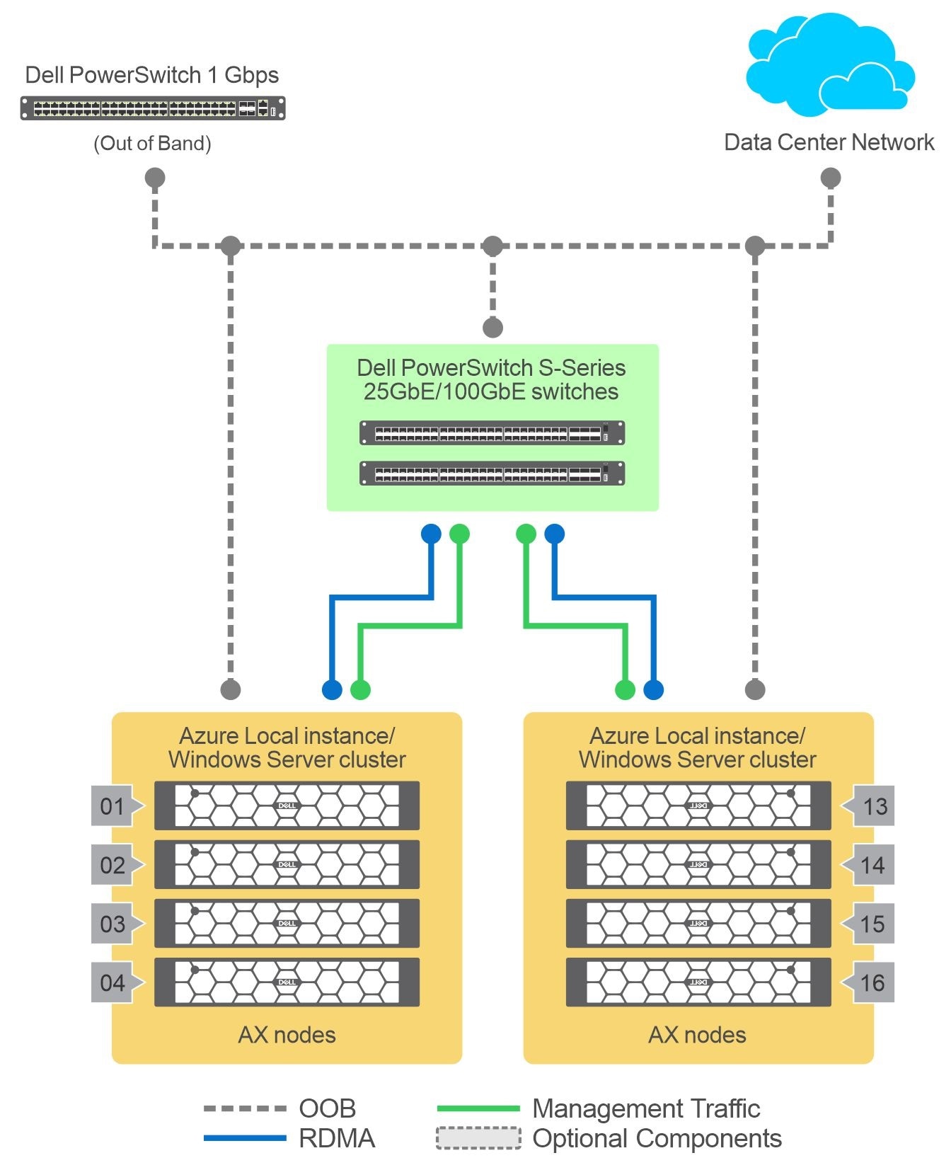
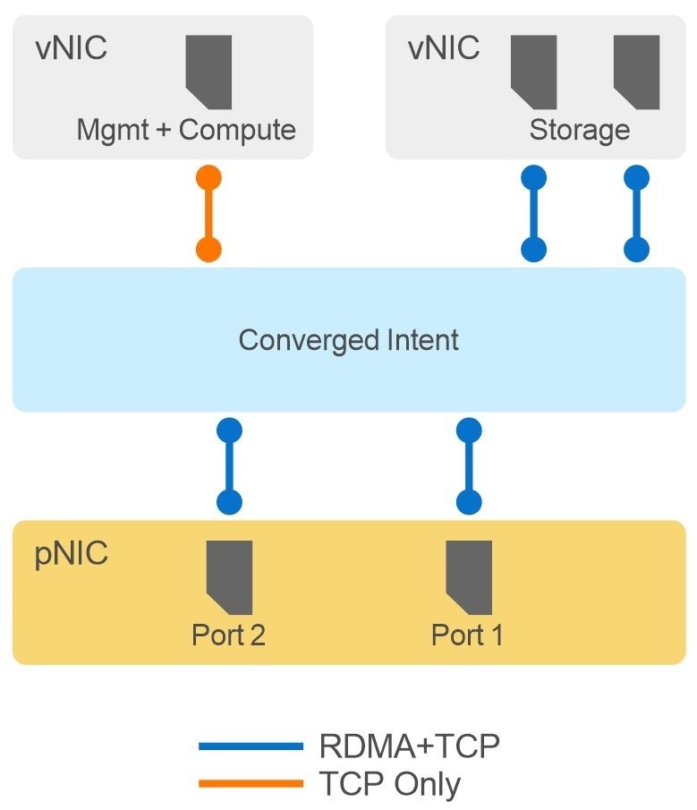
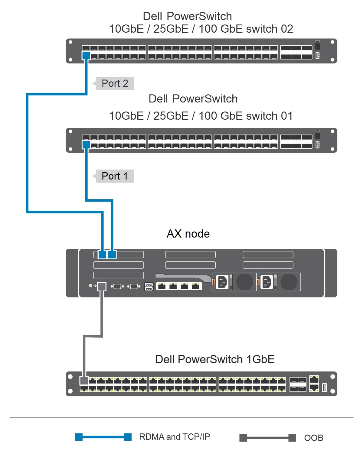
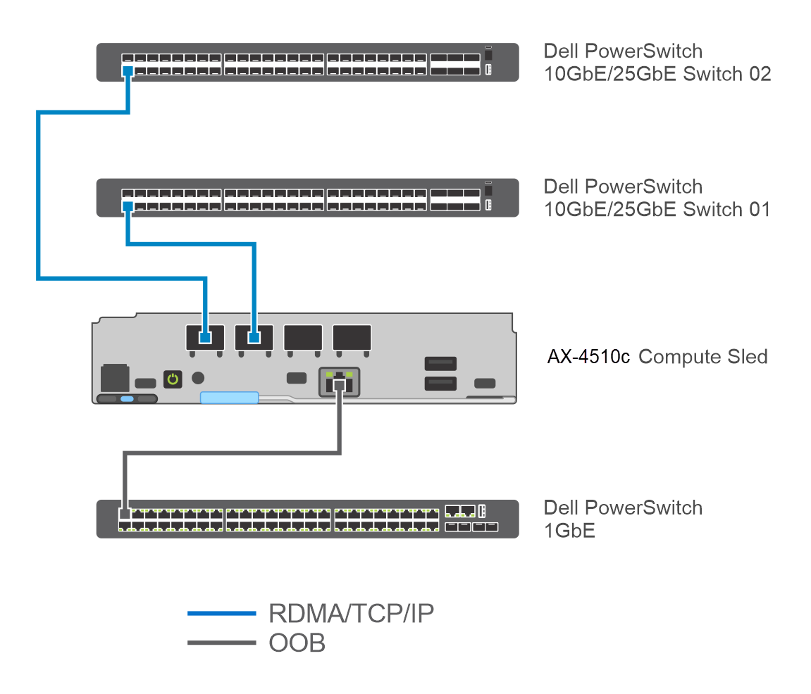
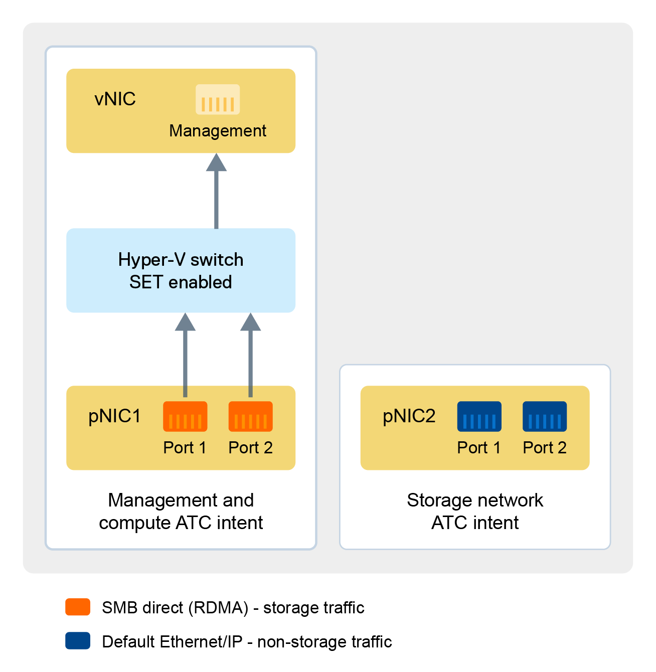
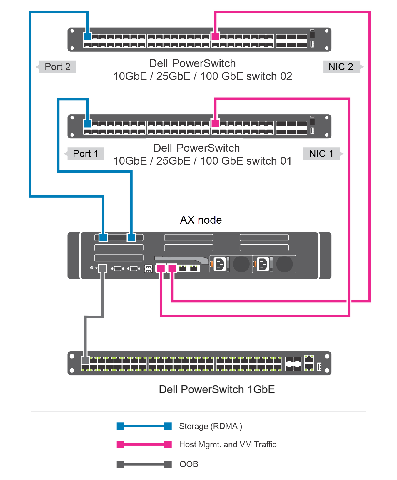
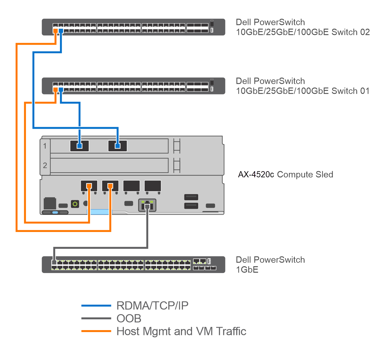
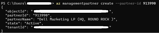

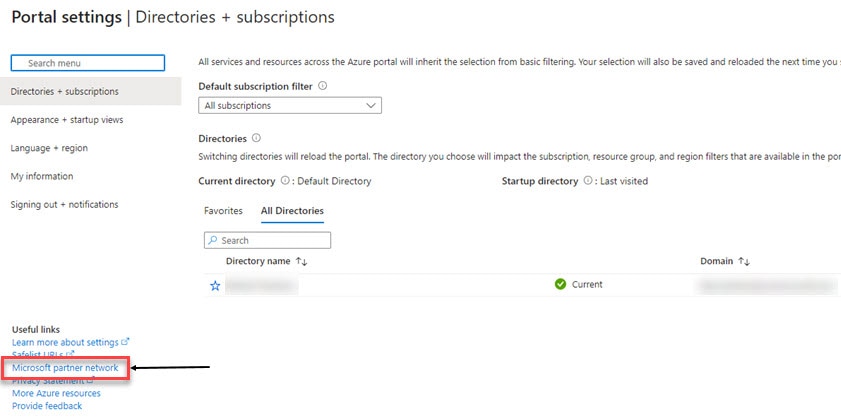
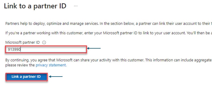

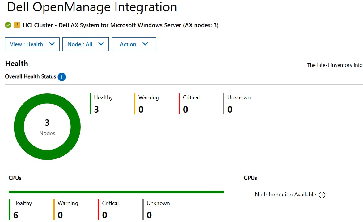
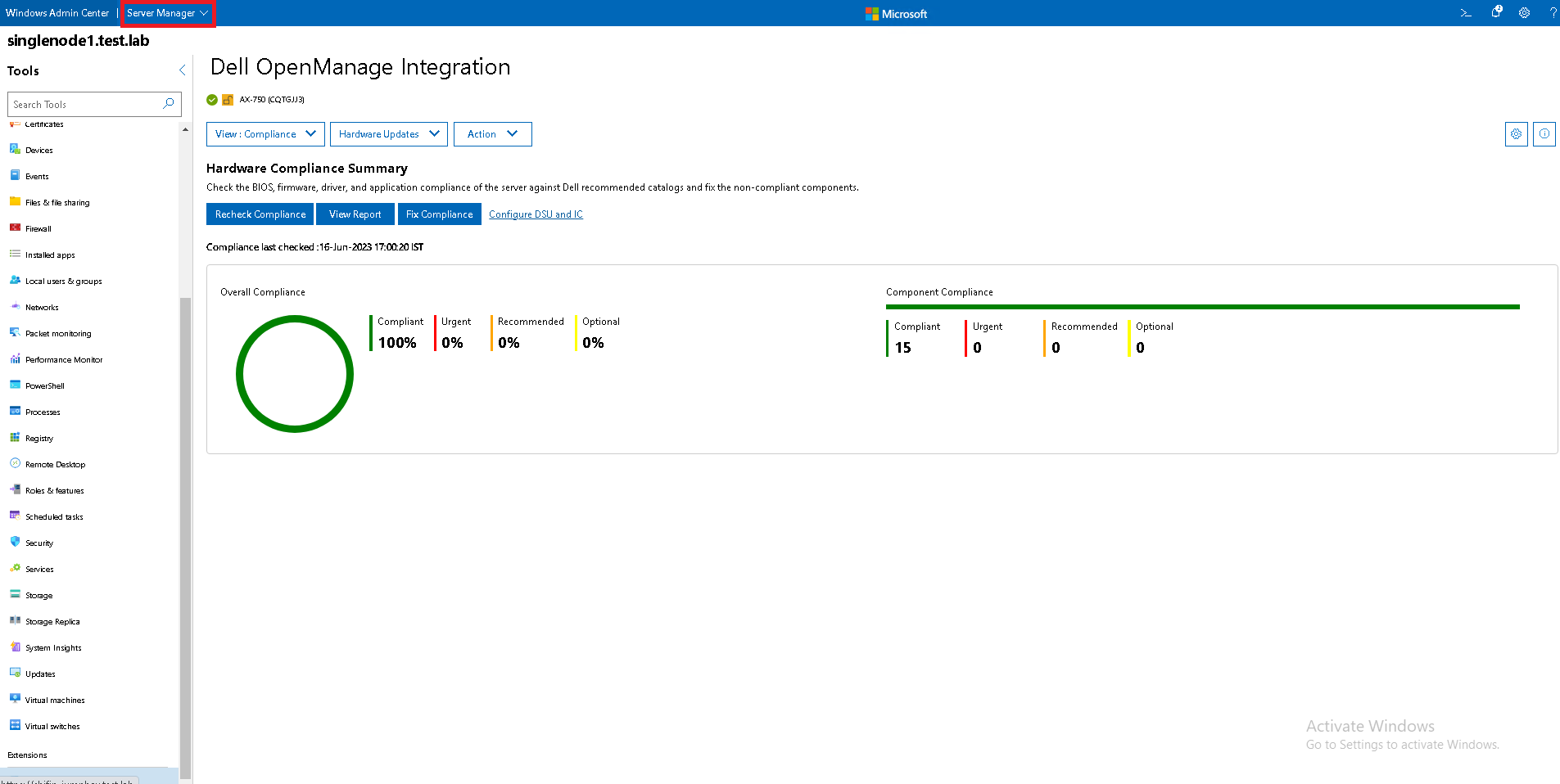
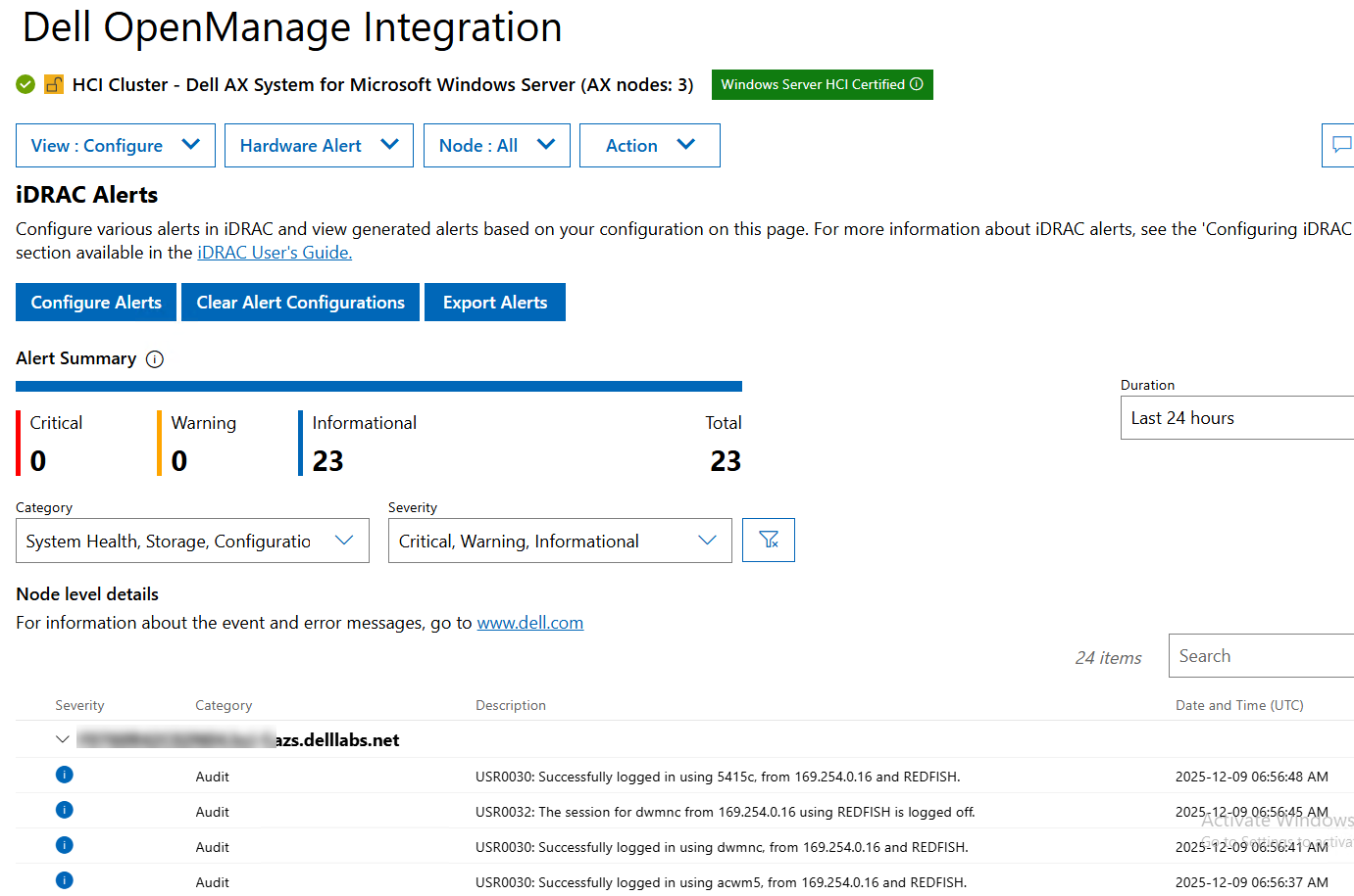
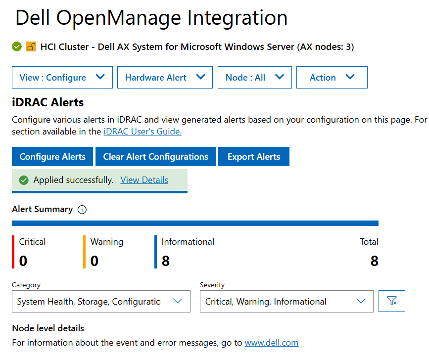
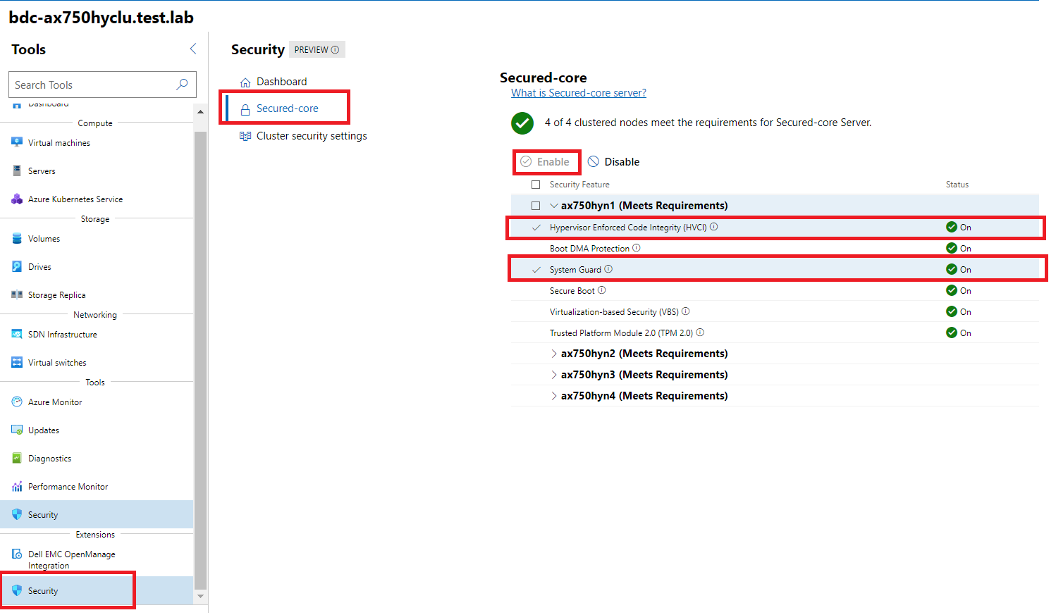
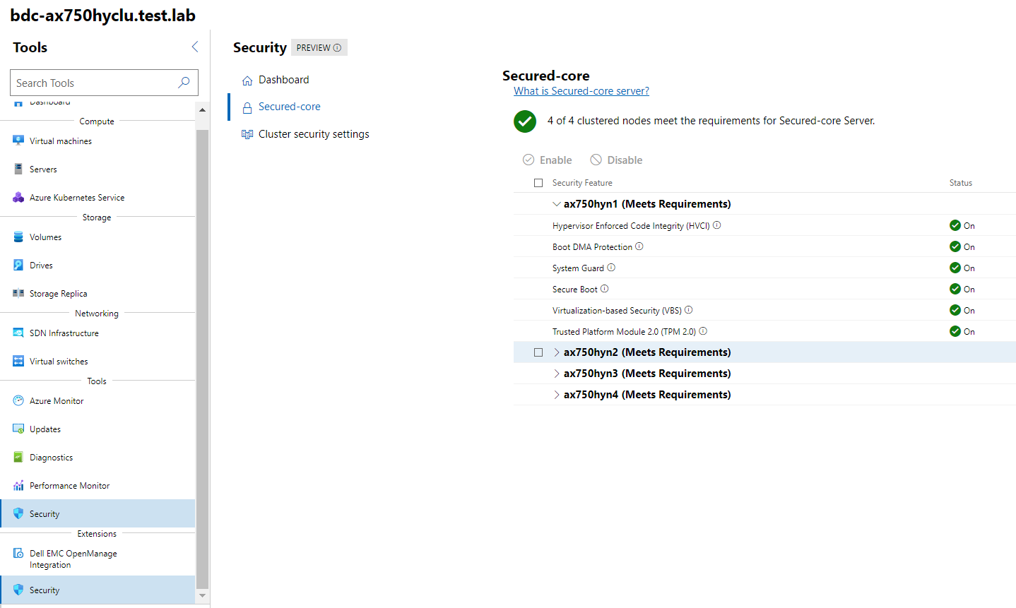
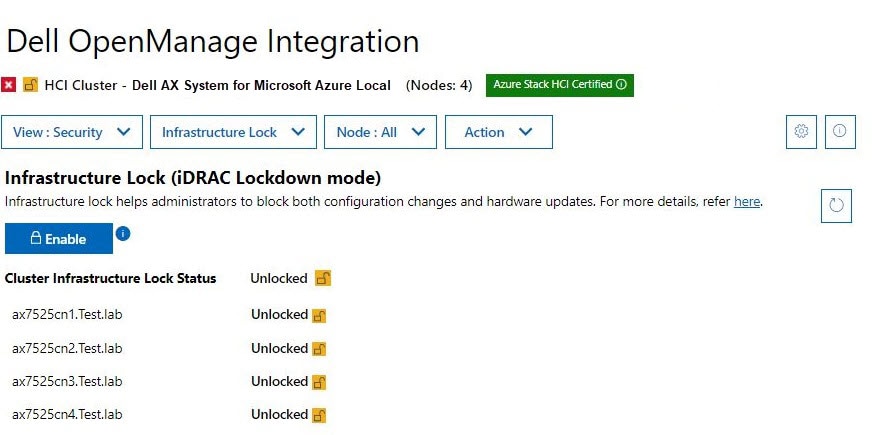
 Compliant: Shows all cluster nodes are compliant with all Dell policies.
 Errors: Shows if any cluster node is not compliant with Dell Hardware Symmetry policy.
 Warnings: Shows if any cluster node is not compliant with any optional policies.
 Unknown: Shows if any cluster node inventory could not be retrieved when the node is down or not reachable.