Article Number: 000137698
Running CE Mode (Diagnostic Mode) on the H625CDW / H825CDW / S2825CD Dell Laser Printers
Summary: How to enter and run Diagnostic Mode on the H625CDW, H825CDW and S2825CD Dell Laser Printers.
Article Content
Symptoms
Table of Contents:
- CE Mode (Diagnostic Mode)
- Booting into CE Mode
- IOT Diags
- Paper Feed Tests
- Digital Input Feed Sensor Tests
1. CE Mode (Diagnostic Mode)
On most models of Dell Laser Printers it is possible to boot them into a diagnostic mode, called CE Mode, in order to troubleshoot the internal components in the system.
CE mode is broken into several sections:
- Parameter: Provides a life counter for consumable components as well as a complete page count.
- ESS Diags: Tests functionality of electronic components and controller elements, such as Operator Panel functionality.
- Print Info: Provides detailed settings pages.
- Test Print: A large variety of colour test prints allowing you to diagnose each toner/toner developer individually as welll as testing alignment (print skew issues).
- IOT Diags: Digital Input - Tests individual Sensors (useful for diagnosing paper jams and other hardware failures).
- Digital Output - Test individual Motors and clutches (useful for diagnosing paper Jam and paper feed issues).
Back to Top
2. Booting into CE Mode
- Hold down the 4, 5, and 6 buttons while powering the printer on.
- When prompted for a password, press 2, 2, and then 5. Then select Printer Diag.
- The two most common uses for CE Mode will be running Digital Output Motor and Clutch Tests to determine jam issues.
Back to Top
3. IOT Diags
Digital Output:
Running Motor and Clutches on the H825CDW / H625CDW / S2825CDN for diagnosing Feed/Jam/abnormal noise issues:
- Select Printer Diag.
- Scroll down until IOT Diag is displayed and Select.
- Then select Digital Output.
- Set 041-001 to EXEC (ON) by pressing the Select (Tick) Button.
This Motor must be left at EXEC for the other motors to run correctly to allow accurate diagnosis.
Scroll Down to 071 061: Main Motor and Press Select (Tick) To Turn to Exec (ON)- You should now hear the main Motor.
 Note: To Turn off any Motor or Clutch press the X button.
Leave the Main Motor at EXEC and scroll down to the following Clutches and Turn on each in sequence, ensuring you stop each test before starting the next.
- 071 004 Regi Clutch
- 071 005 Exit Clutch
- 071 007 Duplex Clutch
- 071 014 Option Feeder 1 Feed Clutch
- 071 022 Option Feeder 1 Take Away Clutch
- 071 001 MSI Feed Solenoid
Each time you should hear a click as the clutch is turned on.
See Below for a list of Motor DO (Digital Output) Tests:
- Scroll down until IOT Diag is displayed and Select.
- Then select Digital Output.
- Set 041-001 to EXEC (ON) by pressing the Select (Tick) Button.
- Run each Motor individually to determine functionality.
- 042 061 Main Fan
- 071 061 Main Motor
- 071 065 Sub Motor
- 071 010 Option Feeder 1 Motor
- 071 017 Option Feeder 2 Motor (Only If an Optional Tray 2 is installed)
- 093 004 Yellow Toner Dispense Motor
- 093 006 Magenta Toner Dispense Motor
- 093 008 Cyan Toner Dispense Motor
- 093 010 Black Toner Dispense Motor
Digital Inputs:
Digital Input checks whether the digital input (DI) components function properly.
The display shows [0] when the digital input test is started, and the value will be increased when the DI components are switched from OFF to ON, which is used for confirming that the component functions normally.
The test targets all DI components (sensors).
See Below for a list of all DI (Digital Input) Tests:
- 010 200 Fusing Relay Enable
- 041 300 Inter Lock Side Cover
- 041 301 Inter Lock Rear Cover
- 071 100 MSI No Paper Sensor
- 071 101 Tray1 No Paper Sensor
- 071 103 Regi Sensor
- 071 104 Exit Sensor
- 071 109 Option Feeder 1 Size Sensor 0
- 071 110 Option Feeder 1 Size Sensor 1
- 071 111 Option Feeder 1 Size Sensor 2
- 071 112 Option Feeder 1 No Paper Sensor
- 071 116 Option Feeder 2 No Paper Sensor
- 071 117 Option Feeder 1 Path Sensor
- 071 200 Main Motor Alarm
- 071 201 Sub Motor Alarm
- 071 202 Option Feeder1 Motor Alarm
- 094 202 Waste Toner Box Full Sensor
Back to Top
4. Paper Feed Tests
In CE Mode you are also able to run manual feed tests, allowing us to accurately pinpoint the motor or component that is failing and causing a jam.
This is done by booting into CE Mode, as described above then:
- Select Printer Diag.
- Scroll down until IOT Diag is displayed and Select.
- Then select Digital Output.
- Set 041-001 to EXEC (ON) by pressing the Select (Tick) Button.
This Motor must be left at EXEC for the other motors to run correctly to allow accurate diagnosis.
Then turn on each Motor in sequence to feed the paper through the printer.
Tray 1 Feed Test
| Motor / Clutch | Normal Speed | Half Speed |
|---|---|---|
| Main Motor | 071-061 | 071-062 |
| Sub Motor | 071-065 | 071-066 |
| Regi Clutch | 071-004 | 071-004 |
| Exit Clutch | 071-005 | 071-005 |
| Tray 1 Feed Clutch | 071-002** | 071-002** |
** You will need to toggle this on and off Twice in order to feed a single sheet of paper.
MPF Fed Test
| Motor / Clutch | Normal Speed | Half Speed |
|---|---|---|
| Main Motor | 071-061 | 071-062 |
| Sub Motor | 071-065 | 071-066 |
| Regi Clutch | 071-004 | 071-004 |
| Exit Clutch | 071-005 | 071-005 |
| Take Away 2 Clutch | 071-003 | 071-003 |
| MSI Feed Solenoid | 071-001** | 071-001** |
** You will need to toggle this on and off Twice in order to feed a single sheet of paper.
To cancel motor Test hit back arrow twice.
CE Mode Test Prints
Test Pattern (No Image [IOT]):
The No Image [IOT] Test Pattern prints the IOT built-in blank page pattern on a side of paper (IOT print functionality check) (Figure 1).
Figure 1
Test Pattern (Test Pat 600 [IOT]):
The Test Pat 600 [IOT] Test Pattern prints the IOT built-in test pattern 600 dpi on a side of paper (IOT print functionality check).
Grid Pattern (Grid 2):
The ESS built-in Grid 2 Pattern (Grid2) prints the grid pattern on a side of paper (Figure 2).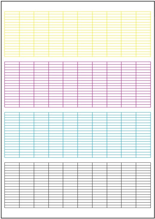
Figure 2
Cyan 20%:
The Cyan 20% (ESS built-in test pattern) fills one side of paper with 20% density cyan (Figure 3).
Figure 3
Magenta 20%:
The Magenta 20% (ESS built-in test pattern) fills one side of paper with 20% density magenta (Figure 4).
Figure 4
Yellow 20%:
The Yellow 20% (ESS built-in test pattern) fills one side of paper with 20% density yellow (Figure 5).
Figure 5
Black 20%:
The Black 20% (ESS built-in test pattern) fills one side of paper with 20% density black (Figure 6).
Figure 6
CMY 20%:
The CMY 20% (ESS built-in test pattern) fills one side of paper with 20% density of the mixture of cyan, magenta, and yellow (Figure 7).
Figure 7
Gradation:
The Gradation (ESS built-in test pattern) prints the broken border patterns with the density of 0 to 100% cyan, magenta, yellow, and black (Figure 8).
Figure 8
Toner Pallet Check:
The Toner Pallet Check (ESS built-in test pattern) prints four bars, filled with 100% density of each color (C/M/Y/K), lined on the paper.
Use this test for checking the density of each toner cartridge (Figure 9).
Figure 9
Contamination Check:
The Contamination Check prints 5 sheets of paper with the pattern of millimeter scale on the top/left edges and inch scale on the bottom/right edges, each filed with Y/M/C/K colour of 20% density, and the one with defect list (which helps finding defects such as lines, streaks, smudges, and scaling the size of the defect to identify the part to be replaced) (Figure 10).
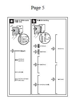
Figure 10
Back to Top
5. Digital Input Feed Sensor Tests
Digital Input checks whether the digital input (DI) components function properly.
A paper jam error may occur if one of the sensors are stuck or damaged.
The guide below shows the most likely sensors for any jam or feed issue and how to test functionality.
Registration Sensor:
DI: 071-103
The Registration Sensor identifies whether paper is jammed internally when pulled from the Tray or the MPF.
In order to test the Regi Sensor:
- Boot into CE Mode and go to the Digital Input Tests.
- Open the Back Cover.
- With the door open, the Regi Sensor can be seen on the bottom half of the Printer, shown below (Figure 11).

Figure 11
- The change will be registered in the following way:
L0 -> H0 -> L1 -> H1 -> L2 -> H2... (L: sensor closed, H: sensor open) - If the counter does not move up then there may be some damage to the sensor or the controller card in the printer.
If these steps do not correct the problem, please contact Dell Technical Support.

More information can be found in the User Guide for your model printer, or visit our Printer Support site for additional information, troubleshooting articles and videos.
Purchase Toner and other Dell Laser Printer Supplies
Dell Recycling
 It is recommended that only Dell Branded toner, drums, transfer rollers or other consumables are used in our laser printers. Dell cannot guarantee compatibility or the print quality of any 3rd party consumables.
Back to Top
Article Properties
Affected Product
Dell H625cdw Cloud MFP Laser Printer, Dell H825cdw Cloud MFP Laser Printer, Dell S2825cdn Smart MFP Laser Printer
Last Published Date
10 Apr 2021
Version
3
Article Type
Solution