Precision 3640 Tower and Precision 3640 XE Tower Customer Replaceable Unit (CRU) Part Removal Guide
Summary: Customer replaceable unit (CRU) parts may be removed from the Precision 3640 Tower and Precision 3640 XE Tower by following these instructions.
Symptoms
These guides take you step by step through the safe removal of what are considered to be the Customer Replaceable Unit (CRU) parts of a Precision 3640 Tower and Precision 3640 XE Tower. (CRUs are the parts of the computer that should not need an engineer to remove or replace.) The guides also include figures to reference what is involved.
Cause
Resolution
Table of Contents:
Removal Guide
If these guides do not cover what you are looking to do, then you want to reference your System Manual.
The article below provides information about safe practices to consider before working with electrical equipment.
Removal Instructions
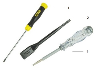
| 1 | Small Phillips head screwdriver | 2 | Plastic Scribe |
| 3 | Small Flat head screwdriver |
-
Pre-Removal Instructions Before removing the System Cover:
-
During installation or removal of any hardware, always ensure that all data is backed up properly.
-
Disconnect any telephone, network, or USB cables from the computer.
-
Disconnect the computer and all attached devices from their electrical outlets.
-
-
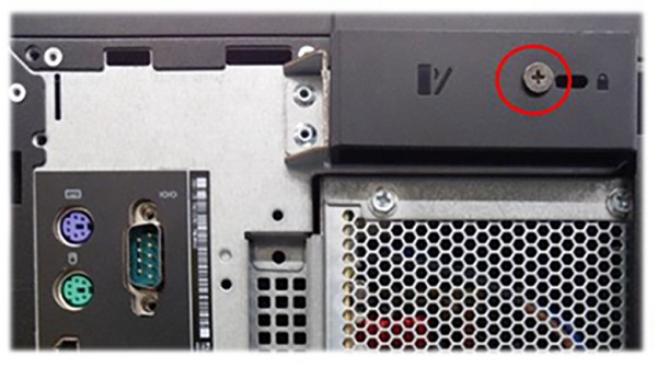
The release latch may have been secured with a security screw. Remove the security screw to release the cover.
-
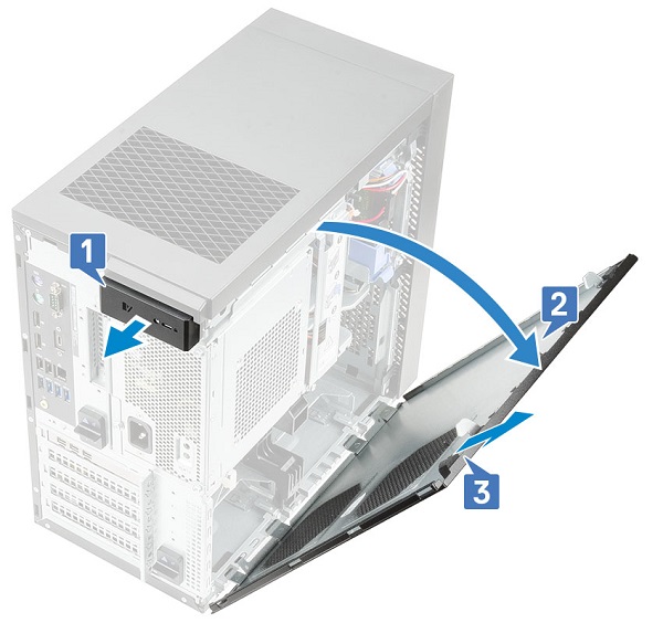
Pull the release latch [1], rotate the cover [2], and then lift the cover to remove it from the computer [3].
-
Pre-Removal Instructions Before removing the Front Bezel:
-
During installation or removal of any hardware, always ensure that all data is backed up properly.
-
Disconnect any telephone, network, or USB cables from the computer.
-
Disconnect the computer and all attached devices from their electrical outlets.
-
Remove the System cover.
-
-
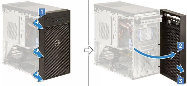
Lift the retention tabs [1], then rotate [2] and pull [3] the front bezel from the slots on the chassis.
-
Pre-Removal Instructions Before removing the 3.5-Inch Hard Disk Drive:
-
During installation or removal of any hardware, always ensure that all data is backed up properly.
-
Disconnect any telephone, network, or USB cables from the computer.
-
Disconnect the computer and all attached devices from their electrical outlets.
-
Remove the System cover.
-
-
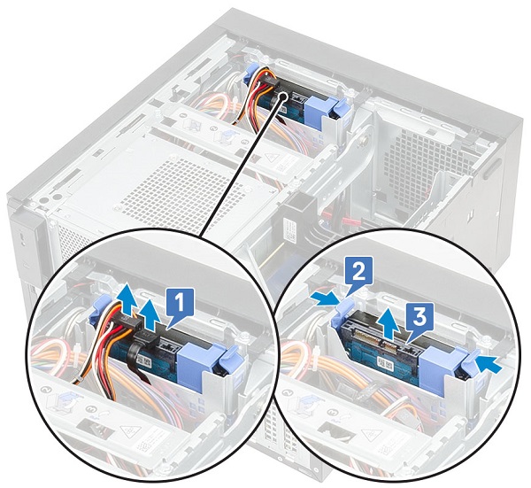
Disconnect the data cable and the power cable from the hard drive [1].
-
Press the blue securing bracket tabs [2] and lift the hard drive bracket out of the hard drive bay [3].
-
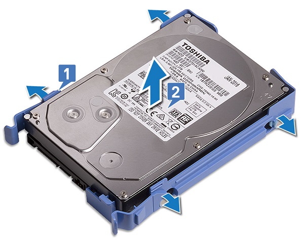
Flex the hard drive bracket [1] and lift the hard drive from the hard drive bracket [2].
-
Pre-Removal Instructions Before removing the 2.5-Inch Hard Disk Drive:
-
During installation or removal of any hardware, always ensure that all data is backed up properly.
-
Disconnect any telephone, network, or USB cables from the computer.
-
Disconnect the computer and all attached devices from their electrical outlets.
-
Remove the System cover.
-
-
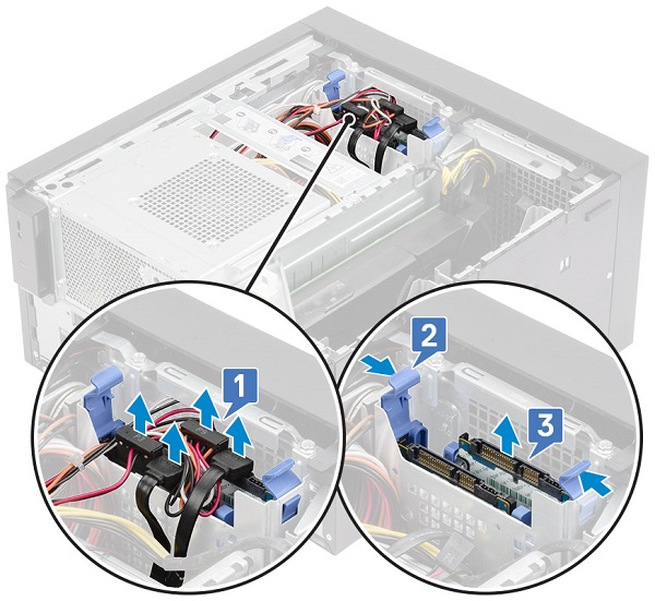
Disconnect the data cables and the power cables from the respective connectors on the hard drives [1].
-
Press the blue securing bracket tabs [2] and lift the hard drive bracket out of the hard drive bay [3].
-
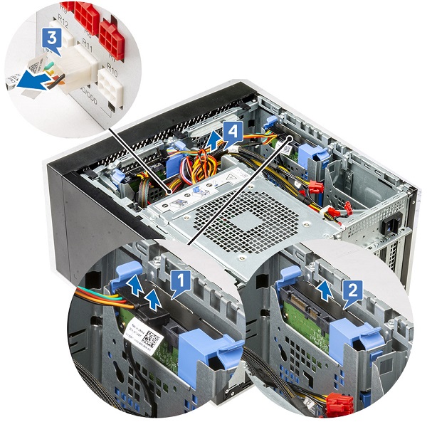
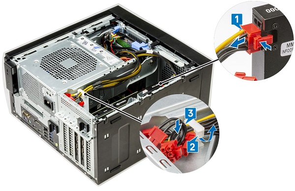
Disconnect the data cables and the power cables from the respective connectors on the hard drives [1].
-
Press the blue securing bracket tabs and lift the hard drive bracket out of the bottom hard drive bays [2].
-
Disconnect the SATA power cable from the connectors on the PSU [3].
-
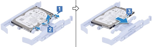
Flex the hard drive bracket [1], lift the hard drive [2], and then slide out from the hard drive bracket [3].
-
Pre-Removal Instructions Before opening the PSU hinge:
-
During installation or removal of any hardware, always ensure that all data is backed up properly.
-
Disconnect any telephone, network, or USB cables from the computer.
-
Disconnect the computer and all attached devices from their electrical outlets.
-
Remove the System cover.
-
-
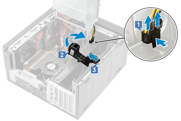
Unlock the PSU release latches [1, 2].
-
Rotate the PSU hinge as shown in the figure [3].

-
Pre-Removal Instructions Before removing the Expansion Cards:
-
During installation or removal of any hardware, always ensure that all data is backed up properly.
-
Disconnect any telephone, network, or USB cables from the computer.
-
Disconnect the computer and all attached devices from their electrical outlets.
-
Remove the System cover.
-
-
Disconnect the VGA power cable from the graphics cards in a dual graphics card configuration [1].
-
Lift the plastic latch to free the cables [2] and remove the cables from the tabs [3].
-
Open the PSU hinge.
-
Press the releasing clip and disconnect the graphics-card power cable from the connector on the graphics card [1].
-
Lift the side of the PCIe holder that sits on the graphics card [2].
-
Slide the PCIe holder to release the tab on the PCIe holder from the slot on the chassis [3].
-
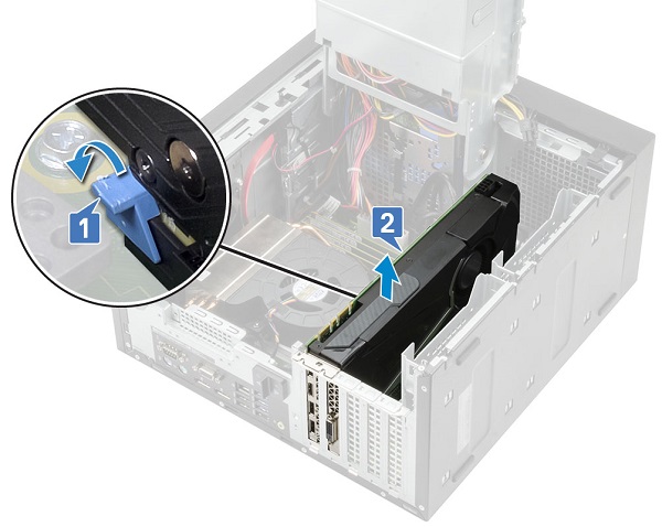
Push the card retention latch away from the card [1] and lift the graphics card out of the computer [2].
-
Pre-Removal Instructions Before removing the Memory:
-
During installation or removal of any hardware, always ensure that all data is backed up properly.
-
Disconnect any telephone, network, or USB cables from the computer.
-
Disconnect the computer and all attached devices from their electrical outlets.
-
Remove the System cover.
-
-
Press the memory module retention tabs on each side of the memory module.
-
Lift the memory module out of the connectors on the system board.
-
Pre-Removal Instructions Before removing the Coin Cell Battery:
-
During installation or removal of any hardware, always ensure that all data is backed up properly.
-
Disconnect any telephone, network, or USB cables from the computer.
-
Disconnect the computer and all attached devices from their electrical outlets.
-
Remove the System cover.
-
Open the PSU hinge.
-
-
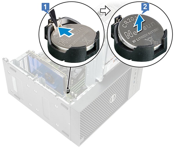
Press the release latch until the coin-cell battery pops out [1].
-
Remove the coin-cell battery from the connector on the system board [2].
-
Pre-Removal Instructions Before removing the Internal Speakers:
-
During installation or removal of any hardware, always ensure that all data is backed up properly.
-
Disconnect any telephone, network, or USB cables from the computer.
-
Disconnect the computer and all attached devices from their electrical outlets.
-
Remove the System cover.
-
Open the PSU hinge.
-
-
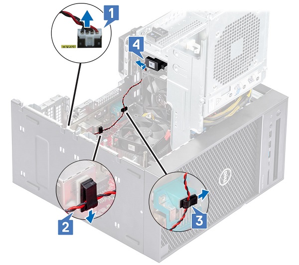
Disconnect the speaker cable from the system board [1].
-
Remove the speaker cable from the tabs on the system board [2, 3].
-
Press the release tab and pull the speaker out from the front of the system chassis [4].
-
Pre-Removal Instructions Before removing the Intrusion Switch and Cable:
-
During installation or removal of any hardware, always ensure that all data is backed up properly.
-
Disconnect any telephone, network, or USB cables from the computer.
-
Disconnect the computer and all attached devices from their electrical outlets.
-
Remove the System cover.
-
Remove the Front bezel.
-
Open the PSU hinge.
-
-
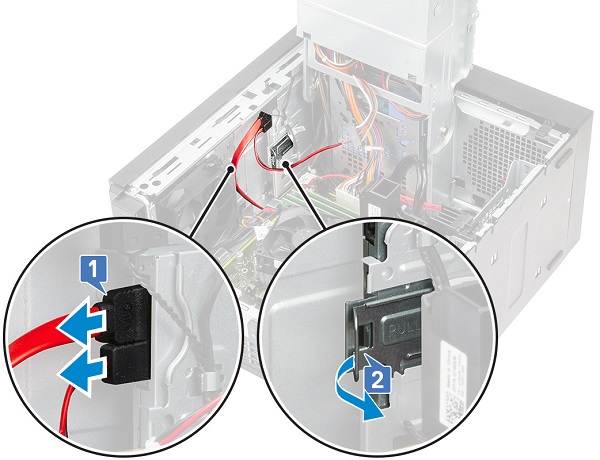
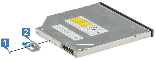
Disconnect the data cable and the power cable from the optical drive [1].
-
Hold and pull the optical drive latch to unlock the optical drive [2].
-
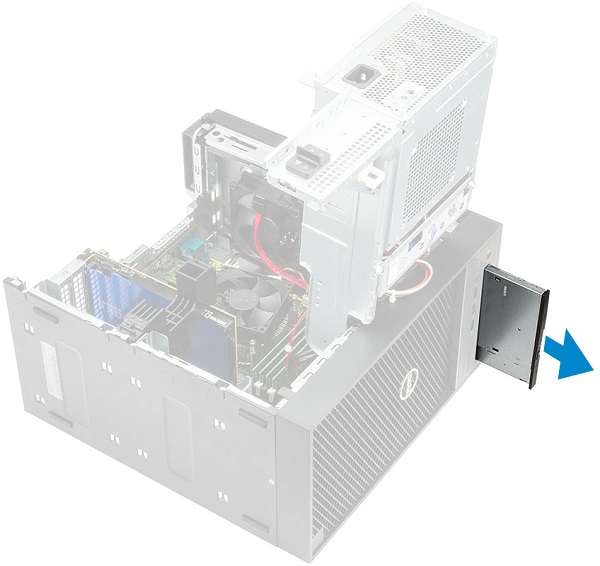
Slide the optical drive from the front of the computer.
-
Remove the M2x2.5 screw that secures the optical-drive bracket to the optical drive [1] and remove the optical drive bracket [2].
-
Pre-Removal Instructions Before removing the WLAN module and SMA antenna:
-
During installation or removal of any hardware, always ensure that all data is backed up properly.
-
Disconnect any telephone, network, or USB cables from the computer.
-
Disconnect the computer and all attached devices from their electrical outlets.
-
Remove the System cover.
-
Open the PSU hinge.
-
-
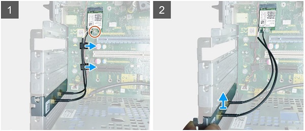
Remove the single M2x3.5 screw that secures the WLAN card to the system board, then remove the antenna cables from the rubber guides on the system board [1].
-
Slide and remove the external antenna connector from the PCIe slot on the chassis [2].
-
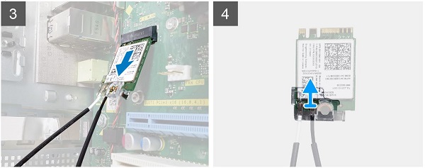
Remove the WLAN card from the system board [3].
-
Remove the plastic bracket from the top of the antenna connector [4].
-
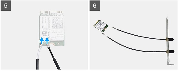
Gently remove the antenna cable from the connectors on the WLAN card [5].
-
Separate the WLAN module and SMA antenna [6].
-
Pre-Removal Instructions Before removing the I/O card:
-
During installation or removal of any hardware, always ensure that all data is backed up properly.
-
Disconnect any telephone, network, or USB cables from the computer.
-
Disconnect the computer and all attached devices from their electrical outlets.
-
Remove the System cover.
-
Remove the Front bezel.
-
Remove the Optical drive.
-
Open the PSU hinge.
-
-
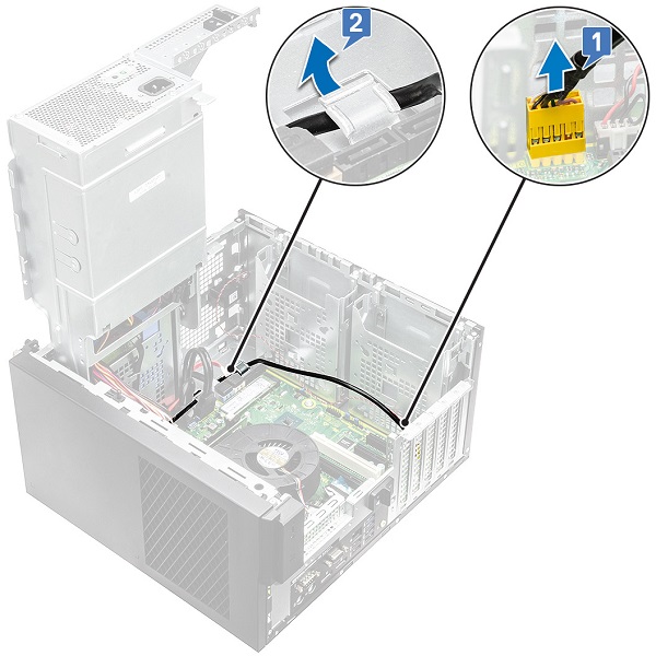
Disconnect the I/O audio cable from the connector on the system board [1] and remove the cable from the routing guides next to the system board on the chassis [2].
-
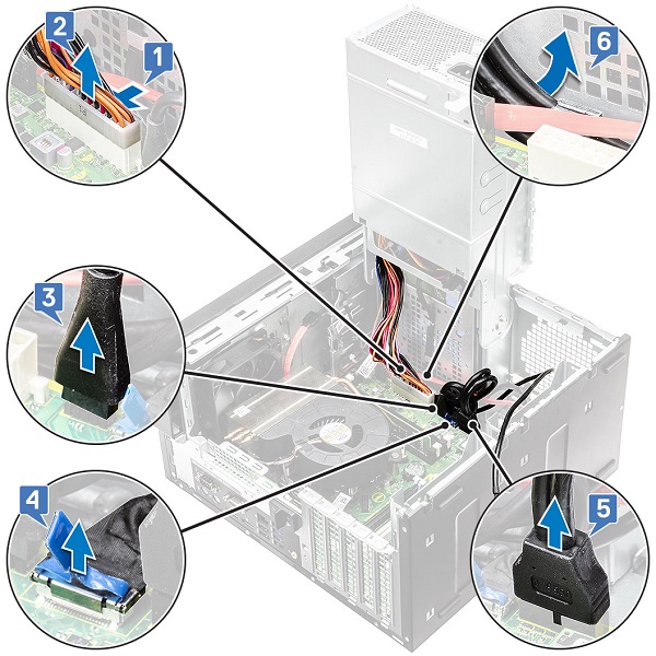
Disconnect the following cables from their respective connectors on the system board:
- System board power connector cable [1, 2]
- SD card cable [3]
- Type-C cable [4]
- I/O USB cable [5]
- Remove the cables from the connector [6]
-
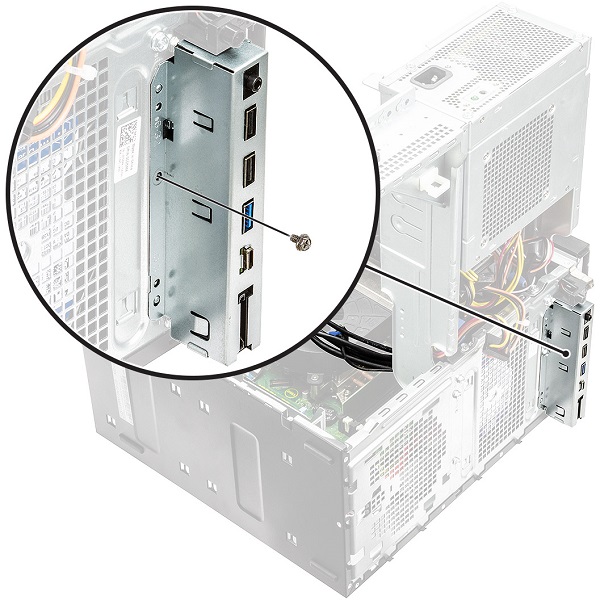
Remove the #6-32x1/4" screw that secures the I/O panel to the chassis.
-
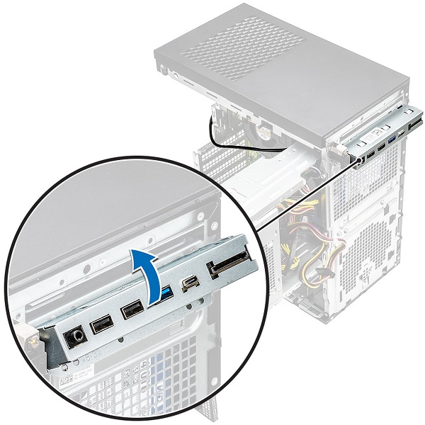
Lift the I/O panel to release the tabs on the I/O panel from the slots on the chassis.
-
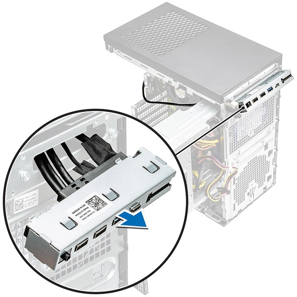
Pull the I/O panel along with the cables to remove it from the I/O panel slot on the chassis.
-
Pre-Removal Instructions Before removing the I/O card:
-
During installation or removal of any hardware, always ensure that all data is backed up properly.
-
Disconnect any telephone, network, or USB cables from the computer.
-
Disconnect the computer and all attached devices from their electrical outlets.
-
Remove the System cover.
-
Open the PSU hinge.
-
-
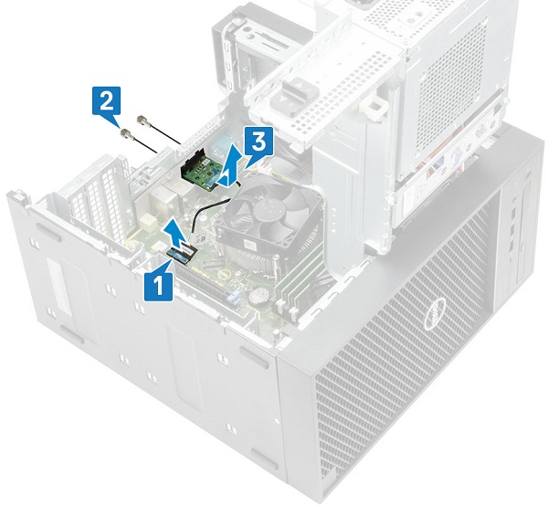
Disconnect the I/O card cable from the connector on the system board [1].
-
Remove the two M3X3 screws that secure the I/O card to the system [2].
-
Remove the I/O card from the system [3].
-
Pre-Removal Instructions Before removing the SD Card:
-
During installation or removal of any hardware, always ensure that all data is backed up properly.
-
-
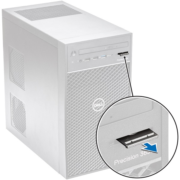
Pull the SD card out of the system.
-
Pre-Removal Instructions Before removing the Feet:
-
During installation or removal of any hardware, always ensure that all data is backed up properly.
-
Disconnect any telephone, network, or USB cables from the computer
-
Disconnect the computer and all attached devices from their electrical outlets
-
-
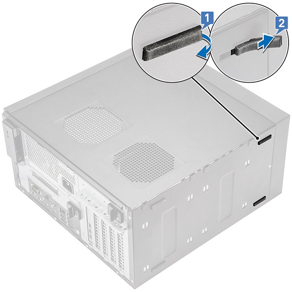
Pull one end of the rubber feet out of the slot [1] and slide the rubber feet to remove it from the system [2].
| If you require further assistance, contact technical Support. | |
| Contact Us | Go back to the System Type teardown contents page |