Application Modernization for High-Volume Workloads with DataStax
Executive summary
Summary
Technological advances are bringing new data-capture and analysis capabilities to enterprises. But the reliance on legacy applications and outdated data models can hamper these capabilities, especially in finance and banking. Many enterprises are embracing application modernization to help them use new technologies, but they might find that relational data models are a limiting factor.
DataStax Enterprise can help enterprises use today’s expanding datasets to provide applications with access to more data and better insights. Built on Apache Cassandra, DataStax Enterprise overcomes many of the limitations of rigid relational databases by handling various structured, semistructured, and unstructured datatypes. Also, DataStax Enterprise provides a high-performance foundation for high-velocity data consumption and retrieval that can span multiple data centers, including those data centers that are geographically dispersed.
In this white paper, we show how DataStax Enterprise fits into the application-modernization puzzle, and how DataStax Enterprise performs in a cloud-native environment with Kubernetes platforms such as Red Hat OpenShift and VMware Tanzu Kubernetes Grid (VMware Tanzu), all running on Dell EMC PowerEdge servers.
Introduction
Data is the engine that drives today’s business. Advances in technology have given enterprises the ability to capture more data than ever before, from real-time data generated by thousands or even millions of Internet of Things (IoT) devices to customer-data generated by social-media advertising campaigns. Yet the exponential growth of data and the reliance on legacy data models can hamper growth and negatively impact data-driven organizations. Traditional relational database management systems (RDMSs) have a proven track record of providing critical answers to business questions when data is highly structured. But data models that rely on rigid schemas can be a hindrance as more data becomes unstructured. The breadth and depth of data sources require systems that can handle various datatypes, such as text, documents, images, and video.
DataStax Enterprise, built on Apache Cassandra, offers a scalable, highly available NoSQL database solution that can be scaled on premises and across data centers, cloud providers, and regions. The distributed nature of DataStax Enterprise means that organizations can deploy fault-tolerant databases that can manage high-velocity unstructured and semistructured data while providing high performance and 100 percent uptime. Dell Technologies, Intel, and DataStax have partnered to provide organizations with highly available and security-enabled Apache Cassandra solutions that can handle the largest data growth and the greatest processing needs across most industries.
This white paper discusses the following topics:
- The challenges of application modernization and managing large datasets
- How DataStax Enterprise can help organizations modernize legacy applications and manage increasing data volumes
- A brief overview of the Apache Cassandra architecture, DataStax Enterprise cluster management, and the DataStax Kubernetes Operator for Apache Cassandra (Cass Operator)
- A DataStax Enterprise solution architecture that Dell Technologies, Intel, and DataStax used to test DataStax Enterprise performance
- The results of the DataStax Enterprise performance test
Intended audience
This white paper is intended for data center managers and IT architects who are involved with engineering, operations, or planning for database selection and infrastructure design, and particularly for personnel considering application modernization using containerization of databases like Apache Cassandra.
We value your feedback
Dell Technologies and the authors of this document welcome your feedback on the solution and the solution documentation. Contact the Dell Technologies Solutions team by email or provide your comments by completing our documentation survey.
Authors: This document was written jointly by DataStax, Dell Technologies, and Intel, by the Engineering and Technical Marketing teams for data analytics
Note: For links to additional documentation for this solution, see the Dell Technologies Solutions Info Hub for Data Analytics.
The promise of application modernization
Introduction
Enterprises have long relied on the latest technologies to manage all aspects of their organizations, from operations to supply chains, and from human resources to customer management. But as technology becomes obsolete, legacy enterprise applications become more difficult to maintain and scale.
Application modernization is the process of applying new technology and modern development methodologies to legacy systems. Modernization projects can range from refreshing the platforms that applications use to completely rewriting applications using modern architectures, tools, and development processes.
Many legacy applications—including those applications that were written for mainframe computers—were written as single, large, monolithic units. These applications often run on proprietary hardware in on-premises data centers, and they rely on teams of developers, project managers, quality assurance (QA) staff, and operations personnel to develop, deploy, and maintain the applications. Although mainframe applications, for example, are known for their stability and availability, maintaining these applications is expensive and time-consuming. Also, the functionality of legacy applications typically cannot be repurposed for use in other areas of an organization.
Given the difficulties inherent in developing and maintaining their older applications, enterprises are increasingly turning to microservices architectures to enhance and scale their critical applications. A microservices architecture takes a different approach to application design and development. Legacy applications often contain valuable functions and intellectual property that are locked deep within the application. A set of functions might work well within a certain context within the application, but they could also prove valuable across other areas of the enterprise. A microservices approach breaks applications down into independent components that are developed, deployed, and maintained as separate units. These components are often simpler to maintain and deploy, and they can also be reused.
Application containerization can help bridge the continued reliance on legacy applications while simultaneously providing the foundation for modern application development. Containers are lightweight, portable, stand-alone packages that encapsulate the software, runtime libraries, tools, and settings that are required to run an application or microservice. Using a container engine such as Docker, multiple containers can run on a physical server, but they are isolated from other containers and the server’s operating system. This isolation helps applications and microservices avoid software, driver, or library incompatibilities.
While the combination of containers and microservices provides a path to application modernization, managing and orchestrating container deployments is vital. Containerized applications built using a microservices architecture can help enterprises scale, in addition to allowing the applications and data to become more distributed in nature. Kubernetes, an open-source container-orchestration system, can streamline the deployment, scaling, and management of containers. For example, a containerized, distributed, microservices-based application can be deployed on premises using off-the-shelf Intel Xeon processor-based hardware, such as Dell EMC PowerEdge servers; it can be deployed to a cloud platform such as Microsoft Azure; or it can be deployed in a hybrid-cloud environment. Software developers can use Kubernetes to automate the full life cycle of containerized microservices.
Another benefit of containerized microservices is that they can be run from any location, such as on-premises data centers or geographically dispersed cloud platforms. Yet the benefits of containerized microservices can lead to scalability and performance issues if the underlying data models are not also modernized.
The challenges of distributed data
While a microservices architecture can help transform legacy applications into modern, scalable applications, another challenge of application modernization is designing a distributed database model that can span data centers, provide high availability, and deliver high-performance data processing capabilities.
Apache Hadoop, a scalable data-storage and analytics system, provides a model for storing and processing large, distributed datasets. The architecture of Apache Hadoop is distributed, meaning that data is distributed across multiple nodes. These clusters of Apache Hadoop nodes can be in a single data center, or they can span multiple data centers.
While Apache Hadoop paved the way for large-scale analytics across large, distributed datasets, it is better suited for batch processing than for real-time analysis of unstructured data. NoSQL databases, such as Apache Cassandra, fill the gap for real-time storage and analysis of high-velocity unstructured, semistructured, and structured data.
Like Apache Hadoop, NoSQL databases can scale horizontally to provide fast read/write access to various datatypes. Apache Hadoop and NoSQL databases differ in that Apache Hadoop is not intended to be a database-management system (DBMS); rather, it is designed to store and analyze massive amounts of unstructured data. NoSQL databases share the same ability as Apache Hadoop to store and analyze large, distributed datasets. Additionally, NoSQL databases are also designed to store and analyze unstructured, semistructured, and structured data.
The flexibility and variety of NoSQL databases and data models provide an answer to the inherent limitations of relational databases. Data models designed for relational databases have historically contained rigid schemas. While these rigid schemas have served enterprises well for decades, new data sources are pushing the limits of relational database designs. Data sources can now generate data with various structures that do not follow any specification, data model, or organization. Examples of unstructured data include raw sensor data from IoT devices and hand-written patient information created by medical professionals. Semistructured data typically contains tags or markers within the data that identify information, but the data does not comply with a specific relational database schema. Examples of semistructured data include Extensible Markup Language (XML) or JavaScript Object Notation (JSON) documents and email messages.
To avoid the limitations of relational databases, structured and unstructured data must be modeled differently when using a NoSQL database. NoSQL data models include:
- Key-value store—This data model is one of the simplest NoSQL data models. A key-value database stores data as a set of key-value pairs, where the key is a unique identifier. Data within a key-value store can be easily partitioned to allow horizontal scaling. For example, web applications can use key-value stores to manage session information. The key in this example identifies the user, while the values can be user information, user preferences, discounts, or promotions.
- Wide-column store—This data model is similar to relational databases in that data is stored in rows, with each row of data consisting of columns. In a relational database, each column is rigidly defined and maintained across each row of data. For example, in an industrial or manufacturing scenario, a row of data from an IoT refrigeration sensor might contain the sensor’s device ID, the time, the date, and the temperature. Wide-column stores differ in that each row of data can contain a different number of columns, different column names, and different column datatypes than other rows in the same table. Using the IoT refrigeration sensor example, a wide-column store might store the device ID, temperature, and humidity data from a warehouse refrigeration sensor on one row. The data from another device that monitors refrigeration on a truck might include device ID, temperature, humidity, latitude, longitude, and speed on the next row. The wide-column store can capture rows of information from both devices in the same table, even though the columns vary.
- Document store—A document store is designed to store documents that are typically formatted as JSON documents. Like other NoSQL data models, a document store does not adhere to a defined schema. Rather, the structure is internal to the document itself. For example, a health sciences research system can use a document store to consolidate patient data and doctor consultation notes from an electronic health records (EHR) system. Data scientist can then query these records to discover health trends within the consultation notes and correlate them with various patient attributes.
- Graph databases—This data model uses graph structures to represent relationships. Graph databases are ideal for capturing relationships between different data artifacts. For example, financial institutions can use graph databases to analyze the relationships between people, bank accounts, and transactions to discover fraudulent behavior.
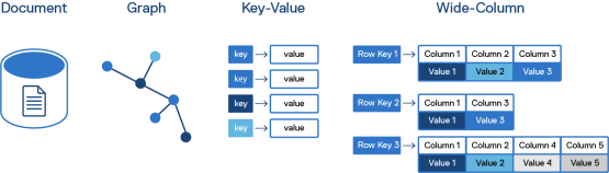
Figure 1. Four NoSQL database models
Enterprises with unstructured, semistructured, and structured data can now rely on NoSQL databases to enable modern microservices-enabled applications that meet the needs of diverse organizations and customers with many different data models.
DataStax Enterprise overview
Introduction
DataStax Enterprise employs Apache Cassandra, a wide-column NoSQL database that helps enterprises meet the challenges of today’s large, high-velocity datasets. The wide-column design of Apache Cassandra also gives it the ability to service other NoSQL data-model types, such as key-value store and document store.
As a scale-out data-management platform, DataStax Enterprise provides the high-performance and high-availability capabilities of Apache Cassandra with enterprise-grade deployment, security, and management tools. The decentralized, peer-to-peer architecture of DataStax Enterprise also lends itself well to distributed applications and linear scalability for large datasets.
Because DataStax Enterprise was designed for high performance, high availability, and high-velocity data, its use has grown across a number of vertical markets. Companies within healthcare, entertainment, retail, travel, finance, and banking all rely on DataStax Enterprise to provide real-time insights, fast response times, and security for their customers and employees.
DataStax Enterprise enables application modernization in finance and banking
DataStax Enterprise is particularly well suited to organizations within finance and banking. As more customers continue to choose online financial services over their brick-and-mortar counterparts, the ability to achieve customer-focused personalization, virtually zero downtime, and a lower total cost of ownership (TCO) is key to success.
Financial and banking organizations have relied on mainframes to provide services for both their customers and their employees for decades. Yet mainframes were not originally designed to interact with customer-facing applications. As old technology collides with new technology, mainframes are being pressed to work harder, and in ways for which they were not designed. Banking customers now expect their data to be instantly available, whether from a smartphone, tablet, or laptop. Trading analysts expect market data to be available in real time. This change means that financial and banking data models must support write-intensive, read-intensive, balanced read/write, and high-performance characteristics.
Application modernization in finance and banking entails four key traits:
- Cost savings—Because mainframe usage fees consist of a significant percentage of mainframe TCO, IT organizations within finance and banking are looking for ways to reduce their reliance on mainframes for customer-facing applications while still giving their customers a highly personalized experience. Offloading customer-facing application interactions lowers mainframe use, which can lead to cost savings.
- Ability to capture and act on large amounts of data in real time—Financial and banking organizations generate and consume massive amounts of data, from recording customer financial transactions to gathering real-time market data that trading analysts and customers can use. DataStax Enterprise is well suited for capturing and writing large amounts of data in real time. Captured data can then be quickly and automatically analyzed, giving trading analysts and customers fast access to critical financial information.
- Historical data storage—Both customers and financial analysts require access to vast amounts of historical financial data, whether it be transactions for banking customers or historical financial data for publicly traded companies. This data needs to be immediately accessible, while the data storage and analysis platform needs to be flexible as customer demands and datatypes continue to evolve. DataStax Enterprise can store and read these vast amounts of data using its distributed data model, which gives analysts and customers immediate access to the information that they need.
- Personalization—Today’s financial services and banking customers are more involved in their financial planning than ever before—from tracking how they spend money to planning for retirement. Providing insights into their finances requires both batch and real-time analytics that are simple to use. Also, financial analysts need to have access to up-to-the-second market information and analysis. DataStax Enterprise can provide financial analysts and banking customers quick access to their personalized data while also giving them the ability to make split-second market decisions.
The peer-to-peer architecture built into DataStax Enterprise enables it to scale data processing elastically, meaning that it can ingest and process data across any number of nodes and data centers. Also, DataStax Enterprise integrates with tools such as Apache Spark, which provides near-real-time processing of data streams, and new Storage-Attached Indexing (SAI) index technologies for search and indexing. As a platform, DataStax Enterprise functions as a hybrid transactional/analytical processing (HTAP) architecture by transparently replicating data across Apache Cassandra nodes without requiring costly and complex extract, transform, and load (ETL) processes to move data between the nodes. This replication allows individual nodes to access data instantly, while Apache Spark and SAI provide analytics and search capabilities.
DataStax Enterprise also provides the following enterprise-grade features, which can help companies modernize their applications:
- Advanced security—DataStax Enterprise provides security features such as unified authentication and role management; integration with Kerberos, Lightweight Directory Access Protocol (LDAP), and Microsoft Active Directory; data auditing that tracks user access to records, in addition to data changes; row-level access control that restricts to which rows of data a user has access; private schemas that restrict schema visibility; role-based auditing; and separation of duties, which can give administrators full database control while restricting data visibility.
- High performance—The Apache Cassandra storage engine in DataStax Enterprise can store multiple data models, such as JSON, tabular data, graph data, and key-value data. The storage engine also avoids reading data before writing, which dramatically reduces read performance latencies and data collisions.
- Distributed high availability—DataStax Enterprise uses the fault-tolerant storage system and fault detection in Apache Cassandra to provide high availability. Redundant data is automatically replicated among Apache Cassandra cluster nodes that can be located across multiple geographic locations. If a node fails, Apache Cassandra replicates the failed node’s data to the failed node’s replacement from neighboring cluster nodes.
- Extensibility—DataStax Enterprise supports a wide range of programming languages that developers can use to create applications, including C/C++, C#, Java, and Python. Stargate, an open-source API framework from DataStax, allows multiple APIs to access Apache Cassandra. DataStax Enterprise also supports creating APIs for databases using REST, gRPC, and GraphQL, which can help drive microservices development.
Apache Cassandra architecture
DataStax Enterprise deployments rely on the node-based ring architecture of Apache Cassandra, which provides resilience, data integrity, and linear scalability.
In a typical Apache Cassandra deployment, each node consists of the Cassandra software running on a commodity physical server, such as a Dell EMC PowerEdge server with Intel Xeon processors. Apache Cassandra nodes can also run in virtual machines (VMs) or Docker containers based on Linux, either on premises or on cloud platforms. Each node runs the same Java-based Cassandra software and is configured through a single configuration file. Clusters can consist of any combination of on-premises physical servers or VMs and cloud resources.
Apache Cassandra clusters are organized into three logical categories:
- Nodes—A node is a physical server, VM, or container that runs an instance of Apache Cassandra.
- Racks—A rack is a set of Apache Cassandra nodes that are near to one another. For example, an on-premises deployment might contain multiple Apache Cassandra nodes in multiple racks within a single data center. In cloud deployments, a rack can refer to multiple instances of Apache Cassandra running in the same availability zone.
- Data centers—A data center is a collection of Apache Cassandra racks. In an on-premises deployment, these racks reside in the same data center and use the same data center network. In a cloud deployment, a data center typically refers to a cloud region.
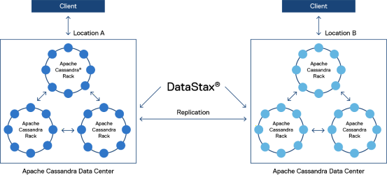
Apache Cassandra organizes data using a ring topology. When data is written to a database, Apache Cassandra creates a token that determines in which nodes the data will reside. Apache Cassandra stores data redundantly across racks and data centers to ensure data availability if nodes become unavailable.
Figure 2. Overview of a DataStax Enterprise deployment across multiple data centers; clients can connect to any node within any cluster, while DataStax Enterprise OpsCenter manages all clusters and nodes
When a user or application queries an Apache Cassandra database through client software, the client connects to any node within the cluster. The node to which the client connects then becomes the coordinator node for that query. A coordinator node interacts with other nodes to collect query results, and then it returns the result to the client.
DataStax Enterprise cluster management
DataStax provides operations management software—DataStax Enterprise OpsCenter—to manage one or more DataStax clusters. OpsCenter provides visual management, configuration, security, and monitoring capabilities to DataStax Enterprise administrators. OpsCenter features include the following:
- Lifecycle Manager (LCM)—This feature simplifies cluster deployment and gives administrators the ability to manage cluster, data center, and node configurations.
- Dashboard—The OpsCenter Dashboard provides a high-level overview of cluster health, including alerts, performance metrics, in-memory tables, and Apache Spark console viewing. The OpsCenter Dashboard can also provide a condensed view of multiple cluster dashboards.
- Security management—This feature enables administrators to define security options and role-based authentication, including user role definition, LDAP, or Kerberos authentication, Secure Sockets Layer (SSL) configuration, security logging, and configuration encryption.
- Configuration and administration—OpsCenter simplifies cluster management and administration by giving administrators the ability to manage multiple clusters, configure automatic failover of OpsCenter instances, and manage bulk operations across multiple nodes.
- DataStax Enterprise Management Services—This feature includes the following management services:
- Backup Service for backing up and restoring clusters
- NodeSync Service for validating data synchronization
- Repair Service for performing cluster repair operations
- Capacity Service for monitoring cluster performance trends and capacity planning
- Best Practice Service for scheduling best practice checks across the clusters
- Performance Service for monitoring performance metrics and providing recommendations
A DataStax agent runs on each managed node within the Apache Cassandra cluster. The DataStax agent is responsible for performing OpsCenter functions, and it is automatically installed when a new cluster is created.
For more information about DataStax Enterprise OpsCenter, see the DSE OpsCenter 6.8 User Guide.
DataStax Kubernetes Operator for Apache Cassandra
More enterprises are realizing the benefits of moving to a containerized infrastructure. Containerization helps enterprises use hardware more efficiently, enables microservices-based applications, and provides a platform that enables DevOps processes. Container platforms such as Docker help development teams package applications and all their dependencies into a single, lightweight, deployable image. Container orchestration technologies such as Kubernetes help with the configuration, provisioning, and management of containers.
The DataStax Kubernetes Operator for Apache Cassandra (Cass Operator) automates the deployment and management of DataStax Enterprise in a Kubernetes cluster. Cass Operator significantly simplifies development by enabling Apache Cassandra databases to take advantage of Kubernetes orchestration in the following ways:
- Defining services, assigning containers to servers and connecting them together
- Dynamically tracking the health of running containers, restarting failed containers and managing container life cycles
- Enabling microservices-based applications that run within any Kubernetes-enabled platform
Cass Operator supports leading Kubernetes platforms, including:
- Red Hat OpenShift
- VMware Tanzu
- Open-source Kubernetes
- Amazon Elastic Kubernetes Service (EKS)
- Google Kubernetes Engine (GKE)
- Microsoft Azure Kubernetes Service (AKS)
- Pivotal Container Service (PKS)
For more information about Cass Operator, see DataStax Kubernetes Operator for Apache Cassandra.
Solution architecture
Introduction
Dell Technologies and Intel recently created a testing environment to measure the performance of DataStax Enterprise running on Dell Technologies infrastructure. The goal of the DataStax Enterprise performance test was to determine the performance of Apache Cassandra running on both Red Hat OpenShift and VMware Tanzu in the following scenarios:
- Write-intensive—Heavy write/update patterns with 10 percent reads, 90 percent writes/updates that focus on high-capacity storage and loose service-level agreement (SLA) requirements. In this context, the SLA is the request latency.
- Read-intensive—Write once/read many patterns with 90 percent reads, 10 percent writes that focus on the 10 millisecond- to 20 millisecond-SLA range and medium throughput.
- Balanced read/write—A 50 percent read/50 percent write pattern that focuses on the 10 millisecond- to 20 millisecond-SLA range with medium throughput.
- High performance—Focuses on sub-1 millisecond SLAs and high throughput using Intel Optane persistent memory (PMem). This test was only run on the Red Hat OpenShift configuration because VMware Tanzu does not support Intel Optane PMem. Other VMware options that support Intel Optane PMem are available from VMware and Dell Technologies.
While this configuration met our test-environment needs, your specific business workloads might require a different configuration. Dell Technologies can help you with sizing assistance and server choices that meet your workload demands.
Server components
The Dell EMC PowerEdge R640 server delivers the ideal balance of density and scalability, providing a scalable computing and storage platform with an ideal mix of performance, cost, and density for most data center and database applications.
The Dell EMC PowerEdge R640 server is a two-socket, 1U server platform designed for dense scale-out data center computing and storage. Users can benefit from the flexibility of 2.5-inch or 3.5-inch drives, the performance of NVMe, and embedded intelligence to ensure optimized application performance in a secure platform. With embedded diagnostics and SupportAssist, the Dell EMC PowerEdge R640 server delivers maximum uptime in a worry-free environment.

Figure 3. Dell EMC PowerEdge R640 server
The Dell EMC PowerEdge R640 server is built on a scalable system architecture and provides the choice and flexibility to easily meet performance demands and support the multiple configurations needed to optimize for the multiple Apache Cassandra database use cases defined in this project. The Dell EMC PowerEdge R640 server allows you to:
- Simplify deployment and easily scale from 3 to 1000+ nodes
- Maximize performance with up to 10 NVMe drives and 24 DIMMs, 12 of which can be DCPMMs or NVDIMMs
- Scale compute resources with 2nd Generation Intel Xeon Scalable processors, and tailor performance based on your unique workload requirements.
While the validation and performance testing for this project was performed on the Dell EMC PowerEdge R640 server, since the time of this study, the Dell EMC PowerEdge 650 server has been released. The Dell EMC PowerEdge R650 server is an enterprise server powered by 3rd Generation Intel Xeon Scalable processors designed to optimize workload performance and data center density. It is fully compatible with this application of DataStax Enterprise and delivers even higher performance than is documented in this white paper.
Infrastructure overview
Dell Technologies and Intel engineers deployed two DataStax Enterprise configurations that mirrored a typical, yet smaller-scale, Apache Cassandra deployment. The first configuration used Red Hat OpenShift, while the second configuration used VMware Tanzu. Both of these configurations are the foundation of modern Kubernetes container environments.
Red Hat OpenShift configuration
The Red Hat OpenShift deployment consisted of five Dell EMC PowerEdge R640 servers running Red Hat OpenShift Container Platform 4.6.6. Because of the smaller test environment, there were no separate control-plane nodes. All control-plane and management containers ran on the same servers as Apache Cassandra, which allowed better resource utilization. Larger production clusters that contain additional management and monitoring components would use dedicated control-plane nodes with monitoring and logging tools.
Red Hat OpenShift was installed on Red Hat Enterprise Linux CoreOS (RHCOS), a lightweight container-based Linux operating system, with OpenShift software-defined networking (SDN). The engineers followed the Red Hat OpenShift installation procedures as described in the Red Hat OpenShift documentation.
Two additional components were used with the Red Hat OpenShift configuration:
- Local Storage Operator—This component exposed each server’s local storage devices as persistent volumes that are used by the Apache Cassandra workload.
- Keepalived and External IP—These components exposed Kubernetes services and workloads to the external network, which is necessary in deployments where additional external load balancers are not being used. These components can be installed and configured using the OperatorHub in the OpenShift Container Platform web console. The node configuration can be viewed using the following command:
# kubectl –context ocp get nodes
NAME STATUS ROLES AGE VERSION
ocp1 Ready loadbalancer,master,worker 62d v1.19.0+43983cd
ocp2 Ready loadbalancer,master,worker 62d v1.19.0+43983cd
ocp3 Ready loadbalancer,master,worker 62d v1.19.0+43983cd
ocp4 Ready loadbalancer,worker 62d v1.19.0+43983cd
ocp5 Ready loadbalancer,worker 62d v1.19.0+43983cd
- DataStax Kubernetes Operator for Apache Cassandra—This component was used to ease Apache Cassandra database deployment and life cycle management.
Apache Cassandra is responsible for data redundancy and replication, so there is no need for a storage solution that provides these functions. This capability helps reduce costs and complexity, and it can also scale with the number of Apache Cassandra nodes. Enterprises can use standard Linux Logical Volume Manager (LVM) commands to create smaller logical volumes for each physical server, or they can combine multiple storage devices into a large volume. For this test, each server contained a single volume on each storage device.
Each server was running multiple Apache Cassandra instances to allow better resource utilization and data redundancy. Each server was assigned to a separate logical Apache Cassandra rack, which helps ensure that multiple copies of the same data never reside on the same physical server. With a replication factor of 3 (RF=3), the deployment contained 15 pods running Apache Cassandra database instances. Each pod was assigned 16 logical CPUs and 48 GB of RAM. The pod configuration can be viewed using the following command:
# kubectl –context ocp get pods
NAME READY STATUS RESTARTS AGE
cass-operator-6b76b647ff-6sb7h 1/1 Running 0 9d
cluster1-dc1-racka-sts-0 2/2 Running 0 2d20h
cluster1-dc1-racka-sts-1 2/2 Running 0 2d20h
cluster1-dc1-racka-sts-2 2/2 Running 0 2d20h
cluster1-dc1-rackb-sts-0 2/2 Running 0 2d20h
cluster1-dc1-rackb-sts-1 2/2 Running 0 2d20h
cluster1-dc1-rackb-sts-2 2/2 Running 0 2d20h
cluster1-dc1-rackc-sts-0 2/2 Running 0 2d20h
cluster1-dc1-rackc-sts-1 2/2 Running 0 2d20h
cluster1-dc1-rackc-sts-2 2/2 Running 0 2d20h
cluster1-dc1-rackd-sts-0 2/2 Running 0 2d19h
cluster1-dc1-rackd-sts-1 2/2 Running 0 2d19h
cluster1-dc1-rackd-sts-2 2/2 Running 0 2d20h
cluster1-dc1-racke-sts-0 2/2 Running 0 2d19h
cluster1-dc1-racke-sts-1 2/2 Running 0 2d19h
cluster1-dc1-racke-sts-2 2/2 Running 0 2d19h
Red Hat OpenShift server configuration
The storage configuration for each of the five servers varied among the write-intensive, read-intensive, balanced read/write, and high-performance scenarios. The Red Hat OpenShift write-intensive scenario used the Dell EMC PowerEdge R640 server configuration, as shown in the following table:
Table 1. Dell EMC PowerEdge R640 configuration for Red Hat OpenShift write-intensive scenario
|
Component |
Description |
|
CPU |
Two Intel Xeon Gold 6248 processors running at 2.5 GHz |
|
Memory |
Twelve 32 GB RDIMM DDR4 memory modules running at 2,666 MHz, for a total of 384 GB |
|
Storage controller |
Dell EMC HBA330 12 Gbps) Serial-Attached SCSI (SAS) host-bus adapter (HBA) controller in a non-RAID configuration |
|
Boot device |
480 GB Dell EMC Boot-Optimized Server Storage (BOSS)-S1 boot device |
|
Storage |
Eight 1.92 TB Intel Solid State Drive (SSD) D3-S4510 2.5-inch Serial ATA (SATA) drives; for write-intensive workloads, Intel recommends the higher endurance Intel SSD D3-S4610. |
|
Embedded network interface controller (NIC) 1 |
Dual-port 10 GbE Intel Ethernet Converged Network Adapter X710 SFP+ |
|
Embedded NIC 2 |
Dual-port 1 GbE Intel Ethernet Server Adapter i350 |
|
Additional NIC |
Dual-port 100 GbE Intel Ethernet Network Adapter E810-CQDA2 PCIe |
The Red Hat OpenShift read-intensive and balanced read/write scenarios used the Dell EMC PowerEdge R640 server configuration, as shown in the following table:
Table 2. Dell EMC PowerEdge R640 configuration for the Red Hat OpenShift read-intensive scenario
|
Component |
Description |
|
CPU |
Two Intel Xeon Gold 6248 processors running at 2.5 GHz |
|
Memory |
Twelve 32 GB RDIMM DDR4 memory modules running at 2,666 MHz, for a total of 384 GB |
|
Storage controller |
Dell HBA330 12 Gbps SAS HBA controller in a non-RAID configuration |
|
Boot device |
480 GB Dell BOSS-S1 boot device |
|
Storage |
Four 1.6 TB Intel SSD DC P4610 2.5-inch NVM Express (NVMe) SSDs |
|
Embedded NIC 1 |
Dual-port 10 GbE Intel Ethernet Converged Network Adapter X710 SFP+ |
|
Embedded NIC 2 |
Dual-port 1 GbE Intel Ethernet Server Adapter i350 |
|
Additional NIC |
Dual-port 100 GbE Intel Ethernet Network Adapter E810-CQDA2 PCIe |
The Red Hat OpenShift high-performance scenario used the Dell EMC PowerEdge R640 server configuration, as shown in the following table:
Table 3. Dell EMC PowerEdge R640 configuration for Red Hat OpenShift performance scenario
|
Component |
Description |
|
CPU |
Two Intel Xeon Platinum 8280L processors running at 2.7 GHz |
|
Memory |
Twelve 32 GB RDIMM DDR4 memory modules running at 2,666 MHz, for a total of 384 GB |
|
Persistent memory |
Twelve 512 GB Intel Optane PMem modules, for a total of 6 TB, configured for Block (BLK) mode. |
|
Storage controller |
Dell HBA330 12 Gbps SAS HBA controller in a non-RAID configuration |
|
Boot device |
480 GB Dell BOSS-S1 boot device |
|
Embedded NIC 1 |
Dual-port 10 GbE Intel Ethernet Converged Network Adapter X710 SFP+ |
|
Embedded NIC 2 |
Dual-port 1 GbE Intel Ethernet Server Adapter i350 |
|
Additional NIC |
Dual-port 100 GbE Intel Ethernet Network Adapter E810-CQDA2 PCIe |
VMware Tanzu configuration
The VMware Tanzu configuration consisted of five Dell EMC PowerEdge R640 servers running VMware vSphere 7.0 Update 1 with Tanzu. The VMware vCenter Server VM that is used to manage the VMware vSphere cluster was deployed on an additional, separate Dell EMC PowerEdge R640 server. While it is possible to run VMware vCenter on the same VMware vSphere cluster that it manages, VMware recommends running the VMware vCenter VM on a separate management cluster. The engineers followed the installation procedures provided in VMware documentation.
The VMware vSphere cluster was configured with the following:
- Security patches—The latest security patches were applied after the cluster was configured.
- Storage configuration—The five servers were configured with VMware vSAN, which provided high-performance, redundant storage for both VMware vSphere VMs and Tanzu Kubernetes workloads, including Apache Cassandra. The vSAN storage included a cache tier configured using Intel Optane SSDs, in addition to a capacity tier configured using NAND-based SSDs.
- Networking—The VMware vSphere cluster used the vSphere Distributed vSwitch for networking.
When VMware vSphere was fully configured, the engineers installed and configured VMware Tanzu with the following settings:
- Networking—We created port groups and installed the HAProxy virtual application as a load balancer for VMware Tanzu API servers and workload services. This configuration is the only supported load-balancing solution unless the VMware vSphere cluster is using VMware NSX-T Data Center for networking. The Kubernetes worker cluster was deployed using Kubernetes version 1.18.5 and Antrea Container Network Interface (CNI) network. Organizations can also use VMware NSX-T Data Center as a CNI provider.
- Content libraries—The content libraries contained the VMware Tanzu images.
- Supervisor Cluster—We deployed the VMware Tanzu Supervisor Cluster using the tiny deployment size because only a single Kubernetes cluster was running. In a production environment, organizations can install multiple separate Kubernetes clusters on the same physical VMware vSphere infrastructure because VMware Tanzu Kubernetes workers run on their own VMs.
- Kubernetes—The engineers created a single workload namespace with access to all available cluster resources. They deployed a single Kubernetes workload cluster using three control-plane nodes and 10 worker nodes. Because there is no predefined node size, they used the best-effort-8xlarge VM class type for the worker nodes, with each node configured with 32 vCPUs and 128 GB of RAM. The control-plane nodes used the best-effort-xsmall VM class type, with each node configured with 2 vCPUs and 2 GB of RAM. For more information about VMware Tanzu VM class types, see Virtual Machine Class Types for Tanzu Kubernetes Clusters.
- DataStax Kubernetes Operator for Apache Cassandra—This component was used to ease Apache Cassandra database deployment and life cycle management.
When VMware Tanzu is deployed, the node configuration can be viewed using the following command:
# kubectl --context tkg get nodes NAME STATUS ROLES AGE VERSION tkg-control-plane-967f5 Ready master 10d v1.18.5+vmware.1 tkg-control-plane-n2x96 Ready master 10d v1.18.5+vmware.1 tkg-control-plane-pvsnl Ready master 10d v1.18.5+vmware.1 tkg-workers-zqq6s-847b88dd66-4l6s5 Ready <none> 10d v1.18.5+vmware.1 tkg-workers-zqq6s-847b88dd66-5kz5w Ready <none> 10d v1.18.5+vmware.1 tkg-workers-zqq6s-847b88dd66-5p4wk Ready <none> 10d v1.18.5+vmware.1 tkg-workers-zqq6s-847b88dd66-6z67r Ready <none> 10d v1.18.5+vmware.1 tkg-workers-zqq6s-847b88dd66-9dhxl Ready <none> 10d v1.18.5+vmware.1 tkg-workers-zqq6s-847b88dd66-fbntb Ready <none> 10d v1.18.5+vmware.1 tkg-workers-zqq6s-847b88dd66-fc5dx Ready <none> 10d v1.18.5+vmware.1 tkg-workers-zqq6s-847b88dd66-g2tmg Ready <none> 10d v1.18.5+vmware.1 tkg-workers-zqq6s-847b88dd66-gqj2n Ready <none> 10d v1.18.5+vmware.1 tkg-workers-zqq6s-847b88dd66-qcwrq Ready <none> 10d v1.18.5+vmware.1
With 10 virtual Kubernetes workers running on five physical server nodes, the engineers created nine Apache Cassandra node instances and grouped them into three logical racks using a replication factor of 3 (RF-3). Each Apache Cassandra pod was running on a separate worker node, with each pod assigned 16 logical CPUs and 64 GB of RAM. The physical servers had Intel Hyper-Threading Technology (Intel HT Technology) enabled, so the 32 CPUs assigned to each worker node were logical cores, not physical cores. Unfortunately, there is some discrepancy in how VMware vSphere and VMware Tanzu count CPU cores with Intel HT Technology enabled, so organizations must consider this discrepancy when planning their own deployments. For more information about this discrepancy, see “vSphere 7 with Kubernetes” in Performance Best Practices for VMware vSphere 7.0.
The pod configuration can be viewed using the following command:
# kubectl --context tkg get pods
NAME READY STATUS RESTARTS AGE
cass-operator-557f6689df-527mq 1/1 Running 0 9d
cluster2-dc1-rack1-sts-0 2/2 Running 0 2d20h
cluster2-dc1-rack1-sts-1 2/2 Running 0 2d20h
cluster2-dc1-rack1-sts-2 2/2 Running 0 2d20h
cluster2-dc1-rack2-sts-0 2/2 Running 0 2d20h
cluster2-dc1-rack2-sts-1 2/2 Running 0 2d20h
cluster2-dc1-rack2-sts-2 2/2 Running 0 2d20h
cluster2-dc1-rack3-sts-0 2/2 Running 0 2d20h
cluster2-dc1-rack3-sts-1 2/2 Running 0 2d20h
cluster2-dc1-rack3-sts-2 2/2 Running 0 2d20h
VMware Tanzu server configuration
The storage configuration for each of the five servers varied among the write-intensive, read-intensive, balanced read/write, and high-performance scenarios. The VMware Tanzu write-intensive scenario used the Dell EMC PowerEdge R640 server configuration, as shown in the following table:
Table 4. Dell EMC PowerEdge R640 server configuration for the VMware Tanzu write-intensive scenario
|
Component |
Description |
|
CPU |
Two Intel Xeon Gold 6248 processors running at 2.5 GHz |
|
Memory |
Twelve 32 GB RDIMM DDR4 memory modules running at 2,666 MHz, for a total of 384 GB |
|
Storage controller |
Dell HBA330 12 Gbps SAS HBA controller in a non-RAID configuration |
|
Boot device |
480 GB Dell BOSS-S1 boot device |
|
SSD storage |
Eight 1.92 TB Intel SSD D3-S4510 2.5-inch SATA drives. For write-intensive workloads, Intel recommends the higher endurance Intel SSD D3-S4610. |
|
NVMe SSD storage |
Two Intel Optane SSD DC P4800X NVMe drives |
|
Embedded NIC 1 |
Dual-port 10 GbE Intel Ethernet Converged Network Adapter X710 SFP+ |
|
Embedded NIC 2 |
Dual-port 1 GbE Intel Ethernet Server Adapter i350 |
|
Additional NIC |
Dual-port 100 GbE Intel Ethernet Network Adapter E810-CQDA2 PCIe |
The VMware Tanzu read-intensive and balanced read/write scenarios used the Dell EMC PowerEdge R640 server configuration, as shown in the following table:
Table 5. Dell EMC PowerEdge R640 server configuration for the VMware Tanzu read-intensive and balanced read/write scenarios
Because VMware Tanzu does not support Intel Optane PMem, the high-performance scenario was not run on VMware Tanzu.
Testing methodology
When the various testing environments were created and configured, Dell Technologies and Intel engineers ran a series of performance tests specific to Apache Cassandra. A closed-loop tuning approach was used where only one parameter was varied for any given test. This methodology isolates the effect of any one configuration change and is more deterministic than making several tuning changes in parallel.
The performance tests used the cassandra-stress tool, a Java-based utility for benchmarking and load testing Apache Cassandra. The tool is used to measure the Apache Cassandra cluster’s total throughput by adding all the client operations per second. The engineers also measured the SLA, which is the average latency required to achieve maximum throughput. The SLA for these scenarios is the average of all client operations per second throughput at 99th percentile latency. The engineers can vary the number of client threads until the clients achieve throughput at or below the target SLA. For more information about cassandra-stress, see the DSE 6.8 Developer Guide.
The engineers ran each performance benchmark for 10 minutes each. To provide predictable performance results, the dataset was compacted after each run and the caches were cleared before starting the next benchmark.
Client configuration
The Dell Technologies and Intel engineers ran all performance tests from three separate client machines. Overall, this configuration represents a typical hybrid or multicloud deployment where applications or clients that use the Apache Cassandra run from a remote location.
For specific information about the Apache Cassandra settings, database build commands and benchmark steps, see Appendix A.
Performance results
Introduction
The following sections discuss the performance results.
Red Hat OpenShift and VMware Tanzu configuration with SATA SSDs
Figure 3 displays the combined results of the DataStax Enterprise benchmark tests for the read-intensive, write-intensive, and balanced read/write scenarios on the Red Hat OpenShift cluster, while Figure 4 displays the same results for the VMware Tanzu cluster running on SATA SSDs. The x-axis displays the total throughput in operations per second performed during each test’s 10-minute run, while the y-axis displays the mean latency in milliseconds for each operation during the run.
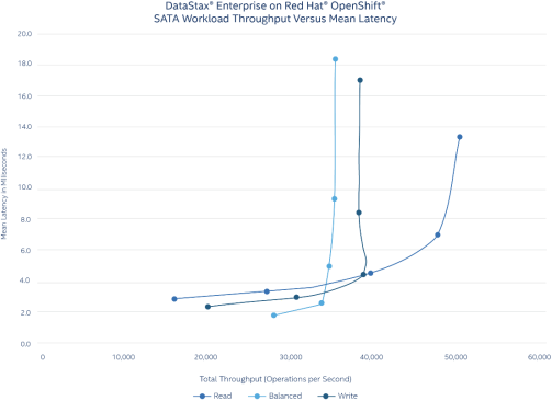
Figure 3. SATA SSD benchmark results for the DataStax Enterprise read-intensive, balanced read/write, and write-intensive scenarios on the Red Hat OpenShift cluster
The Red Hat OpenShift cluster test consisted of five test runs for each read-intensive, write-intensive, and balanced read/write scenario. Each data point on the chart represents a test run with a specific number of client threads that simulate client loads. The number of client threads for each test run were:
- First test run: 40 client threads
- Second test run: 80 client threads
- Third test run: 160 client threads
- Fourth test run: 320 client threads
- Fifth test run: 640 client threads
Figure 3 shows that latency moderately increased for the 90 percent read/10 percent write scenario, while the latency dramatically increased during the mixed 50 percent read/50 percent write (balanced read/write) and 10 percent read/90 percent write scenarios as the number of client threads increased. The maximum operations per second occurred with the 90 percent read/10 percent write workload at 49,433 with 640 client threads.
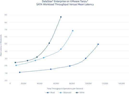
Figure 4. SATA SSD benchmark results for the DataStax Enterprise read-intensive, balanced read/write, and write-intensive scenarios on the VMware Tanzu cluster
The VMware Tanzu cluster test consisted of five test runs for each read-intensive, write-intensive, and balanced read/write scenarios. As with the Red Hat OpenShift tests, each data point on the chart represents a test run with a specific number of client threads that simulate client loads. The number of client threads for each test run were:
- First test run: 18 client threads
- Second test run: 72 client threads
- Third test run: 144 client threads
- Fourth test run: 288 client threads
- Fifth test run: 576 client threads
Figure 4 shows latency moderately increased during the mixed 50 percent read/50 percent write (balanced read/write) and 10 percent read/90 write scenarios, while the latency increase was slightly higher during the 90 percent read/10 percent write scenario. The maximum operations per second occurred with the 10 percent read/90 percent write workload at 115,817 with 576 client threads.
Red Hat OpenShift and VMware Tanzu configuration with NVMe
Figure 5 displays the combined results of the DataStax Enterprise benchmark tests for the read-intensive, write-intensive, and balanced read/write scenarios on the Red Hat OpenShift cluster, while Figure 6 displays the same results for the VMware Tanzu cluster running on NVMe. The x-axis displays the total throughput in operations per second performed during each test’s 10-minute run, while the y-axis displays the mean latency in milliseconds for each operation during the run.
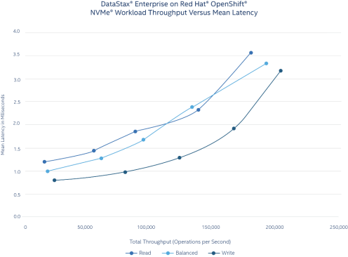
Figure 5. NVMe benchmark results for the DataStax Enterprise read-intensive, balanced read/write, and write-intensive scenarios on the Red Hat OpenShift cluster
The Red Hat OpenShift cluster test consisted of five test runs for each read-intensive, write-intensive, and balanced read/write scenarios. Each data point on the chart represents a test run with a specific number of client threads that simulate client loads. The number of client threads for each test run were:
- First test run: 20 client threads
- Second test run: 80 client threads
- Third test run: 160 client threads
- Fourth test run: 320 client threads
- Fifth test run: 640 client threads
Figure 5 shows that latency moderately increased for the 90 percent read/10 percent write, mixed 50 percent read/50 percent write (balanced read/write), and 10 percent read/90 percent write scenarios as the number of client threads increased. The maximum operations per second occurred with the 90 percent read/10 percent write workload at 201,797 with 640 client threads.
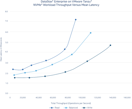
Figure 6. NVMe benchmark results for the DataStax Enterprise read-intensive, balanced read/write, and write-intensive scenarios on the VMware Tanzu cluster
The VMware Tanzu cluster test consisted of six test runs for each read-intensive, write-intensive, and balanced read/write scenarios. Each data point on the chart represents a test run with a specific number of client threads that simulate client loads. The number of client threads for each test run were:
- First test run: 10 client threads
- Second test run: 40 client threads
- Third test run: 80 client threads
- Fourth test run: 160 client threads
- Fifth test run: 320 client threads
- Sixth test run: 640 client threads
Figure 6 shows that latency significantly increased for the 90 percent read/10 percent write scenario at 320 client threads, while latency moderately increased for the mixed 50 percent read/50 percent write (balanced read/write) and 10 percent read/90 percent write scenarios as the number of client threads increased. The maximum operations per second occurred with the 90 percent read/10 percent write workload at 135,815 with 640 client threads.
Red Hat OpenShift configuration with Intel Optane persistent memory
Figure 7 shows the combined results of the DataStax Enterprise benchmark tests for the read-intensive, write-intensive, and balanced read/write scenarios on the Red Hat OpenShift cluster configured with Intel Optane PMem. The x-axis displays the total throughput in operations per second performed during each test’s 10-minute run, while the y-axis displays the mean latency in milliseconds for each operation during the run.
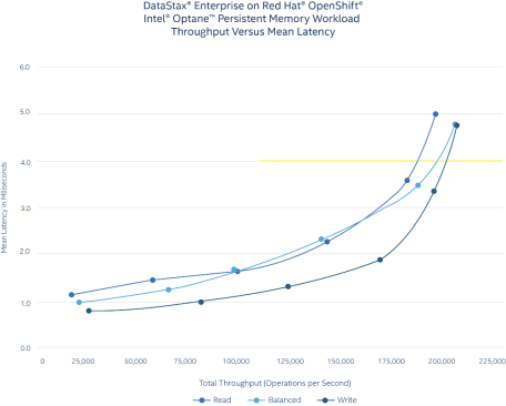
Figure 7. Benchmark results for the DataStax Enterprise read-intensive, balanced read/write, and write-intensive scenarios on the Red Hat OpenShift cluster configured with Intel Optane persistent memory
The Red Hat OpenShift cluster test consisted of six test runs for each read-intensive, write-intensive, and balanced read/write scenarios. Each data point on the chart represents a test run with a specific number of client threads that simulate client loads. The number of client threads for each test run were:
- First test run: 20 client threads
- Second test run: 80 client threads
- Third test run: 160 client threads
- Fourth test run: 320 client threads
- Fifth test run: 640 client threads
- Sixth test run: 960 client threads
Figure 7 shows that latency moderately increased for both the 90 percent read/10 percent write scenario and the mixed 50 percent read/50 percent write scenario. The latency showed a more dramatic increase in test four in the 10 percent read/90 write scenario. The maximum operations per second occurred with the 10 percent read/90 percent write workload at 203,099 with 960 client threads.
Summary
Conclusion
As enterprises explore how to better make use of legacy applications, DataStax Enterprise can give them the ability to use new datatypes and provide a data foundation for application modernization. Built on Apache Cassandra, DataStax Enterprise can scale from small deployments with a handful of nodes to large deployments that span across data centers.
The benchmark tests in this paper were performed in a test environment built with Dell EMC PowerEdge servers, in addition to DataStax, Red Hat, and VMware software. The benchmark results show that DataStax Enterprise performs well in a Kubernetes environment using either Red Hat OpenShift or VMware Tanzu running on Dell EMC PowerEdge servers. While our test configuration met the needs for running our performance tests, your business workloads might require different configurations and deployment models. Dell Technologies can help you with sizing assistance, server choices, and software licensing that meet your specific business requirements.
For more information about how Dell Technologies can help with your application modernization initiatives, contact your Dell Technologies representative.
Resources
Additional information
The following Dell Technologies and DataStax documentation provides additional and relevant information. Access to these documents depends on your login credentials. If you do not have access to a document, contact your Dell Technologies representative.
Appendix A
Apache Cassandra configuration settings
The following table provides Apache Cassandra configuration settings, database build commands, and stress test commands:
Table 6. Apache Cassandra settings
|
Component |
Description |
|
Number of physical servers |
5 |
|
Replication factor (RF) |
3 (default) |
|
Read consistency level |
Local quorum |
|
Write consistency level |
Local quorum |
|
Compression type |
LZ4 (default) |
|
Compression chunk size |
64 KB (default) |
|
Cassandra Query Language (CQL) schema |
Schema built with cqlstress-insanity-example.yaml. This schema is approximately 1.1 KB per partition uncompressed, and approximately 700 bytes compressed. |
|
Compaction type |
LeveledCompactionStrategy |
|
Total number of database entries |
2 billion entries for the cqlstress-insanity-example.yaml schema, which requires approximately 3.5 TB of disk space for one copy of the database on the cluster. With an RF of 3, the total database size is approximately 10.5 TB. |
|
Java version |
Latest Java 1.8 version supported by the operating system |
|
Benchmark tool |
cassandra-stress |
|
Storage device file system |
XFS |
|
Benchmark workloads |
|
|
SLA |
Median value of all three clients at 99th percentile latency of 10 milliseconds |
|
Key metric |
Total operations per second and median SLA for all clients |
|
Test time |
10 minutes per run |
|
Kubernetes yaml configuration file settings |
Other production-level settings
Apply the system and Apache Cassandra settings as found in Recommended production settings.
Steps for building and saving the test database
Perform the following steps to build and save the test database:
- Run the following command from the client system to build the database:
<CASSANDRA_HOME_DIR>/tools/bin/cassandra-stress user profile=<CASSANDRA_HOME_DIR>/tools/cqlstress-insanity-example.yaml ops\(insert=1\) no-warmup cl=THREE n=total_number_entries -mode native cql3 –pop seq=1..total_number_entries -node <node_IP_address> -rate threads=<number_of_client_threads>
- To accelerate compaction and not limit it, modify the default Cassandra throughput temporarily using the following command:
<CASSANDRA_HOME_DIR>/bin/nodetool setcompactionthroughput 0
- After the initial table has been created, wait for all compaction processes to complete before stopping Apache Cassandra:
- Flush Cassandra memory buffers using the following command:
<CASSANDRA_HOME_DIR>/bin/nodetool flush
- Wait until all compaction jobs are done using the following command:
<CASSANDRA_HOME_DIR>/bin/nodetool compactionstats
- When the compaction is completed, you can restore the compaction throughput to default:
<CASSANDRA_HOME_DIR>/bin/nodetool setcompactionthroughput 16
Run the Apache Cassandra benchmarks
Perform the following steps to run the Apache Cassandra benchmarks:
- Run the following command to benchmark the random 90 percent reads/10 percent writes:
<CASSANDRA_HOME_DIR>/tools/bin/cassandra-stress user profiile=<CASSANDRA_HOME_DIR>/tools/cqlstress-insanity-example.yaml ops\(insert=10,simple1=90\) cl=ONE duration=10m -mode native cql3 –pop dist=uniform\(1.. total_number_entries >\) -node <node_IP_address> -rate threads=<number_of_client_threads>
Rate threads are adjusted to a value that gives the maximum throughput for a given SLA.
- Run the following command to benchmark the random 10 percent reads/90 percent writes:
<CASSANDRA_HOME_DIR>/tools/bin/cassandra-stress user profile=<CASSANDRA_HOME_DIR>/tools/cqlstress-insanity-example.yaml ops\(insert=90,simple1=10\) cl=ONE duration=10m -mode native cql3 –pop dist=uniform\(1.. total_number_entries \) -node <node_IP_address> -rate threads=<number_of_client_threads>
Rate threads are adjusted to a value that gives the maximum throughput for a given SLA.
- Run the following command to benchmark the random mix of 50 percent reads/50 percent writes (50 percent read, 50 percent write):
<CASSANDRA_HOME_DIR>/tools/bin/cassandra-stress user profile=<CASSANDRA_HOME_DIR>/tools/cqlstress-insanity-example.yaml ops\(insert=50,simple1=50\) cl=ONE duration=10m -mode native cql3 –pop dist=uniform\(1.. total_number_entries \) -node <node_IP_address> -rate threads=<number_of_client_threads>