Implementation Guide—Oracle Database 19c Best Practices on PowerStore
Introduction
Solution introduction
Architecture concepts and requirements
Architecture design
Architecture design includes various aspects of the solution such as components of physical layer, software layer, and storage volumes design. The architecture was designed to broadly represent the infrastructure that customers use for their Oracle databases. Two nodes of Dell PowerEdge R750xs servers were used for the compute layer, and a single PowerStore 5000T was used for storage needs.
This two-node architecture is built to provide a high availability design. It can be extended to three or more nodes to consolidate more databases.
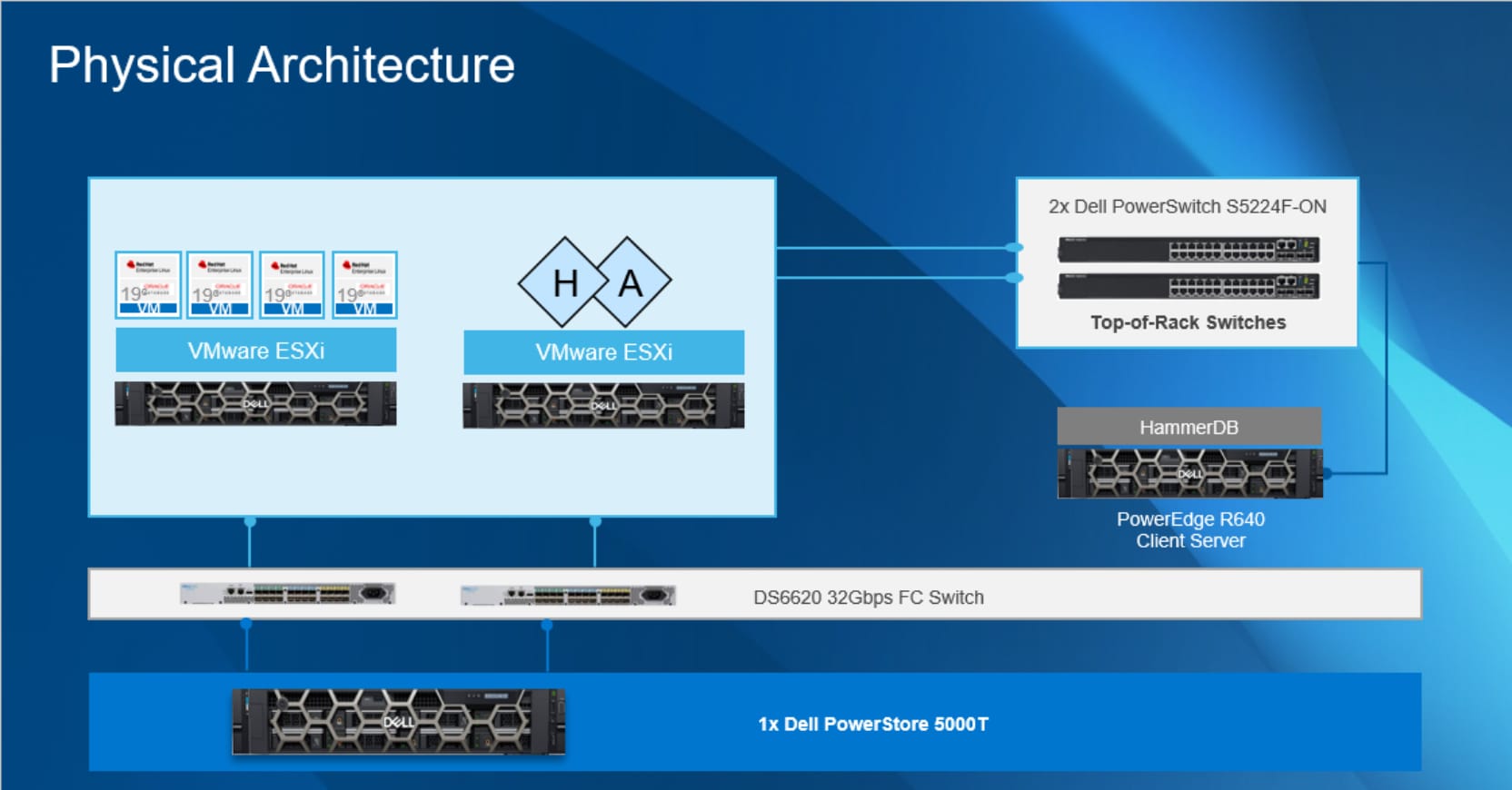
Figure 1: Architecture design
The server layer consists of database ESXi servers and two R750xs PowerEdge servers running ESXi 7.3 hypervisors for four VMs running Red Hat Enterprise Linux 8.5 guest operating system. Only one of the two servers is actively used for benchmarking and the second server is reserved for high availability.
Each ESXi server consists of:
- Two 25 GbE network interface cards (NICs): Two dual-port 25 GbE network interface controllers for Oracle public and vMotion
- Two 32 Gbps host bus adapters (HBAs): Two dual-port 32 Gbps HBAs for SAN traffic in database servers
- One GbE management rNDC: At least one 1 GbE rNDC or LOM port for in-band management of the server from within the operating system
- One GbE integrated Dell Remote Access Controller (iDRAC): A dedicated iDRAC Ethernet port for out-of-band (OOB) management of servers
- R640 management/tool server: The R640 server runs VMware ESXi 7.3 as the hypervisor to host multiple VMs, as follows:
- VMware vCenter Server Appliance (VCSA) deployed as a VM
- VM with Red Hat Enterprise Linux 8.5 guest operating system installed to run the HammerDB test tool
The network layer consists of the following types of connectivity:
- Management network between vCenter and ESXi hosts. This network also connects the iDRAC Ethernet ports of all the servers
- vMotion network for VM migration using vMotion between ESXi hosts
- Public network that connects the database server and the Oracle database instance to with the rest of the data center network
- SAN FC network that connects database servers and PowerStore SAN storage
The networks are implemented with the following switches:
- One 1 GbE switch for management switches
- Two 25 GbE ToR switches for the Oracle public and vMotion network
- Two 32 Gbps FC switches for FC SAN connectivity
The storage layer consists of the PowerStore T array as the FC SAN storage for databases and the data stores for VM operating system volumes.
Hardware components
Software components
Storage volume design
Baseline configuration details
Baseline configuration
ESXi system configuration
Use the following steps to configure the physical servers that host the database VMs:
- Use the BIOS settings for the PowerEdge servers described in 0.
- Create a single virtual disk in a RAID 1 configuration with two local disks (SSDs or HDDs) per server to install the bare-metal operating system (ESXi 7.3).
- Install ESXi 7.3 by using the Dell customized ISO image.
- Configure, monitor, and maintain the ESXi host, virtual networking, and the VM by using the VMware vSphere web client and VCSA, which is deployed as a VM on the management server.
- Zone two dual-port 32 Gb/s HBAs (four initiators in total) and configure these HBAs with the PowerStore front-end Fibre Channel ports for high bandwidth, load-balanced, and highly available SAN traffic.
PowerStore storage configuration details
The PowerStore volume group feature enables the administrator to create a configuration that facilitates ease of management, efficient snapshots, and replication. This section explains the design principles used to create volumes. For the baseline storage configuration, all four virtualized databases (DB1 to DB4) used the same design. The following table shows the baseline storage configuration for DB1. The database used was named ORABP22:
Table 8: PowerStore storage volumes
|
Volume Group |
Volume Name |
Number of LUNs |
VMware Datastore |
Volume size (GB) |
Notes |
|
orabp22-vm1-os |
orabp22-vm1-os |
1 |
orabp22-vm1-os-ds |
400 |
Operating System |
|
orabp22-vm1-grid |
orabp22-vm1-grid-001 |
1 |
orabp22-vm1-grid-001-ds |
50 |
GRID |
|
orabp22-vm1-grid-002 |
1 |
orabp22-vm1-grid-002-ds |
50 |
||
|
orabp22-vm1-grid-003 |
1 |
orabp22-vm1-grid-003-ds |
50 |
||
|
orabp22-vm1-db1 |
orabp22-vm1-db1-data-001 |
1 |
orabp22-vm1-data-001-ds |
1000 |
Data files |
|
orabp22-vm1-db1-redo-001 |
1 |
orabp22-vm1-redo-001-ds |
55 |
Online redo logs |
|
|
orabp22-vm1-db1-fra-001 |
1 |
orabp22-vm1-fra-001-ds |
60 |
Flash Recovery Area |
|
|
orabp22-vm1-temp |
orabp22-vm1-db1-temp |
1 |
orabp22-vm1-temp-ds |
500 |
Temp files |
The naming convention using VMn and DBn allowed the database administrators to increment the value to create volume groups for other databases. For example, the second copy of the database had a volume group name of ORABP22_VM2_DB2. Using this naming convention allowed the administration team to repurpose copies of the database quickly. Each LUN was configured as a VMware datastore. For detailed PowerStore best practices and features, see Storage Best Practices.
SAN FC network zoning configuration
Each ESXi host (R750xs server) has two dual-port Fibre Channel HBAs. The PowerStore 5000T under test has two Fibre Channel front-end I/O modules (one per node). Each I/O module has four 32Gbps ports with a total of eight 32Gbps front-end ports. There are two Connectrix Fibre Channel switches. Each Connectrix switch is its own fabric. For connectivity, each ESXi host was zoned to all eight front-end ports of the PowerStore across the two switches. This configuration should be the default setup. This configuration ensures high availability against a single component failure of the stack. Figure 2 shows the SAN zoning configuration.
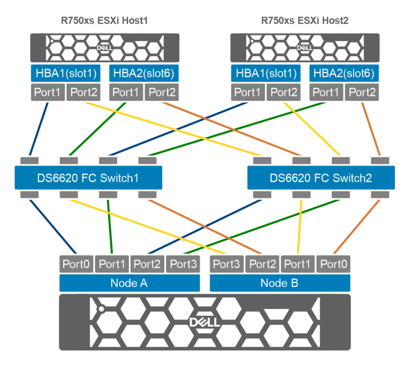
Figure 2: Baseline SAN FC connectivity and zoning
VM network: Distributed Network switches
We configured the following two distributed network switches: ESXI-Mgmt DS ESXi server management that connects to the vCenter and ESXi hosts and OraPub-vMotion that supports the VM network for Oracle database public network and vMotion.
Table 9 describes the details of these two distributed network switches.
Table 9: Distributed network switches
|
Distributed network switches |
Uplink ports |
Purpose |
VM port group |
|
ESXI-Mgmt DS |
On 2x 1GB network (rNDC) vmnic0 and vmnic 1 |
ESXi server host management |
|
|
OraPub-vMotion |
2x25 GbE physical network: vmnic5 and vmnic11 |
Oracle Database public network and vMotion network |
OraPub |
Table 10: VMware Network settings
|
Network Settings |
Jumbo Frames |
Disabled |
|
VMXNET3 adapter |
Yes |
Server physical NIC port, HBA port, and switch connectivity
Table 11 shows the physical NIC ports, their associated switches, and port groups. The last two columns, SAN FC A and SAN FC B, are the two dual port HBAs that are connected to the Fibre channel switches. The last row describes the switch ports that are connected the corresponding NICs ports or the HBA ports.
Table 11: Switches ports, NIC ports and HBA ports in Ethernet network and SAN FC network
|
Server |
ESXi Mgmt Network |
Oracle Pub Group |
vMotion Network |
SAN FC A |
SAN FC B |
|
R750xs-92P-18 |
vmnic0(e:1), vmnic1(e:2) |
vmnic2(i:1) |
vmnic4(2:1) |
1:1, 6:1 |
1:2, 6:2 |
|
R750xs-92P-20 |
vmnic0(e:1), vmnic1(e:2) |
vmnic2(i:1) |
vmnic4(2:1) |
1:1, 6:1 |
1:2, 6:2 |
|
Switch Ports |
L42K-92O-SW1:10 On L45K-98Q-SW01 Fex 132 (ACCESS VLAN 379) |
S5224-92O-40:11 (TRUNK VLAN 382, 99) |
S5224-92O-40:11 (TRUNK VLAN 382, 99) |
DS6620-92J:1:8 |
DS6620-92J:2:8 |
Figure 3 describes the configuration of the physical and virtual network and the SAN Fibre Channel Network. In the middle of the figure, two virtually distributed switches established the mapping of the virtual network port groups and physical uplinks:
Distributed switch vDS-01-ESXi-Mgmt connects the port group ESXi-Mgmt-3780dPG and the two physical uplinks vmnic0 and vmnic1.
Distributed switch vDS-02-Orapub-Vmotion connects two port groups: pub-25GbE-vlan382-dPG (for VM public network) and vMotion-25GBE-vlan99-dPG (for Motion) with two physical uplinks vmic2 and vmnic4.
The right side of the figure shows how these physical links are mapped to the physical NIC ports of each server and how these NICs ports are connected to the 25GBE TOR physical switches that connect to outside network.
The lower right side of the figure shows how the two dual ports. The HBAs are connected to the ports of two FC switches.
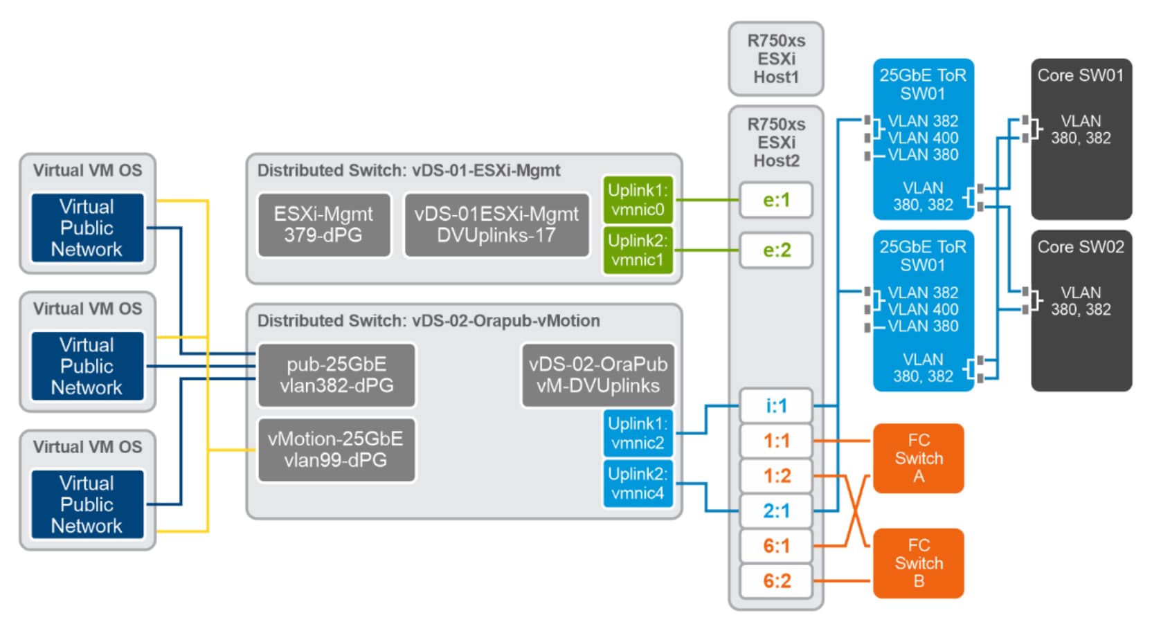
Figure 3: Physical and virtual network design
System installation and configuration
ESXi system configuration
Use the following steps to configure the physical servers that host the database VMs:
- Use the BIOS settings for the PowerEdge servers described in 0.
- Create a single virtual disk in a RAID 1 configuration with two local disks (SSDs or HDDs) per server to install the bare-metal operating system (ESXi 7.3).
- Install ESXi 7.3 by using the Dell customized ISO image.
- Configure, monitor, and maintain the ESXi host, virtual networking, and the VM by using the VMware vSphere web client and VCSA, which is deployed as a VM on the management server.
- Zone two dual-port 32 Gb/s HBAs (four initiators in total) and configure these HBAs with the PowerStore front-end Fibre Channel ports for high bandwidth, load-balanced, and highly available SAN traffic.
PowerStore storage configuration details
The PowerStore volume group feature enables the administrator to create a configuration that facilitates ease of management, efficient snapshots, and replication. This section explains the design principles used to create volumes. For the baseline storage configuration, all four virtualized databases (DB1 to DB4) used the same design. The following table shows the baseline storage configuration for DB1. The database used was named ORABP22:
Table 8: PowerStore storage volumes
|
Volume Group |
Volume Name |
Number of LUNs |
VMware Datastore |
Volume size (GB) |
Notes |
|
orabp22-vm1-os |
orabp22-vm1-os |
1 |
orabp22-vm1-os-ds |
400 |
Operating System |
|
orabp22-vm1-grid |
orabp22-vm1-grid-001 |
1 |
orabp22-vm1-grid-001-ds |
50 |
GRID |
|
orabp22-vm1-grid-002 |
1 |
orabp22-vm1-grid-002-ds |
50 |
||
|
orabp22-vm1-grid-003 |
1 |
orabp22-vm1-grid-003-ds |
50 |
||
|
orabp22-vm1-db1 |
orabp22-vm1-db1-data-001 |
1 |
orabp22-vm1-data-001-ds |
1000 |
Data files |
|
orabp22-vm1-db1-redo-001 |
1 |
orabp22-vm1-redo-001-ds |
55 |
Online redo logs |
|
|
orabp22-vm1-db1-fra-001 |
1 |
orabp22-vm1-fra-001-ds |
60 |
Flash Recovery Area |
|
|
orabp22-vm1-temp |
orabp22-vm1-db1-temp |
1 |
orabp22-vm1-temp-ds |
500 |
Temp files |
The naming convention using VMn and DBn allowed the database administrators to increment the value to create volume groups for other databases. For example, the second copy of the database had a volume group name of ORABP22_VM2_DB2. Using this naming convention allowed the administration team to repurpose copies of the database quickly. Each LUN was configured as a VMware datastore. For detailed PowerStore best practices and features, see Storage Best Practices.
SAN FC network zoning configuration
Each ESXi host (R750xs server) has two dual-port Fibre Channel HBAs. The PowerStore 5000T under test has two Fibre Channel front-end I/O modules (one per node). Each I/O module has four 32Gbps ports with a total of eight 32Gbps front-end ports. There are two Connectrix Fibre Channel switches. Each Connectrix switch is its own fabric. For connectivity, each ESXi host was zoned to all eight front-end ports of the PowerStore across the two switches. This configuration should be the default setup. This configuration ensures high availability against a single component failure of the stack. Figure 2 shows the SAN zoning configuration.
Figure 2: Baseline SAN FC connectivity and zoning
VM network: Distributed Network switches
We configured the following two distributed network switches: ESXI-Mgmt DS ESXi server management that connects to the vCenter and ESXi hosts and OraPub-vMotion that supports the VM network for Oracle database public network and vMotion.
Table 9 describes the details of these two distributed network switches.
Table 9: Distributed network switches
|
Distributed network switches |
Uplink ports |
Purpose |
VM port group |
|
ESXI-Mgmt DS |
On 2x 1GB network (rNDC) vmnic0 and vmnic 1 |
ESXi server host management |
|
|
OraPub-vMotion |
2x25 GbE physical network: vmnic5 and vmnic11 |
Oracle Database public network and vMotion network |
OraPub |
Table 10: VMware Network settings
|
Network Settings |
Jumbo Frames |
Disabled |
|
VMXNET3 adapter |
Yes |
Server physical NIC port, HBA port, and switch connectivity
Table 11 shows the physical NIC ports, their associated switches, and port groups. The last two columns, SAN FC A and SAN FC B, are the two dual port HBAs that are connected to the Fibre channel switches. The last row describes the switch ports that are connected the corresponding NICs ports or the HBA ports.
Table 11: Switches ports, NIC ports and HBA ports in Ethernet network and SAN FC network
|
Server |
ESXi Mgmt Network |
Oracle Pub Group |
vMotion Network |
SAN FC A |
SAN FC B |
|
R750xs-92P-18 |
vmnic0(e:1), vmnic1(e:2) |
vmnic2(i:1) |
vmnic4(2:1) |
1:1, 6:1 |
1:2, 6:2 |
|
R750xs-92P-20 |
vmnic0(e:1), vmnic1(e:2) |
vmnic2(i:1) |
vmnic4(2:1) |
1:1, 6:1 |
1:2, 6:2 |
|
Switch Ports |
L42K-92O-SW1:10 On L45K-98Q-SW01 Fex 132 (ACCESS VLAN 379) |
S5224-92O-40:11 (TRUNK VLAN 382, 99) |
S5224-92O-40:11 (TRUNK VLAN 382, 99) |
DS6620-92J:1:8 |
DS6620-92J:2:8 |
Figure 3 describes the configuration of the physical and virtual network and the SAN Fibre Channel Network. In the middle of the figure, two virtually distributed switches established the mapping of the virtual network port groups and physical uplinks:
Distributed switch vDS-01-ESXi-Mgmt connects the port group ESXi-Mgmt-3780dPG and the two physical uplinks vmnic0 and vmnic1.
Distributed switch vDS-02-Orapub-Vmotion connects two port groups: pub-25GbE-vlan382-dPG (for VM public network) and vMotion-25GBE-vlan99-dPG (for Motion) with two physical uplinks vmic2 and vmnic4.
The right side of the figure shows how these physical links are mapped to the physical NIC ports of each server and how these NICs ports are connected to the 25GBE TOR physical switches that connect to outside network.
The lower right side of the figure shows how the two dual ports. The HBAs are connected to the ports of two FC switches.
Figure 3: Physical and virtual network design
Virtual machine setup and configuration
Data store configuration
Virtual machine setup and configuration
Use the following steps to set up and configure your virtual machine.
- Create VM from a Red Hat Enterprise Linux 8.5 ISO image to orabp22-vm1-os-ds data store.
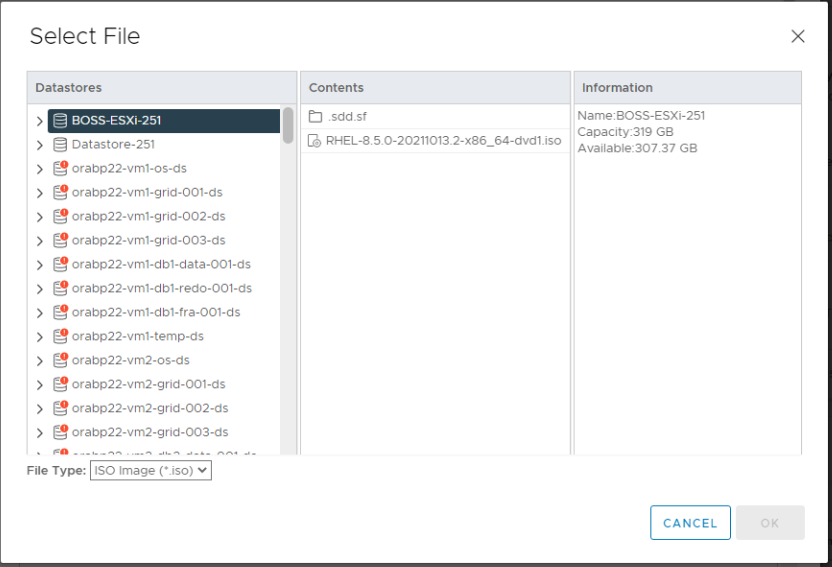
Figure 4: Create VM with Red Hat Enterprise Linux 8.5 ISO image
- Select Minimal Installation as base environment.
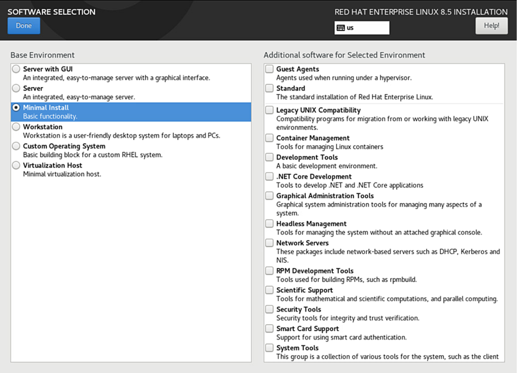 Figure 5: Software selection display page
- Configure public network from the Distributed switch.
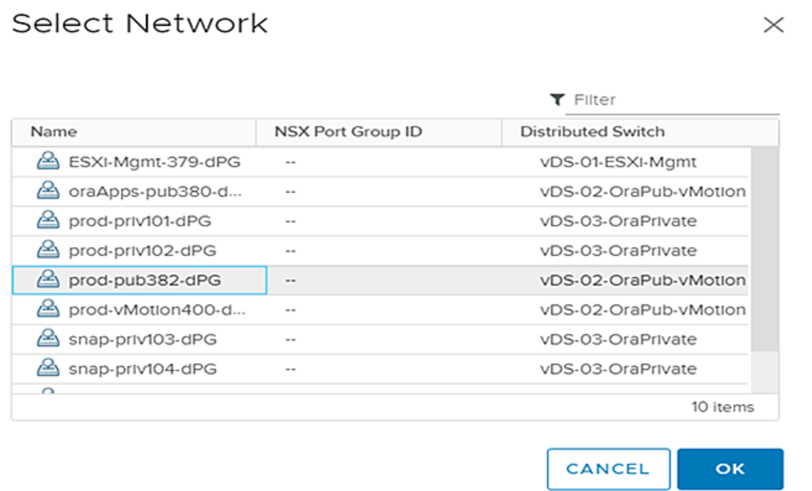
Figure 6: Select the Distributed switch for Public Network
- Add three additional SCSI drivers.
- From VCenter, select the VM and click Edit Settings > Add Devices > SCSI controller.
- Add three more SCSI controllers to SCSI controller 1 through 3.
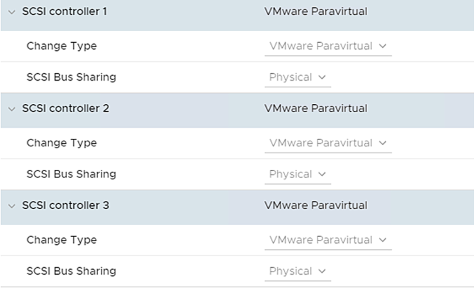 Figure 7: Select SCSI controllers
- Add hard disks.
- From vCenter, select the VM and click Edit Settings > Add Devices > Hard disks.
- Add all the VM hard disks on the list.
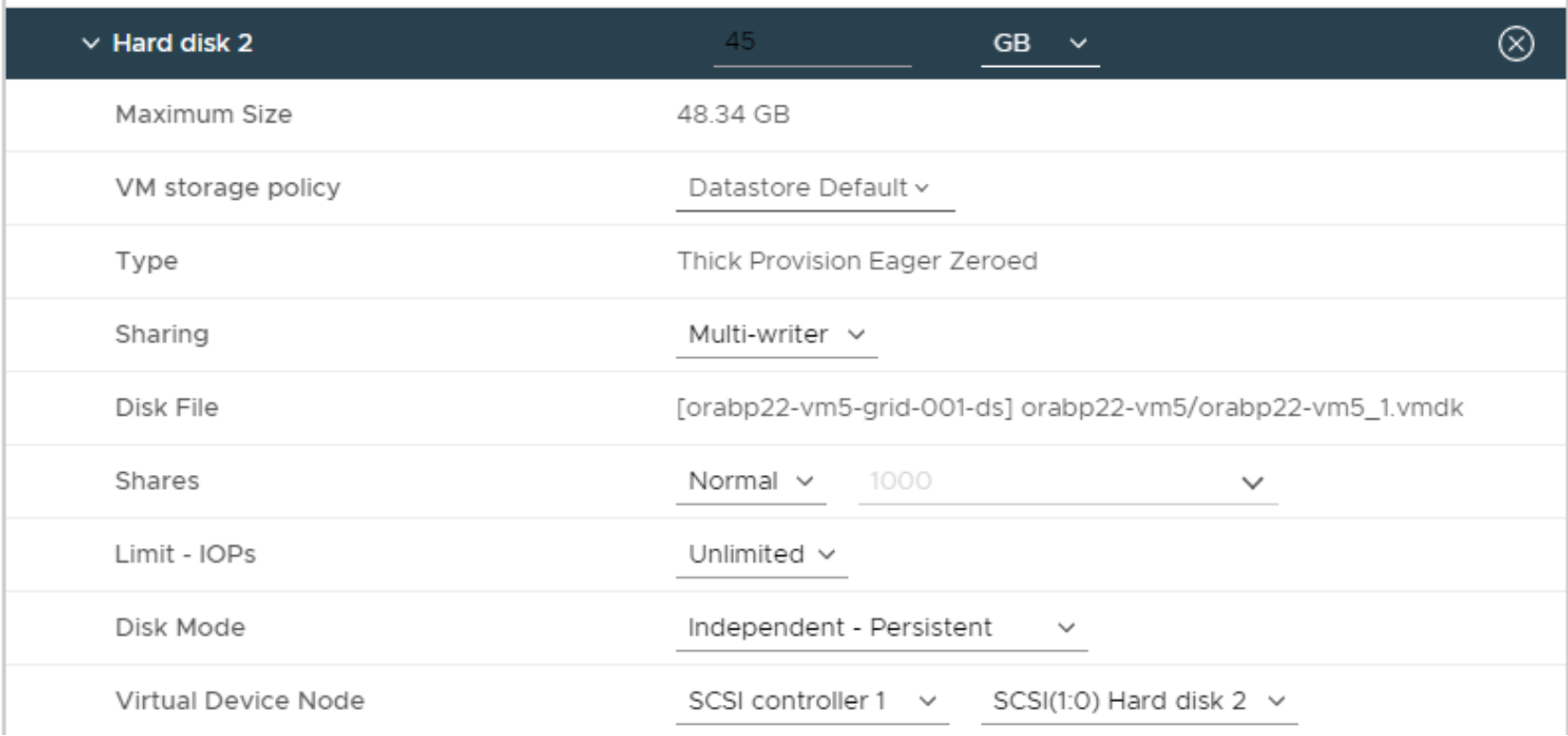
Figure 8: Add hard disks
VM operating system devices partition and prepare the volumes for Oracle ASM
- For each virtual disk, create a single partition that spans the entire disk and has a starting offset of 2,048 sectors. This ensures that the disk is correctly aligned, such that the start of each partition that is created on volume is aligned with the start of a physical sector of a disk or logical block of a LUN. Creating a partition on a disk also marks the disk that is used and can prevent the disk from being used for other purposes.
parted -s /dev/sdh mklabel msdos
parted -s /dev/sdh mkpart primary 2048s 100%
- Use the UDEV rule to assign Linux 0660 permission and ownership of these disks to the grid user, that is, the owner of the Oracle GI and Oracle ASM instance. In the following code sample, the UDEV rule is set for one of the disks as an entry of the custom UDEV rule script in /etc/udev/rules.d/95oracleasm.rules:
KERNEL=="sd[a-z]*[1-9]", SUBSYSTEM=="block", OPTIONS:= "nowatch", PROGRAM=="/usr/lib/udev/scsi_id -g -u -d /dev/$parent", RESULT=="368ccf09800cd6a0eaf106e5a2155cf92", SYMLINK+="oraudev/disks/ora-data1", OWNER="grid", GROUP="asmadmin", MODE="0660"
The string “368ccf09800cd6a0eaf106e5a2155cf92” is the SCSI ID of the device.
SCSI ID of devices can be found using the following command:
/usr/lib/udev/scsi_id -g -u -d /dev/sdX
Note: Oracle also provides ASMLIB and ASM Filter driver, which supersedes ASMLIB to configure disks. This driver is required to install the additional oraclesm kernel driver, oracleasm-support package, and oracleasmlib library.
- Run the Linux command # udevadm trigger and set the ownership of the device /dev/sdh1 as the following:
grid:asmadmin with 0660 permission and also create a soft link alias /dev/oraudev/disks/ora-data1 that points to /dev/sdh1.
You can use this soft link alias as the path of this device to create an Oracle ASM disk.
- Repeat step 2 and step 3 to create UDEV rules for all the database disks in the custom UDEV rule script.
/etc/udev/rules.d/95oracleasm.rules.
For example, creating these rules creates the device links:
/dev/oraudev/disks/ora-XXX as the following list.
Oracle grid infrastructure installation and upgrade
Oracle database installation and upgrade
Oracle database 19.3.0.0 Installation
Perform the following command to install Oracle database 19.3.0.0 on Red Hat Enterprise Linux operating system 8.5 in virtual machine:
oracle@dbhost1 dbhome_1]$ export CV_ASSUME_DISTID=OL7
[oracle@dbhost1 dbhome_1]$ ./runInstaller &
Select software only.
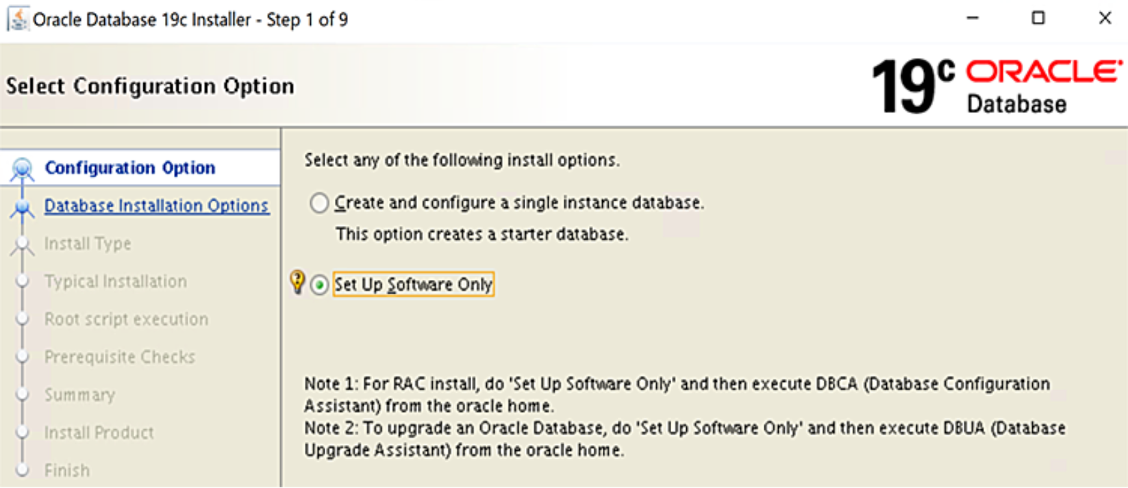
Figure 9: Oracle Database 19c installation
Use the installer UI steps to complete the installation.
Oracle Database 19cR15 Upgrade
Use the following steps to upgrade Oracle Database to 19.15.0.0:
- Apply patch 6880880 to the Oracle database home to upgrade the Opatch utility from 12_2.0.1.17 to 12.2.0.1.30
- Upgrade the Oracle database home from 19c base version to 19cRU15 by applying patch 33806152. Follow the update instructions in patch 33806152 readme.
The following example is the main patch apply step:
[oracle@obpvm4 patches]$cd /home/oracle/patches/33806152
[oracle@obpvm4 33806152]$ opatch prereq CheckConflictAgainstOHWithDetail -ph ./
[oracle@obpvm4 33806152]$$ opatch apply
ASM disk groups creation
Before creating a test database, we created four disk groups for DATA, REDO, FRA, and TEMP for the datafiles, REDO logs files, FRA/archive logs files and Temp files for the HammerDB test database.
Table 13 shows the volume mapping of ASM disk groups: DATA, REDO, FRA, and TEMP. For the baseline configuration, we included one volume for each of the DATA, REDO, and FRA disk groups.
Table 14: ASM disks and disk groups
|
Volume Group |
Volume Name |
VMware Datastore |
Volume size (GB) |
ASM device name |
Diskgroup |
|
orabp22-vm1-os |
orabp22-vm1-os |
orabp22-vm1-os-ds |
400 |
NA |
NA |
|
orabp22-vm1-db1 |
orabp22-vm1-db1-data-001 |
orabp22-vm1-data-001-ds |
1000 |
/dev/oraudev/disks/ora-data1 |
DATA |
|
orabp22-vm1-db1-redo-001 |
orabp22-vm1-redo-001-ds |
55 |
/dev/oraudev/disks/ora-redo1 |
REDO |
|
|
orabp22-vm1-db1-fra-001 |
orabp22-vm1-fra-001-ds |
60 |
/dev/oraudev/disks/ora-fra1 |
FRA |
|
|
orabp22-vm1-temp |
orabp22-vm1-db1-temp |
orabp22-vm1-temp-ds |
500 |
/dev/oraudev/disks/ora-temp1 |
TEMP |
To create these ASM disk groups, log in as the grid user and run the following asmca command:
$ asmca
Figure 10: ASM disk groups layout
Select the proper DISK Path for each disk group, as shown in Figure 11. After creating these disk groups, all disk groups should appear as shown in the following display:
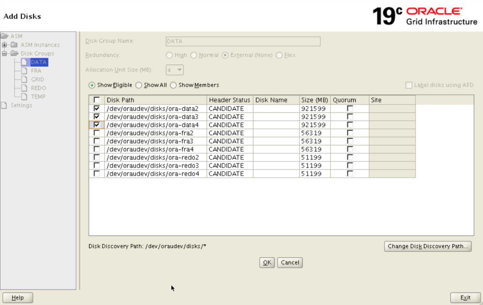
Figure 11: Available ASM disks
HammerDB test database configuration
We used HammerDB to generate an OLTP workload that simulates enterprise applications. We generated a significant load on the Oracle infrastructure to determine the performance difference between baseline configuration and best practices configuration.
Create a HammerDB test database
We began the test database environment configuration by creating a test database. We performed the dbca command as the Oracle user to create an Oracle database using the following disk groups:
- DATA disk group for database datafile and control files
- REDO disk group for online redo logs
- TEMP disk group for TEMP file
- FRA for Flash Recovery Area
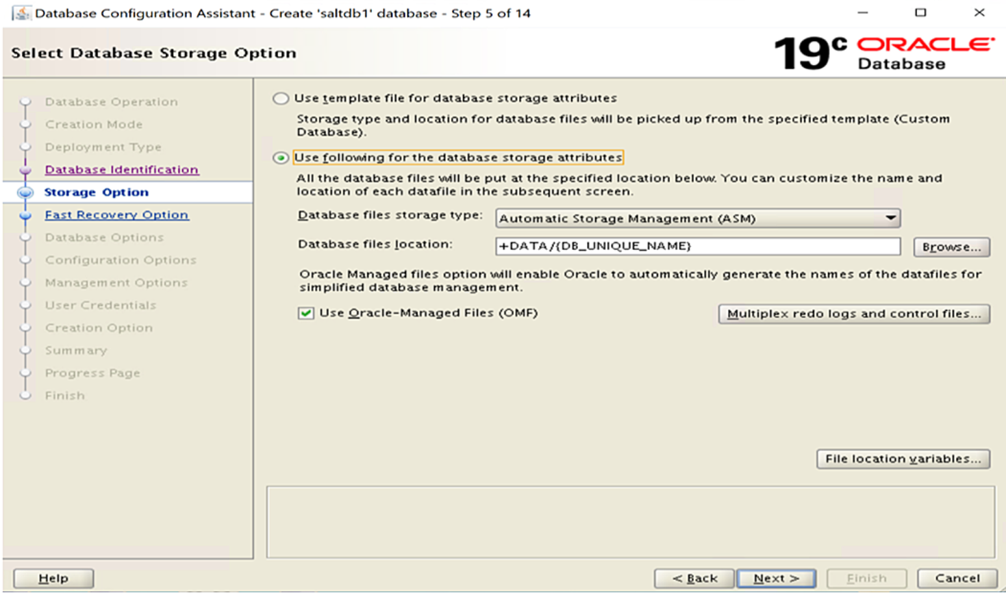
Figure 12: Creating a test database with dbca
Test database default settings
We used the following main performance related database settings or database limit settings for this HammerDB test in the baseline configuration.
Table 15: Test database default configuration
|
SGA_target |
64GB |
|
PGA_target |
10GB |
|
DB_BLOCK_SIZE |
8k |
|
Processes, sessions, transactions |
640 |
|
Sessions |
984 |
|
Transactions |
1082 |
|
Undo_management, |
Auto |
|
Undo tablespace |
UNDOTBS1 |
|
filesystem_io_options |
SETALL |
|
disk_async_io |
TRUE |
|
db_file_multiblock_read_count |
128 |
|
db_writer_process |
1 |
|
Redo log file size |
200 MB each |
|
Redo log file block size |
512 |
|
LOG_CHECKPOINT_INTERVAL |
0 |
|
LOG_CHECKPOINT_TIMEOUT |
1800 |
|
log_buffer |
115200 K |
|
Redo/temp files |
coarse |
In addition to these database parameters, we maintained the ASM disk group parameter AU Size to the default value of 4 MB in the baseline configuration.
Loading HammerDB TPCC OLTP testing configuration
The Hammer DB workload configuration is shown in the following table:
Table 16: HammerDB TPCC workload configuration
|
Setting Name |
Value |
|
Total transactions per user |
1,000,000 |
|
Number of warehouses |
5,000 |
|
Number of virtual users |
80 |
|
Minutes of ramp up time |
10 |
|
Minutes of test duration |
50 |
|
Use all warehouses |
Yes |
|
User delay (ms) |
100 |
|
Repeat delay (ms) |
100 |
|
Iterations |
1 |
In reviewing the configuration parameters, the overall profile can be labeled as an entry-level database. An entry-level database configuration provides a foundation to build upon best practices. Over the course of validating best practices the database configuration will change to optimize performance. This approach of starting with a minimal configuration and adding best practices has the benefit of enabling customers to address database growth challenges using these validated recommendations.
Storage best practices
Storage best practices overview
Storage default settings
The following list highlights default settings that we recommend maintaining for optimal storage performance:
- For mission critical Oracle databases, we recommend separating the following database components into different ASM disk groups:
- GRID disk group for Oracle grid infrastructure and Voting disks (if RAC is configured).
- DATA disk group for database files
- REDO disk group for online Redo logs
- TEMP disk group for Temp and FRA disk group for flashback logs and archive logs
- Follow Oracle ASM best practices to create ASM disk groups for GRID, DATA, REDO, FRA, and TEMP.
- Use multiple I/O controllers in VM hard disk configuration to distribute storage volumes and VM hard disks to multiple I/O controllers for I/O load balance.
As part of the storage layer tuning, we have tested the following parameters:
- PowerStore Multiple Volumes
- PowerStore Performance Policy
Multiple volume ASM Disk Groups
Storage configuration can directly influence database performance. This best practice validates that adding multiple storage LUNs for ASM disk groups optimizes database performance.
|
Category |
PowerStore Storage |
|
Product |
PowerStore 5000T |
|
Type of best practice |
Performance Optimization |
|
Day and value |
Day 1, Highly recommended |
Overview
To determine if a best practice provides value, it had to be tested against a baseline configuration of the database to validate performance. In the baseline configuration for database volumes, the DATA, REDO, and FRA disk group each consists of one LUN. Table 16 shows the baseline volume groups and LUNs configuration.
The baseline storage configuration followed the principle of separating database files into dedicated volume groups. For example, the Data files, Online Redo logs, and FRA files are in the same volume group, but separated from the Grid volume group and the Temp volume group. This allows the DBA to only snapshot the database without including the Grid and Temp files which are not necessary for a functional database snapshot. This also provides space savings if replication is used.
Table 17: Baseline volume group configuration
|
Volume Group |
Volume Name |
VMware Datastore |
Volume size (GB) |
Notes |
|
orabp22-vm1-os |
orabp22-vm1-os |
orabp22-vm1-os-ds |
400 |
Operating System |
|
orabp22-vm1-grid |
orabp22-vm1-grid-001 |
orabp22-vm1-grid-001-ds |
50 |
GRID |
|
orabp22-vm1-grid-002 |
orabp22-vm1-grid-002-ds |
50 |
||
|
orabp22-vm1-grid-003 |
orabp22-vm1-grid-003-ds |
50 |
||
|
orabp22-vm1-db1 |
orabp22-vm1-db1-data-001 |
orabp22-vm1-data-001-ds |
1000 |
Data files |
|
orabp22-vm1-db1-redo-001 |
orabp22-vm1-redo-001-ds |
55 |
Online redo logs |
|
|
orabp22-vm1-db1-fra-001 |
orabp22-vm1-fra-001-ds |
60 |
Flash Recovery Area |
|
|
orabp22-vm1-temp |
orabp22-vm1-db1-temp |
orabp22-vm1-temp-ds |
500 |
Temp files |
Table 18 shows the optimized PowerStore storage configuration. The volume groups remain intact, but additional LUNs were added for the DATA, REDO, and FRA disk groups. Using multiple LUNs for Oracle ASM disk groups improves database performance. The primary benefit of using multiple LUNs is that the operating system creates an I/O queue path per LUN. Since Oracle ASM spreads data evenly across all disks in a disk group, this would reduce any I/O bottleneck and provide higher I/O concurrency providing performance optimization and utilization. The following table shows the optimized PowerStore storage configuration for the Oracle database. In the optimized storage configuration, DATA, REDO, and FRA disk groups each has four LUNs. Compared to the baseline configuration, there are four times the number of I/O queue paths.
Table 18: Optimized PowerStore storage configuration
|
Volume Group |
Volume Name |
VMware Datastore |
Volume size (GB) |
Notes |
|
orabp22-vm1-os |
orabp22-vm1-os |
orabp22-vm1-os-ds |
400 |
Operating System |
|
orabp22-vm1-grid |
orabp22-vm1-grid-001 |
orabp22-vm1-grid-001-ds |
50 |
GRID |
|
orabp22-vm1-grid-002 |
orabp22-vm1-grid-002-ds |
50 |
||
|
orabp22-vm1-grid-003 |
orabp22-vm1-grid-003-ds |
50 |
||
|
orabp22-vm1-db1 |
orabp22-vm1-db1-data-001 |
orabp22-vm1-data-001-ds |
1000 |
Data files |
|
orabp22-vm1-db1-data-002 |
orabp22-vm1-data-002-ds |
1000 |
||
|
orabp22-vm1-db1-data-003 |
orabp22-vm1-data-003-ds |
1000 |
||
|
orabp22-vm1-db1-data-004 |
orabp22-vm1-data-004-ds |
1000 |
||
|
orabp22-vm1-db1-redo-001 |
orabp22-vm1-redo-001-ds |
55 |
Online redo logs |
|
|
orabp22-vm1-db1-redo-002 |
orabp22-vm1-redo-002-ds |
55 |
||
|
orabp22-vm1-db1-redo-003 |
orabp22-vm1-redo-003-ds |
55 |
||
|
orabp22-vm1-db1-redo-004 |
orabp22-vm1-redo-004-ds |
55 |
||
|
orabp22-vm1-db1-fra-001 |
orabp22-vm1-fra-001-ds |
60 |
FRA files |
|
|
orabp22-vm1-db1-fra-002 |
orabp22-vm1-fra-002-ds |
60 |
||
|
orabp22-vm1-db1-fra-003 |
orabp22-vm1-fra-003-ds |
60 |
||
|
orabp22-vm1-db1-fra-004 |
orabp22-vm1-fra-004-ds |
60 |
||
|
orabp22-vm1-temp |
orabp22-vm1-db1-temp |
orabp22-vm1-temp-ds |
500 |
Temp files |
Once the additional LUNs are created, these LUNS can be added to the ASM disk groups. The size of the LUNs for each ASM disk group should be determined by the size of the database. The PowerStore storage array has thin provisioning feature, meaning LUNs should be created larger than required. However, to truly benefit using thin-provisioned LUNs on the PowerStore, the use of Oracle “autoextend” clause when creating tablespaces is required. For detailed PowerStore best practices and features, see Storage Best Practices.
Recommendation
Our results indicated that having multiple LUNs for the ASM disk groups increased performance significantly for the following metrics:
- New Order per Minute (NOPM)
- Transactions per Minute (TPM)
- PowerStore IOPS
- Server CPU utilization
Based on these results, it is considered as a Day 1, Highly Recommended best practice.
Implementation steps
Before adding additional three LUNS/volumes to each ASM disk group, we performed the following tasks to present the additional volumes to the guest VM RHEL OS where the Oracle database resides.
- Present these volumes to the ESXi host and created the corresponded datastores based on these volumes
- Created the hard disks from these data stores and presented these hard disks to the guest VM Red Hat Enterprise Linux OS as VMDKs.
- Use these devices as a whole disk (/dev/sd?)
- Created udev rules to assign Linux 0660 permission and ownership of these devices to the grid user and create alias name such as ‘/dev/oraudev/disks/ora-data2’ for each device.
After performing these tasks, the following table shows the device names, their corresponding volume groups, and the ASM disk groups.
Table 19: Volume groups, data stores, UDEV devices and ASM disk groups
|
Volume Group |
VMware Datastore |
UDEV device name |
ASM DG |
|
orabp22-vm1-db1 |
orabp22-vm1-data-001-ds |
/dev/oraudev/disks/ora-data1 |
DATA |
|
orabp22-vm1-data-002-ds |
/dev/oraudev/disks/ora-data2 |
||
|
orabp22-vm1-data-003-ds |
/dev/oraudev/disks/ora-data3 |
||
|
orabp22-vm1-data-004-ds |
/dev/oraudev/disks/ora-data4 |
||
|
orabp22-vm1-redo-001-ds |
/dev/oraudev/disks/ora-redo1 |
REDO |
|
|
orabp22-vm1-redo-002-ds |
/dev/oraudev/disks/ora-redo2 |
||
|
orabp22-vm1-redo-003-ds |
/dev/oraudev/disks/ora-redo3 |
||
|
orabp22-vm1-redo-004-ds |
/dev/oraudev/disks/ora-redo4 |
||
|
orabp22-vm1-fra-001-ds |
/dev/oraudev/disks/ora-fra1 |
FRA |
|
|
orabp22-vm1-fra-002-ds |
/dev/oraudev/disks/ora-fra2 |
||
|
orabp22-vm1-fra-003-ds |
/dev/oraudev/disks/ora-fra3 |
||
|
orabp22-vm1-fra-004-ds |
/dev/oraudev/disks/ora-fra4 |
For the baseline configuration, each ASM disk group of DATA, REDO, and FRA only has a single volume. For example, DATA disk group has one volume: ‘/dev/oraudev/disks/ora-data1’. To add the additional three volumes to the ASM disk groups, DATA, REDO, and ARCH, ensure that all four LUNs in the same disk group are of the same size. Perform the following SQL statement in the ASM instance to add the three ASM disk groups, DATA, REDO, and FRA:
SQL> ALTER DISKGROUP data ADD DISK
'/dev/oraudev/disks/ora-data2' NAME DATA_0001,
'/dev/oraudev/disks/ora-data3' NAME DATA_0002,
'/dev/oraudev/disks/ora-data4' NAME DATA_0003;
SQL> ALTER DISKGROUP redo ADD DISK
'/dev/oraudev/disks/ora-redo2' NAME REDO_0001,
'/dev/oraudev/disks/ora-redo3' NAME REDO_0002,
'/dev/oraudev/disks/ora-redo4' NAME REDO_0003;
SQL> ALTER DISKGROUP fra ADD DISK
'/dev/oraudev/disks/ora-fra2' NAME FRA_0001,
'/dev/oraudev/disks/ora-fra3' NAME FRA_0002,
'/dev/oraudev/disks/ora-fra4' NAME FRA_0003;
It is recommended to set up the ASM disk groups with multiple LUNs during the initial configuration but if this is an existing database, you can run these SQL statements to add volume to ASM disk groups while the database is still running. It is preferable to run these statements outside of the database workloads’ peak time, as adding disk volume operations results in data rebalancing and may cause a significant performance overhead. The rebalancing power is defined by the ASM_POWER_LIMIT initialization parameter (default value = 1, range to 1024). The higher the limit, the faster a rebalance operation may complete, and the rebalance results in more performance overhead.
To monitor the status of the rebalancing operation, run this SQL statement to check the operation status:
SQL> select INST_ID, OPERATION, STATE, POWER, SOFAR, EST_WORK, EST_RATE, EST_MINUTES from GV$ASM OPERATION;
INST_ID OPERA STAT POWER SOFAR EST_WORK EST_RATE EST_MINUTES
---------- ----- ---- ---------- ---------- ---------- ---------- -----------
1 REBAL WAIT 1 0 0 0 0
1 REBAL RUN 1 14185 179546 7085 23
1 REBAL DONE 1 0 0 0 0
In this example, the output shows three rebalancing operations: the first is done (bottom), the second is running (middle), and the third is waiting (top). For the second row, the report shows:
- EST_WORKD=179,546 - estimated number of Allocation Units that must be moved
- SOFAR = 14,185 - number of Allocation Units that have been moved so far
- EST_RATE=7,085 - number of Allocation Units that are moved per minute
- EST_MINUTES= 23 – remaining estimated amount of time (23 minutes) =
PowerStore: Volume Performance Policy
Volume performance can be managed in PowerStore by adjusting the performance policy to high, medium, or low. Selecting a performance policy sets a relative priority for the volume by using a share-based system that prioritizes the higher performance policy when resources are constrained. The performance policy does not impact on system behavior unless some volumes have a low performance policy setting while other volumes are set to medium or high.
This section discusses the Volume Performance Policy of the PowerStore. This best practice validates that changing the volume performance policy for the database volumes from the default (medium) to “High” may optimize database performance in certain configurations.
|
Category |
PowerStore Storage |
|
Product |
PowerStore 5000T |
|
Type of best practice |
Performance Optimization |
|
Day and value |
Day 3, Fine Tuning |
Overview
To determine if changing the volume performance policy provides value, it had to be tested against the baseline using the default value (medium). In the baseline configuration, the database volumes for the Oracle DATA, REDO, and FRA ASM disk groups were configured with the “medium” performance policy.
Table 19 below shows which volumes were configured with the performance policy of “High”.
Table 20: Volume Performance Policy Settings
|
Volume Group |
Volume Name |
VMware Datastore |
Volume Performance Policy |
Notes |
|
orabp22-vm-db1 |
orabp22-vm1-db1-redo-001 |
orabp22-vm1-redo-001-ds |
High |
REDO |
|
orabp22-vm1-db1-redo-002 |
orabp22-vm1-redo-002-ds |
High |
||
|
orabp22-vm1-db1-redo-003 |
orabp22-vm1-redo-003-ds |
High |
||
|
orabp22-vm1-db1-redo-004 |
orabp22-vm1-redo-004-ds |
High |
Recommendation
There was no change in performance based on the test results after changing the volume performance policy to High for the Oracle REDO disk group. Although, changing the volume performance policy for the REDO disk group yielded no gain in performance, it is still recommended as this could potentially help improve database performance when the PowerStore storage array is heavily used due to workload consolidation. Therefore, this is considered as a Day 3, Fine Tuning best practice.
Implementation steps
To change the volume performance policy for the volumes, use the PowerStore Manager and follow the instructions from PowerStore Manager Overview.
The following figure shows the performance policy for the volumes of VM1.
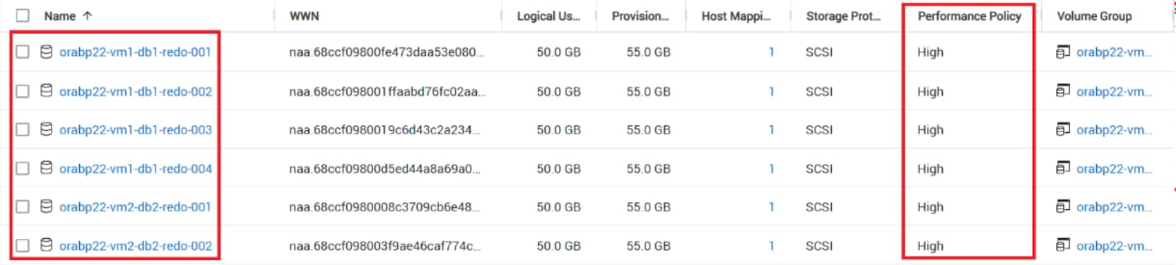
Figure 13: Volume Performance Policy settings
Operating system and database best practices
Red Hat Enterprise Linux: Oracle Tuned Profile
Red Hat Enterprise Linux: HugePages
Red Hat Enterprise Linux: Disk I/O Scheduler
Red Hat Enterprise Linux: NTP Protocol
Oracle 19c Database: Increase the Redo Log Size
Oracle 19c Database: High Priority Processes
Server Best practices
Server best practices overview
This chapter focuses on server configuration best practices. A server configuration can be optimized by tuning the sub-components such as CPU, memory etc. Dell servers offers a wide range of sub- component parameters as part of the server BIOS which can be configured.
As part of Server layer optimization, we have tested multiple parameters that are available in server BIOS. The test cases and results are discussed in detail here.
PowerEdge R750xs: Database Optimized Performance Workload Profile
By default, the Database Optimized Performance (DOP) profile is not enabled on the PowerEdge R750xs server. In this best practice we selected the DOP profile in BIOS and evaluated its impact on performance.
|
Category |
PowerEdge |
|
Product |
PowerEdge R750xs server |
|
Type of best practice |
Performance Optimization |
|
Day and value |
Day 1, Highly Recommended |
Overview
A BIOS profile is an easy way to apply firmware values that optimize the system. Below is a list of BIOS settings that are automatically changed by selecting the DOP profile:
- Virtualization Technology (VT): Default is ENABLED, changed to DISABLED with the DOP profile. When VT is enabled, firmware settings are configured for enhanced support of hypervisors. Thus, with VT there is greater integration with virtualization that can optimize virtualization on the server. The DOP profile disables VT as many databases are not virtualized. As the Oracle databases have been virtualized in our best practice infrastructure, the Engineering team enabled virtualization technology after it had been disabled by the DOP profile.
- System Profile: Default is Performance Per Watt (DAPC) and changed to Performance. DAPC is Dell’s proprietary implementation of dynamic processor management. Selecting the DOP profile changes the system profile from the default to Performance. Instead of the server balancing performance per watt to drive cost savings, the system is configured for maximum performance.
- CPU Power Management: Default system DBPM and changed to Max Performance. CPU Power Management controls use of processor performance states. By default, CPU Power Management uses Demand-Based Power Management (DBPM), which enables processor operating frequency and voltage to be dynamically adjusted. The DOP profile changes CPU Power Management to a static state of Maximum Performance.
Other system profile changes include:
- C1E: Default Enabled, changed to Disabled. Disables DIMM CKE power down and QPI power management.
- C States: Default Enabled, changed to Disabled. Disables C-states and DIMM self-refresh.
- Uncore Frequency: Default is Dynamic UFS, changed to Maximum. Setting to Maximum enables best performance of the cores and uncore during runtime.
- Energy Efficient Policy: By default the balanced performance policy is used. This setting was changed to Performance, which instructs the processors to operate at the highest performance level.
- CPU Interconnect Bus Link Power Management: Default Enabled, changed to Disabled.
- PCI ASPM L1 Link Power Management: Default Enabled, changed to Disabled.
Overall, the benefit of the Data Optimized Performance is setting several firmware settings to maximum performance. The only exception made in our validation tests was changing Virtualization Technology back to its default value of Enabled. However, for customers with physical (non-virtual) database deployments it is recommended to keep the DOP profile change for VT to Disabled.
Recommendation
Setting the Database Optimization Performance profile in the BIOS resulted in a performance improvement in our testing with virtual machines for the following metrics:
- New Order per Minute (NOPM)
- Transactions per Minute (TPM)
- PowerStore IOPS
- Server CPU utilization
This practice is categorized as a Day 1, Highly Recommended best practice.
Implementation steps
To set the Database Optimized Performance Workload Profile:
- Log into the iDRAC console and navigate to BIOS settings
- In System Profile Settings, select the Database Optimized Performance Profile in the Workload profile dropdown list
To enable Virtualization Technology on the iDRAC console:
- Navigate to Processor Settings
- Select Enabled for Virtualization Technology
These settings are described in Table 22.
Table 22: Database Optimized Performance profile
|
System Setup Screen |
BIOS Attribute Name |
BIOS Default Setting |
New setting with DBOP profile |
|
Processor Settings |
Virtualization Technology |
Enabled |
Disabled |
|
|
x2APIC mode |
Enabled |
Disabled |
|
System Profile |
System Profile |
Performance Per Watt (DAPC) |
Performance |
|
CPU Power Management |
System DBPM (DAPC) |
Maximum |
|
|
C1E |
Enabled |
Disabled |
|
|
C State |
Enabled |
Disabled |
|
|
Uncore Frequency |
DynamicUFS |
Maximum |
|
|
Energy Efficient Policy |
Balanced Performance |
Performance |
|
|
Monitor/Mwait |
Enabled |
Enabled |
|
|
CPU Interconnect Bus Link Power Management |
Enabled |
Disabled |
|
|
PCI ASPM L1 Link Power Management |
Enabled |
Disabled |
Use the following steps to set the DOP Workload Profile:
- Log in to the iDRAC console and go to BIOS settings
- In System Profile Settings, select DataBase Optimized Performance Profile in the Workload profile dropdown list
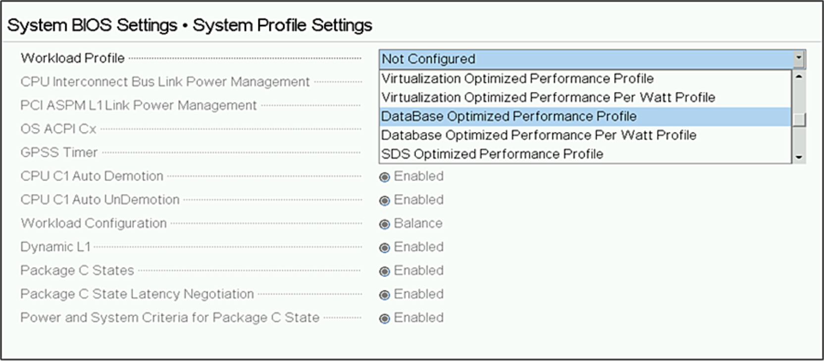 Figure 14: Set the Database Optimized Performance Workload Profile
Additional Resources
Setting up BIOS on 15th Generation (15G) Dell PowerEdge Servers
PowerEdge R750xs: Enabling Processor x2APIC Support
By default, the x2APIC BIOS setting is disabled on the PowerEdge R750xs server. In this best practice, we enabled the x2APIC setting to evaluate the impact on performance.
|
Category |
PowerEdge |
|
Product |
PowerEdge R750xs server |
|
Type of best practice |
Performance Optimization |
|
Day and value |
Day 3, Fine-Tuning |
Overview
The x2APIC is Intel’s Advanced Programmable Interrupt Controller design to improve efficiency in multiprocessor computer systems. An interrupt is a request by the software for the processor to respond to an event. For example, if an operating system requests that the processor suspend current activities and the processor accepts this request, the state of the current activities is saved, and the new request is processed.
The x2APIC is Intel’s most recent Advanced Programmable Interrupt Controller. Enhancements to x2APIC include support for more processors and improved performance. The PowerEdge R750xs we used for testing best practices had two Intel Xeon Gold 6338 processors each with 32 cores for a total of 64 cores in the server. We also used VMware vSphere 7.3 to virtualize the Oracle database. Enabling x2APIC should create efficiencies for the PowerEdge multi-processor system and optimize the interrupt management of virtual machines.
Recommendation
Overall, the best practice of enabling x2APIC in BIOS can provide a minor improvement in the system performance. Enabling x2APIC is a Day 3, Fine-Tuning recommendation with these considerations:
- For new PowerEdge servers, consider enabling the x2APIC BIOS setting if the virtualization and/or operating system supports the new interrupt controller.
- For existing PowerEdge servers, consult support documentation and consider enabling this BIOS setting at the next maintenance window.
Implementation steps
To enable the x2APIC BIOS setting, log in to iDRAC and do the following:
- Click the Configuration pulldown menu
- Click the BIOS Settings and Open Processor Settings tab
- Navigate to x2APIC Model and select the Enabled radio button
- At the bottom of the page, click Apply and Reboot
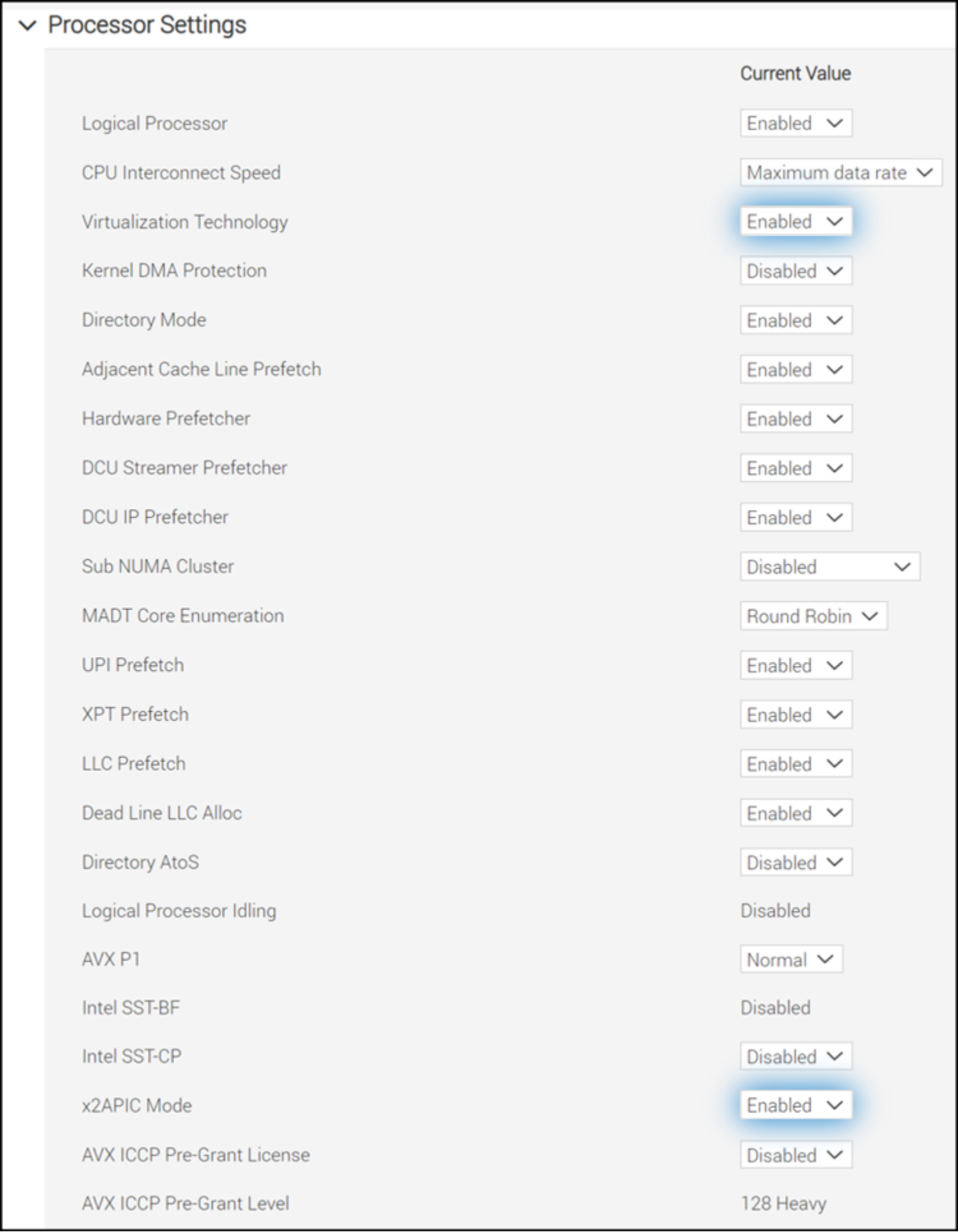
Figure 15: Enable Virtualization Technology Setting
Additional resources
Setting up BIOS on 15th Generation (15G) Dell PowerEdge Servers
PowerEdge R750xs: Dell Controlled Turbo
The PowerEdge servers come with the Dell Controlled Turbo feature which controls the turbo engagement of the CPUs. This feature can increase performance in both single-threaded and multithreaded applications.
|
Category |
PowerEdge |
|
Product |
PowerEdge R750xs |
|
Type of best practice |
Performance Optimization |
|
Day and value |
Day 1, Highly Recommended |
Overview
The Dell Controlled Turbo setting allows the CPUs to run at maximum speed. This option only works if the system profile is set to performance in the BIOS. In this best practice, we enabled the Dell Controlled Turbo with the Database Optimization Performance profile.
Recommendation
After enabling the Dell Controlled Turbo option, the following test metrics gained an increase in performance and is considered as a Day 1, Highly Recommended best practice.
- New Order per Minute (NOPM)
- Transactions per Minute (TPM)
- PowerStore IOPS
- Server CPU utilization
Implementation steps
To enable Dell Controlled Turbo, log in to iDRAC and do the following:
- Click the Configuration pulldown menu
- Click the BIOS settings
- Navigate to Processors
- Select Dell Controlled Turbo
- Select Enabled in the dropdown list
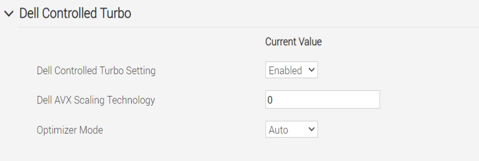
Additional resources
Enable Dell Controlled Turbo on 15th Generation (15G) Dell PowerEdge Server.
Disable unused Integrated devices and turn off serial communication
By default, PowerEdge servers have USB and other ports enabled. In this best practice USB and serial ports were disabled as both a security and performance best practice.
|
Category |
PowerEdge |
|
Product |
PowerEdge R750xs |
|
Type of best practice |
Performance Optimization |
|
Day and value |
Day 3, Fine-Tuning |
Overview
It is not expected that disabling USB ports and serial communication on servers will significantly improve performance, however, it is a good security practice. In this best practice the following ports were disabled in BIOS:
- User accessible USB ports
- Internal USB ports
- iDRAC Direct USB port
- Serial communication
Recommendation
Although disabling unused integrated devices showed no improvement, it is still considered as a Day 3, Fine Tuning best practice for security purposes.
Implementation Steps
Go to IDRAC > Configuration > BIOS settings > Integrated Devices and make the following changes:
- User Accessible USB Ports setting from All Ports On to All Ports Off
- Internal USB Port setting from On to Off
- iDRAC Direct USB Port setting from On to Off
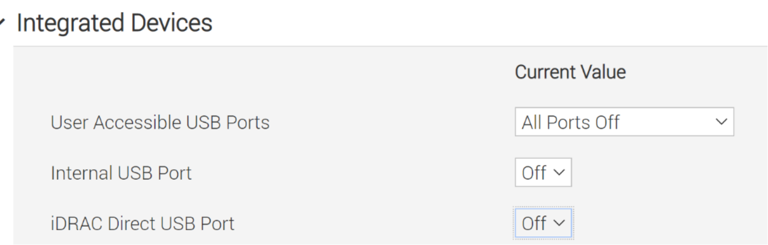
Additional Resources
Setting up BIOS on 15th Generation (15G) Dell PowerEdge Servers
VMFS to vVols migration
vVols overview
Migration
Migrating to vVols can be achieved easily by implementing the steps outlined in this chapter.
The migration process can be achieved by using the following procedure:
vVols configuration and migration process
- Time synchronization
- Storage provider registration
- Create storage container
- Create virtual datastore for vVols
- Migrate the datastore and disks from VMFS to vVols using storage vMotion
It is recommended to synchronize the time for all the hosts and vCenter Server instances.
Time Synchronization
Perform the following steps for all the hosts that will use vVols.
1. Select the host in the vSphere inventory.
2. Click the configure tab.
3. In the System section, select Time Configuration.
4. Click Add service or Edit and set up the NTP server.
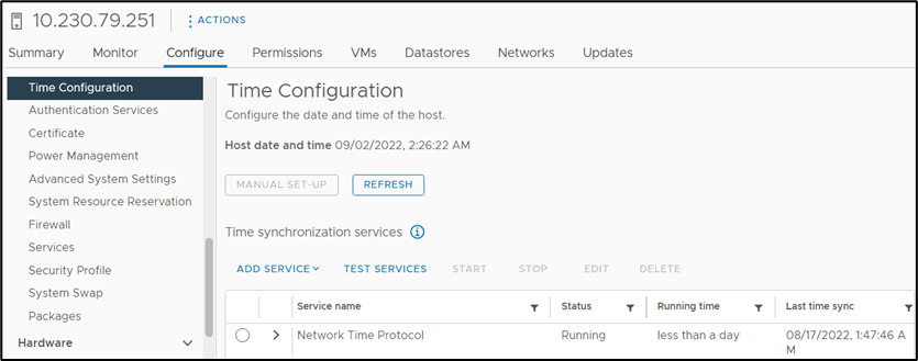
Figure 20. vSphere Time Configuration
5. Select Use Network Time Protocol (Enable NTP client).
6. Enter the IP addresses of the NTP servers to synchronize with.
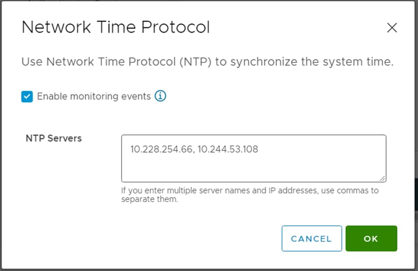
Figure 21. Time Configuration: NTP Servers Setting
7. Click OK. The host synchronizes with the NTP server.
8. Stop/Start as required.
Storage Provider Registration
To use vVols, The VASA provider must be registered with the vCenter. The storage capabilities are exported and presented to VMware based virtual infrastructure by using the protocol end points enabled by VASA.
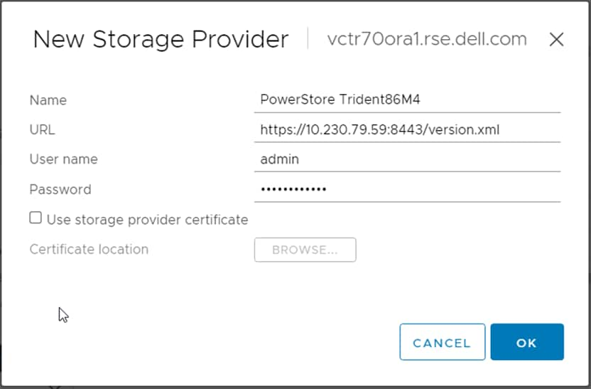
Figure 22. VASA Storage Provider Registration
Storage Provider Registration Procedure
1. Login to vSphere client.
2. Go to vCenter Server in the vSphere Web Client navigator.
3. Click the Configure tab and click Storage Providers.
4. Click the + Add icon to register a storage provider.
5. Enter the connection details for the new storage provider, including the name, URL, and credentials.
6. Click OK to complete the registration.
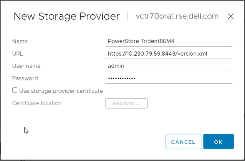
Figure 23. VASA Storage Provider Registration
7. The storage provider VASA has been successfully registered with the vCenter as shown in Figure 22.
8. Once the VASA is registered, create a vVol based datastore to utilize vVol based services
Virtual datastore creation procedure
1. Login to the vSphere Web Client.
2. Select the host in the vSphere inventory.
3. Right-click on the host and select the storage menu.
4. Click New Datastore.
5. Enter a unique datastore name.
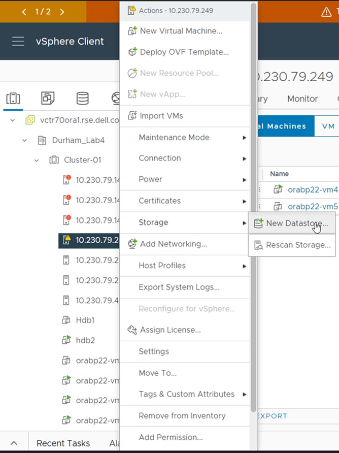
Figure 24. vVol Virtual Datastore Creation
6. Select vVol as the virtual datastore type.
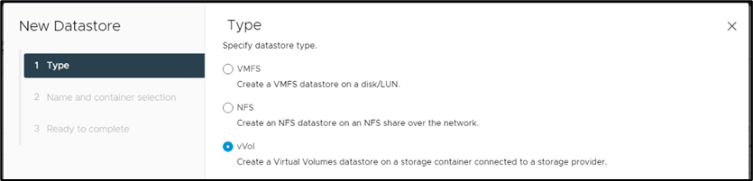
Figure 25. vVol Virtual Datastore Creation
7. Select the appropriate backing storage container which refers to the VASA that has been previously registered. This backing container will be used to host the virtual volumes.
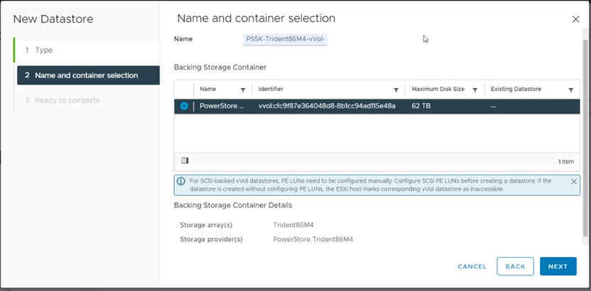
Figure 25. vVol Virtual Datastore Creation
8. Click next to review the selections and click Finish.
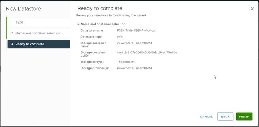
Figure 26. vVol Virtual Datastore Creation
9. At the end of the procedure, the newly created datastore can be viewed on the host.
10. To access the datastore on additional host(s), the datastore must be explicitly mounted on the required hosts based on the need.
Mounting the Virtual Datastore on additional hosts
1. Perform this procedure from the Storage view of the vSphere Client.
2. From the vSphere Client, go to the Storage view tab.
3. Right-click on the preferred vVol virtual datastore and click Mount Datastore to Additional Hosts
4. Select the available hosts to mount the Virtual Datastore and click OK.

Figure 27. vVol Virtual Datastore Host Connectivity
Virtual Machine Migration with Storage vMotion
1. Select the required virtual machine in the vSphere inventory and click Migrate.
2. Select Change storage only and click Next.
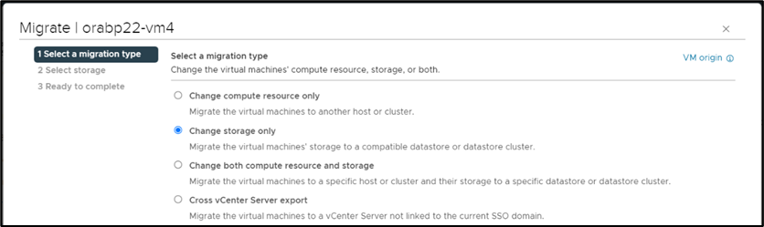
Figure 28. Storage Migration: VMFS to vVol
3. Select the vVol datastore destination storage, virtual disk format (thick provisioning), and click Next.
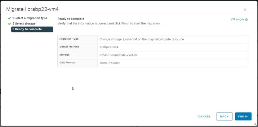
Figure 29: Storage Migration: VMFS to vVol
4. Review the migration details including migration type, virtual datastore target, and disk format settings. Click Finish.
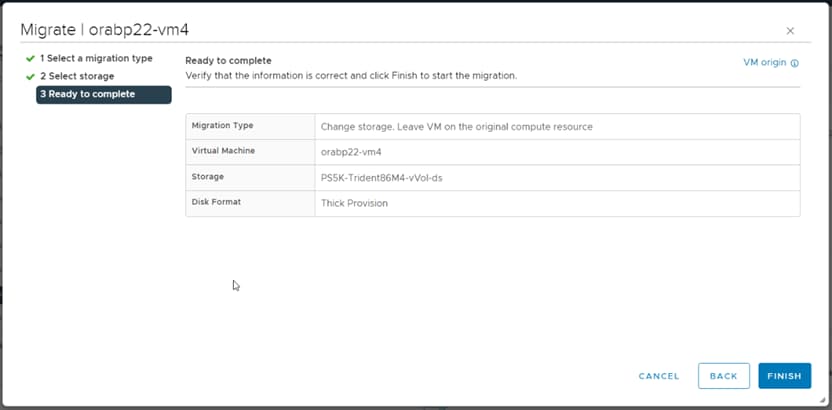
Figure 30. Storage Migration: VMFS to vVol
5. Depending on the number and size of the source virtual disks, it can take several minutes to complete the migration from VMFS to vVols.
6. You can check the status of the migration under the recent tasks tab of the vSphere client.

Figure 31. Storage Migration: VMFS to vVol
7. This migration process will create the necessary virtual volumes in the storage container of the storage system, as shown in Figure 32.
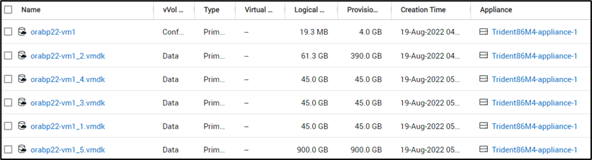
Figure 32. Storage Migration: Virtual Volumes
8. Upon the completion of migration, we can confirm the availability and mapping of the new vVol datastore by browsing to the datastores tab of the vm.
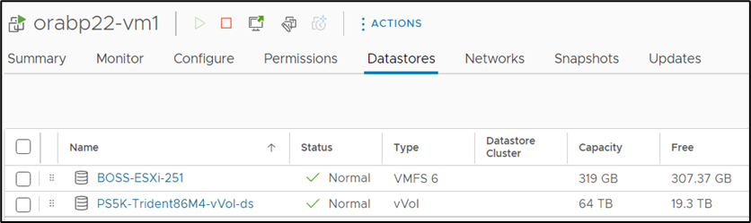
Figure 33. Post Storage Migration: VM with vVol Datastore
See vSphere Virtual Volumes (vVols) and vVols Getting Started Guide for more information about implementing and migrating vVols.