A Reference Guide to Vostro Laptop Diagnostic Indicators
Summary: The following article is a reference guide to the codes available on each model of Vostro laptop and what those codes indicate.
This article applies to
This article does not apply to
This article is not tied to any specific product.
Not all product versions are identified in this article.
Instructions
Dell Vostro laptops have a long history of integrated diagnostic indicators. The following methods are used to indicate at which point during the Power-On Self-Test (POST) a laptop is having issues:
- Audible beeps
- Power buttons that display different states and colors
- Specific diagnostics LEDs
- A combination of them all
The following article is a reference guide to the codes available on each model and what those codes mean. These change through the various models and years. These indicators are merely a starting point that narrows down any troubleshooting you must carry out to identify the cause of your current issue. You can use this to narrow down the proper troubleshooting guide you require. Alternatively, you can contact technical support for further help and they are looking for these indicators as well.
Table of Contents:
- Diagnostic LEDs for the Vostro laptop series (2015 to 2025)
- Diagnostic LEDs for the Vostro laptop series (2010 to 2015)
- Diagnostic LEDs for the Vostro laptop Series (Prior to 2010)
- Vostro laptop Audible Beep Codes
- Glossary of Acronyms
Note: For all the tables below, remember that the diagnostic LEDs only serve as an indicator of the progress through the POST process. These LEDs do not indicate the problem that caused the POST routine to stop.
Note: You are experiencing a No Boot if your laptop completes POST without stopping on a particular error code and then gives a black screen. The most likely reason is an issue with the operating system or storage media.
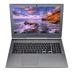
Diagnostic LEDs for the Vostro laptop series (2015 to 2025)
With the latest series, the diagnostics indicator Beeps have mostly been removed from these laptops. Instead the Power Button state now gives a blink and color shift pattern to indicate where it is having a problem.
Note: Click the title of the section that you want to open below, in order to see the contents.
Note: Diagnostic Error Codes always supersede any other use of the LED. For instance, battery codes for Low Battery or Battery Failure situations are not displayed when Diagnostic Error Codes are being displayed.
| Power Source | Status | Power State | Description |
|---|---|---|---|
| AC Adapter | Off | S0 - S5 | Fully Charged |
| White | S0 - S5 | Charging | |
| Battery | Off | S0 - S5 | Battery Discharging |
| Solid Amber | S0 - S5 | Low to Critically Low |
- S0 - ON - System is on
- S4 - Hibernate - System in hibernation mode
- S5 - OFF - System is off
Note: The blinking patterns consist of two sets of numbers. These are the First Group (Amber Blinks), and the Second Group (White Blinks).
Example: No Memory detected (2, 3), The Battery LED blinks two times amber followed by a pause, then blinks three times white, pause, and so on. This pattern continues until the laptop is turned off.
- First Group: The Battery LED blinks in Amber up to nine times then pauses for 1.5 seconds before running the second group.
- Second Group: The Battery LED blinks in White up to nine times then pauses for 3 seconds before running the first group again.
Example: No Memory detected (2, 3), The Battery LED blinks two times amber followed by a pause, then blinks three times white, pause, and so on. This pattern continues until the laptop is turned off.
| Power LED | Problem Description | Suggested Resolution | |
|---|---|---|---|
| Amber | White | ||
| 2 | 1 | CPU Failure |
|
| 2 | 2 | System Board: BIOS ROM Failure |
|
| 2 | 3 | No Memory/RAM detected |
|
| 2 | 4 | Memory/RAM failure |
|
| 2 | 5 | Invalid Memory Installed |
|
| 2 | 6 | System board, Chipset Error |
|
| 2 | 7 | LCD failure |
|
| 3 | 1 | CMOS battery failure |
|
| 3 | 2 | PCI or Video card/chip failure |
|
| 3 | 3 | BIOS Recovery 1 |
|
| 3 | 4 | BIOS Recovery 2 |
|
| 3 | 5 | Power Rail Failure |
|
| 3 | 6 | SBIOS Flash Corruption |
|
| 3 | 7 | ME Error |
|
| 4 | 1 | Memory Dual Inline memory module (DIMM) Power rail failure |
|
| 4 | 2 | CPU Power Cable Connection Issue |
|
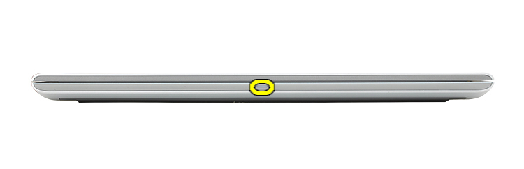
Diagnostic LEDs for the Vostro laptop series (2010 to 2015)
With this series of laptops, the Diagnostic indicators changed to use two different methods depending on the model of laptop you have:
- One method uses only the Power LED as an indicator. The Diagnostic LED is now the state of the Power LED and how many times it blinks at you.
- The other method uses the beep codes from the beep code section.
| Power LED State | Description |
|---|---|
 |
|
 |
The laptop is in S0 state, the normal power state of a functioning machine. The BIOS turns the LED to this state to indicate it has started fetching opcodes. |
 |
Laptop is in a low power state, either S1 or S3. This does not indicate a fault condition. |
Warning: The power LED only serves as an indicator of the progress through the POST process. These LEDs do not indicate the problem that caused the POST routine to stop.
Note: The Power button has a bicolor LED. In a No Post situation, it displays an Amber LED blinking pattern: The Power Button LED shall blink the corresponding LED codes for the corresponding fault condition. The repeated pattern has a three second long pause inserted in the middle.
Example: No Memory detected, Power Button LED blinks two times followed by a pause, blinks two times, pause, and so on. This pattern continues until the laptop is turned off.
Example: No Memory detected, Power Button LED blinks two times followed by a pause, blinks two times, pause, and so on. This pattern continues until the laptop is turned off.
| LED Behavior | Problem Description | Next Steps |
|---|---|---|
| 1 | System Board: BIOS ROM Failure |
|
| 2 | No Memory/RAM detected |
|
| 3 | System board, Chipset Error, Clock Failure, Gate A20 Failure, Super I/O Failure, Keyboard controller failure |
|
| 4 | Memory/RAM failure |
|
| 5 | CMOS battery failure |
|
| 6 | Video card/chip failure |
|
| 7 | CPU Failure |
|
This indicates the Battery power management LEDs codes.
| Power Source; Battery Charge | Off/Hibernate | Standby | On |
|---|---|---|---|
| Power LED (All; 0-100% charge) | Off | Blinking White light (repeated) | Solid White |
| Battery LED (AC Adapter; 98-100% charged) | Off | Off | Off |
| Battery LED (AC Adapter; Below 98% charging) | Solid White | Solid White | Solid White |
| Battery LED (Battery; discharging) | Off | Solid Amber | Solid Amber |
| Battery LED (Battery; Below 10% critically low) | Off | Off | Off |
| Hard drive LED | Off | Off | White when active |
| Camera LED (All sources; 0-100% charge) | Off | Off | Sold White when streaming data |
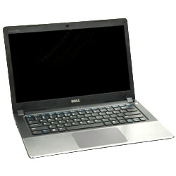
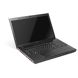
Diagnostic LEDs for the Vostro laptop series (Prior to 2010)
This series used power button LED states and a diagnostics LED pack on laptops.
Note: Click the title of the section that you want to open below, in order to see the contents.
These models had a block of keyboard status LEDs on the front of the chassis that either lit up solid white, flashed white or were Off. The table below shows what these indicate.

| Icon | Description |
|---|---|
 |
Caps Lock light - Turns on when the Caps Lock is engaged. |
 |
Scroll Lock light - Turns on when the Scroll Lock is engaged. |
 |
Number Lock light - Turns on when the Number Lock is enabled. |
| Flash Code | LED Pattern | Description | Next Step |
|---|---|---|---|
 |
Flash-On-On | The microcontroller is handing control of the laptop to the processor. This code persists if no processor is detected. |
|
 |
On-Flash-On | The memory has encountered an error. |
|
 |
Flash-Flash-Flash | A system board component is faulty. |
|
 |
Flash-Flash-On | The video card is preventing the laptop from completing POST. |
|
 |
Flash-Flash-Off | The keyboard is preventing the laptop from completing POST. |
|
 |
Flash-Off-Flash | The USB controller encountered a problem during initialization. |
|
 |
On-Flash-Flash | No SODIMMs are installed. |
|
 |
Flash-On-Flash | The LCD encountered a problem during initialization. |
|
 |
Off-Flash-Flash | The modem is preventing the laptop from completing POST. |
|
If the laptop is running on a battery, the battery light operates as follows:
- Off — The battery is adequately charged (or the laptop is turned off).
- Flashing Amber — The battery charge is low.
Vostro laptop audible Beep codes
In addition to the various types of diagnostics LEDs, there are some audible beep codes across some of the models of these laptops.
These codes are recognized across manufacturers and have remained the same for some time.
The key to these codes is displayed in the table below.
Note: Click the title of the section that you want to open below, in order to see the contents.
| Beep Code | Description | Failure Coverage | Suggested Action |
|---|---|---|---|
| 1 | System board covers BIOS corruption or ROM error. | System board BIOS ROM failure | Run the Dell Diagnostics |
| 2 | No Memory/RAM Detected | No memory detected | Troubleshoot the Memory |
| 3 |
|
System board failure | Run the Dell Diagnostics |
| 4 | Memory/RAM read/write failure | Memory failure | Troubleshoot the Memory |
| 5 | Real-Time Clock power fail | COMS battery failure | Try reseating the CMOS Battery and run the Dell Diagnostics if that does not resolve the issue. |
| 6 | Video card/chip Failure | Video BIOS | Run the Dell Diagnostics |
| 7 | CPU Cache Test Failure | CPU Failure | Run the Dell Diagnostics |
| 8 | LCD | LCD Failure | Contact Technical Support |
Glossary of Acronyms:
See the table for definitions of the acronyms within this article.
| Acronym | Definition |
|---|---|
| BIOS | Basic Input/Output System |
| CFG | Resource Configuration |
| CPU | Central Processing Unit |
| DIMM | Dual In-line memory module |
| DMA | Direct Memory Access |
| EC | Embedded Controller |
| HECI | Host Embedded Controller Interface |
| LCD | Liquid Crystal Display |
| LED | Light Emitting Diode |
| MBF | Motherboard Failure |
| MBIST | Memory Built-in Self-Test |
| ME | Management Engine |
| MEM | Memory |
| NVRAM | Non-Volatile Random Access Memory |
| PCI | Peripheral Component Interconnect |
| POV | Post-video Activity |
| PRV | Pre-video Activity |
| PSU | Power Supply Unit |
| RAM | Random Access Memory |
| RCM | Recovery Mode |
| ROM | Read-Only Memory |
| RTC | Real-Time Clock |
| S0 | System Power State S0 - This is the Working State, where your Windows laptop is awake. |
| S1 | System Power State S1 - In this sleep state, the CPU is stopped, and your laptop is in standby mode. |
| S2 | System Power State S2 - This state is similar to S1 except that the CPU and system cache are lost because the processor loses power. |
| S3 | System Power State S3 - In this state, data is saved to RAM, hard drives, and other hardware are shut down. |
| S4 | System Power State S4 - In this state, RAM and other data are saved to the hard disk. |
| S5 | System Power State S5 - The System is off. |
| SBIOS | Small Board Interface Operating System |
| SPI | Serial Peripheral Interface |
| STD | Boot Hand Off |
| STO | Storage Device |
| TPM | Trusted Platform Module |
| USB | Universal Serial Bus |
| VID | Video |
Note:
Follow the instructions if you are seeing a recognizable code. If you have to contact your local support, ensure that you have the code information to hand. The technician needs this information to help you further.
If you are seeing an unrecognizable code, one that is not listed above - then get in touch with your local support straight away.
If you require further assistance: Contact Dell Technical Support.
Additional Information
Diagnostic Indicator Guides
- Understanding Beep Codes on a Dell Laptops
- Understanding Beep Codes on a Dell Desktops
- A reference guide to the Precision Mobile Workstation Diagnostic Indicators
- A Reference Guide to the XPS Laptop Diagnostic Indicators
- A Reference Guide to Inspiron Laptop Diagnostic Indicators
- A reference guide to the Precision Workstation Diagnostic Indicators
- A reference guide to the Dell OptiPlex Diagnostic Indicators
- A reference guide to the XPS Desktop Diagnostic Indicators
- A reference guide to the Vostro Desktop Diagnostic Indicators
- A reference guide to the Inspiron Desktop Diagnostic Indicators
Affected Products
VostroArticle Properties
Article Number: 000141346
Article Type: How To
Last Modified: 01 May 2026
Version: 11
Find answers to your questions from other Dell users
Support Services
Check if your device is covered by Support Services.