Article Number: 000123166
OptiPlex 9030 All in One (AIO) Teardown removal guide for customer replaceable units (CRUs)
Summary: This article is a guide to removing those parts of the OptiPlex 9030 AIO desktop that Dell believes any customer can safely remove.
Article Content
Symptoms
These guides take you step-by-step through the safe removal of the Customer Replaceable Unit (CRU) parts of a Dell OptiPlex 9030 AIO desktop. (CRUs are the parts of the computer that should not need an engineer to remove or replace.) The guides include pictures referencing what is involved.
Table of Contents:
Removal Guide
If these guides do not cover what you are looking to do, then you want to reference your Computer Manual.
The article below provides information about safe practices to consider before working with electrical equipment.
Cause
Not Applicable.
Resolution
Removal Instructions
Note: Click the title of the section that you want to open below, in order to see the contents.

| 1 | Small Phillip's head screwdriver | 2 | Plastic Scribe |
| 3 | Small Flat head screwdriver |
-
Pre-Removal Instructions Before removing the System Stand:
-
During installation or removals of any hardware always ensure that all data is backed up properly.
-
Disconnect any telephone, network, or USB cables from the computer.
-
Disconnect the computer and all attached devices from their electrical outlets.
-
-
Establishing image.

-
Set the Chassis on it is screen and press the release lock button and lift the stand away from the chassis.

-
Complete.

-
Pre-Removal Instructions Before removing the Rear Cover:
-
During installation or removals of any hardware always ensure that all data is backed up properly.
-
Disconnect any telephone, network, or USB cables from the computer.
-
Disconnect the computer and all attached devices from their electrical outlets.
-
Remove the System Stand.
-
-
Establishing image.

-
With the chassis still on it is LCD, release the two (2) locks along the bottom of the chassis.

-
Use a flat plastic object to unlock the tabs along the bottom of the rear cover.

-
Remove the rear cover.

-
Complete.

-
Pre-Removal Instructions Before removing the System Board Cover:
-
During installation or removals of any hardware always ensure that all data is backed up properly.
-
Disconnect any telephone, network, or USB cables from the computer.
-
Disconnect the computer and all attached devices from their electrical outlets.
-
Remove the System Stand, and the Rear Cover.
-
-
Establishing image.
-
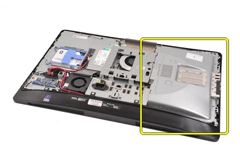
Press down on the release latch (1) where the cover attaches to the VESA mount. Pull the cover away to the right (2) of the chassis.

-
Complete.

-
Pre-Removal Instructions Before removing the Fan Duct:
-
During installation or removals of any hardware always ensure that all data is backed up properly.
-
Disconnect any telephone, network, or USB cables from the computer.
-
Disconnect the computer and all attached devices from their electrical outlets.
-
Remove the System Stand, the Rear Cover, and the System Board Cover.
-
-
Establishing image.

-
Remove one screw from the duct.

-
Gently lift the duct out of the computer.

-
Complete.

-
Pre-Removal Instructions Before removing the VESA Mount Cover:
-
During installation or removals of any hardware always ensure that all data is backed up properly.
-
Disconnect any telephone, network, or USB cables from the computer.
-
Disconnect the computer and all attached devices from their electrical outlets.
-
Remove the System Stand, the Rear Cover, and the System Board Cover.
-
-
Establishing image.

-
Remove the five (5) screws securing the VESA mount cover to the computer.

-
Gently remove the VESA mount cover from the computer.

-
Complete.

-
Pre-Removal Instructions Before removing the Memory Cover:
-
During installation or removals of any hardware always ensure that all data is backed up properly.
-
Disconnect any telephone, network, or USB cables from the computer.
-
Disconnect the computer and all attached devices from their electrical outlets.
-
Remove the System Stand, and Rear Cover.
-
-
Establishing image.

-
Lift and remove the cover.

-
Complete.

-
Pre-Removal Instructions Before removing the Memory:
-
During installation or removals of any hardware always ensure that all data is backed up properly.
-
Disconnect any telephone, network, or USB cables from the computer.
-
Disconnect the computer and all attached devices from their electrical outlets.
-
Remove the System Stand, Rear Cover, and the Memory Cover.
-
-
Establishing image.
-
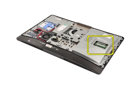
Pull the pins at either side away from each other, to release the memory.

-
Remove the memory.

Note: Repeat steps 3 and 4 for any additional Dual Inline memory module (DIMM)s that are installed.
-
Complete.

-
Pre-Removal Instructions Before removing the Optical Drive (CD-ROM, DVD):
-
During installation or removals of any hardware always ensure that all data is backed up properly.
-
Disconnect any telephone, network, or USB cables from the computer.
-
Disconnect the computer and all attached devices from their electrical outlets.
-
Remove the System Stand, and Rear Cover.
-
-
Establishing image.
-
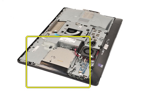
Press the release latch (1) at the rear of the drive and pull the drive out of the chassis (2).

-
Remove the two (2) screws from the latch on the back of the drive and remove the latch from the drive.

-
Complete.

-
Pre-Removal Instructions Before removing the Converter Board:
-
During installation or removals of any hardware always ensure that all data is backed up properly.
-
Disconnect any telephone, network, or USB cables from the computer.
-
Disconnect the computer and all attached devices from their electrical outlets.
-
Remove the System Stand, and Rear Cover.
-
-
Establishing image.

-
Remove the two (2) cables from the converter board.

-
Remove the two (2) screws securing the converter board to the computer.

-
Gently remove the converter board from the computer.

-
Complete.

-
Pre-Removal Instructions Before removing the Hard Disk Drive (HDD):
-
During installation or removals of any hardware always ensure that all data is backed up properly.
-
Disconnect any telephone, network, or USB cables from the computer.
-
Disconnect the computer and all attached devices from their electrical outlets.
-
Remove the System Stand, Rear Cover, and System Board Cover.
-
-
Establishing image.

-
The primary hard drive is on the right-hand side of the computer below the Memory. Press down on the plastic tab (1) and then pull the hard drive out to the right of the chassis to remove it.

-
The secondary hard drive is on the left-hand side of the computer above the Converter board. Press down on the plastic tab (1) and then pull the hard drive out to the left of the chassis to remove it.

-
Remove the plastic strips from both sides of the hard drive.

-
Complete.

Additional Information
| If you require further assistance, contact technical Support. |
| Contact Us |
Article Properties
Affected Product
OptiPlex 9030 All-In-One
Last Published Date
09 Jan 2023
Version
6
Article Type
Solution