Latitude 7380: Customer Replaceable Unit (CRU) part removal guide
Summary: This article is a guide to safe removal and replacement of those parts of a Latitude 7380 notebook that Dell considers safe and easy for anyone to attempt.
This article applies to
This article does not apply to
This article is not tied to any specific product.
Not all product versions are identified in this article.
Symptoms
These guides will take you step by step through the safe removal of what are considered to be the Customer Replaceable Unit (CRU) parts of a Latitude 7380 system. (CRUs are the parts of the system that shouldn't need an engineer to remove or replace.) The guides will also include pictures to reference what's involved.
Table of Contents:
Removal Guide
If these guides do not cover what you are looking to do, then you will want to reference your System Manual.
The article below provides information on safe practises to take into consideration before working with electrical equipment.
Cause
Removal Instructions
 Note: Please click on the title of the section you want to open below, in order to see the contents.
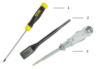
| 1 | Small Phillip's head screwdriver | 2 | Plastic Scribe |
| 3 | Small Flat head screwdriver |
 Note: Be aware that using a large Phillips or Flat Head screwdriver may result in damage to the head of the screws. This would make their removal impossible without speciality tools, that aren't available to our onsite engineers.
-
Pre-Removal Instructions Before removing the Main Access Panel:
-
During installation or removal of any hardware always ensure all data is backed up properly
-
Disconnect any telephone, network, or USB cables from the computer
-
Disconnect the computer and all attached devices from their electrical outlets
-
-
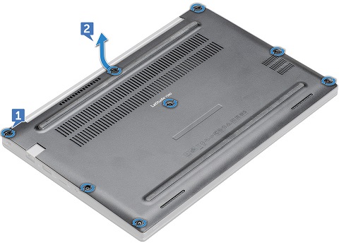
Turn your system onto it's lid and release the eight (8) captive screws that secure the base to the chassis [1].
-
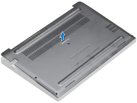
Use a plastic scribe to pry the base cover starting from the hinges to the top edge of the cover [2] and lift it from the PC.
-
Pre-Removal Instructions Before removing the SD Micro Memory Card:
-
During installation or removal of any hardware always ensure all data is backed up properly
-
Disconnect any telephone, network, or USB cables from the computer
-
Disconnect the computer and all attached devices from their electrical outlets
-
-
Press in on the Micro SD Card and then release to have it pop out of the slot.
-
Pull the Micro SD Card out of the computer.
-
Pre-Removal Instructions Before removing the Memory:
-
During installation or removal of any hardware always ensure all data is backed up properly
-
Disconnect any telephone, network, or USB cables from the computer
-
Disconnect the computer and all attached devices from their electrical outlets
-
Please remove the Base Cover and Micro SD Card
-
-
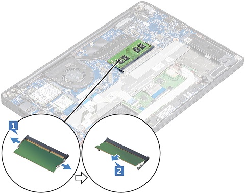
Pull the securing clips away from the memory module until it pops up [1], remove the memory module from the slot [2].
-
Pre-Removal Instructions Before removing the PCIe Solid State Drive (SSD):
-
During installation or removal of any hardware always ensure all data is backed up properly
-
Disconnect any telephone, network, or USB cables from the computer
-
Disconnect the computer and all attached devices from their electrical outlets
-
Please remove the Base Cover, and Micro SD Card
-
-
Remove the two (2) screws that secure the SSD thermal bracket [1], then lift the bracket off of the SDD card [2].
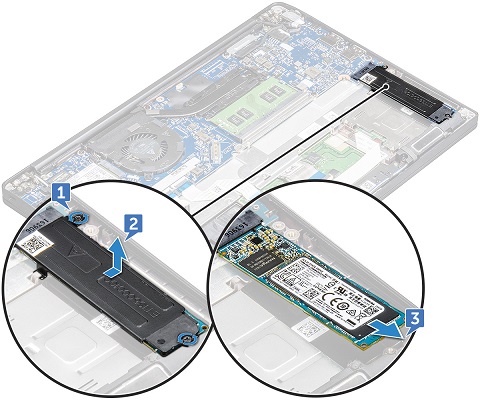
-
Slide the SSD card towards the front of the system and remove it from the system [3].
-
Pre-Removal Instructions Before removing the SATA Solid State Drive (SSD):
-
During installation or removal of any hardware always ensure all data is backed up properly
-
Disconnect any telephone, network, or USB cables from the computer
-
Disconnect the computer and all attached devices from their electrical outlets
-
Please remove the Base Cover, and Micro SD Card
-
-
Remove the screw that holds the SSD card down [1].
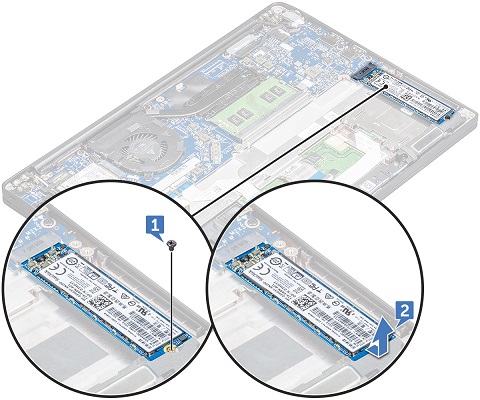
-
Slide the SSD card towards the front of the system and remove it from the system [2].
-
Pre-Removal Instructions Before removing the SIM Card:
-
During installation or removal of any hardware always ensure all data is backed up properly
-
Disconnect any telephone, network, or USB cables from the computer
-
Disconnect the computer and all attached devices from their electrical outlets
-
-
Insert a straightened paperclip or micro SIM card removal tool into the pinhole on the SIM card tray [1].
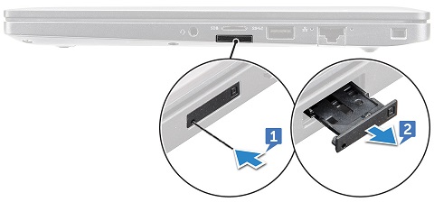
-
Use a plastic scribe to pull the SIM card tray out [2].
-
If a SIM is installed you can pull it out of the SIM tray.
-
Pre-Removal Instructions Before removing the WWAN Card (3G, Cellular):
-
During installation or removal of any hardware always ensure all data is backed up properly
-
Disconnect any telephone, network, or USB cables from the computer
-
Disconnect the computer and all attached devices from their electrical outlets
-
Please remove the Base Cover, and Micro SD Card
-
-
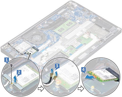
Remove the screw that secures the metal bracket to the WWAN card [1] and remove the bracket [2].
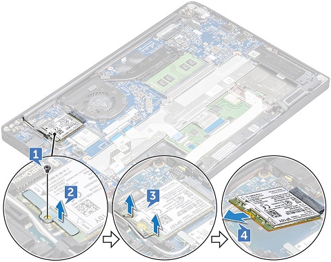
-
Disconnect the WWAN antenna cables from the connectors on the WWAN card [3].
-
Lift the WWAN card out of the system [4].
-
Pre-Removal Instructions Before removing the WLAN Card (WiFi, Wireless):
-
During installation or removal of any hardware always ensure all data is backed up properly
-
Disconnect any telephone, network, or USB cables from the computer
-
Disconnect the computer and all attached devices from their electrical outlets
-
Please remove the Base Cover, and Micro SD Card
-
-
Remove the screw that secures the metal bracket to the WLAN card [1] and remove it [2].
-
Disconnect the WLAN antenna cables from the connectors on the WLAN card [3].
-
Left the card out of the system [4].
Resolution
| If you require further assistance, contact technical Support. | ||
| Contact Us | ||
Affected Products
Latitude 7380Article Properties
Article Number: 000140702
Article Type: Solution
Last Modified: 01 May 2026
Version: 6
Find answers to your questions from other Dell users
Support Services
Check if your device is covered by Support Services.