PowerFlex Manager 5.0: Procedure on How to Replace Storage Node
Summary: This article provides the procedure on how to replace the Storage node using PowerFlex Manager.
Instructions
If the PowerFlex cluster has five nodes and a node needs replacement, follow the steps outlined in this article.
How to Replace a healthy PowerFlex Storage Only node using PowerFlex Manager.
To remove a node from a 5-node PowerFlex cluster, first add another node to maintain cluster integrity, and ensure that sufficient space exists in the rack for installing a new node.
Prerequisites
The PowerFlex storage-only node must be in a healthy state to perform the following procedure.
Steps
- Place the new node in the rack
- Refer to the Cabling and Connectivity Guide and complete the power and networking cable connections.
- Go to the Resource group, click Add a node operation (requires new IP addresses set).
- Wait for rebalance to complete
- Log in to PowerFlex Manager.
- On Dashboard, in the Lifecycle tab, click Resource Groups.
- Select a resource group to which the node must be added.
- On the Resource Group Details Page, click Add Resources > Add Nodes
- On the Duplicate Node screen, select the Resource to Duplicate and Number of instances > Click Next, review the Additional Settings, and click Next
- Review the Summary and click Finish to add a new node.
- Temporarily reduce the spare node count from 1 to 0 to enable node removal. This does not put the system at risk since it is protected with Erasure Coding.
- Log in to the PowerFlex Manager UI.
- Go to Storage System > select Device Group.
- From the More Actions drop-down menu, select Spare capacity.
- Select Spare Node and update the value from 1 to 0.
- Click Apply.
- On Dashboard, in the Lifecycle tab, click Resource Groups.
- Select a resource group from which the node has to be removed.
- On the Resource Group Details page, click More Actions > Remove Resource.
- Select the node on the Node Lists page and click Next.
- Select the resource to delete. Verify the iDRAC IP address and select the radio button in the left column. After selecting the correct node, click Next.
- From the Resource removal type, select:
- Delete Resource makes configuration changes to the nodes, switch ports, virtual machine managers, and PowerFlex to unconfigure those components. Also, it returns the components to the available inventory.
NOTE: Unless otherwise instructed, select Delete Resource for all instances of node replacement.
- Remove Resource removes deployment information but does not make any configuration changes to the nodes, switch ports, virtual machine managers, and PowerFlex. Also, it returns the components to the available inventory.
- Select Delete Resource, perform the following steps:
- From the Resource removal type, select Delete resource.
- Type DELETE RESOURCE and click Remove.
PowerFlex Manager handles MDM role adjustments automatically. - Monitor the removal of the node on the Recent Activity Log window. The Jobs-in-progress status indicates one job running at the top of the window.
- After the job is completed, confirm that the PowerFlex node was successfully removed or deleted. You can visually confirm that the node has been removed or deleted as the Resource Group displays one less node. You should not see any fail, error, or unsuccessful message in the activity log. A failure indicates that a PowerFlex node was not removed completely, or the removal process failed.
- . Remove Resource from the resource inventory page.
- Physically remove the additional Storage Node from the Rack.
- Increase the spare node from 0 to 1.
-
- Log in to the PowerFlex Manager
- Go to Storage System > select Device Group.
- From the More Actions menu, select Spare capacity.
- Select Spare node and update the value from 0 to 1.
- Click Apply
How to Replace a faulty PowerFlex Storage Only node using PowerFlex Manager.
To remove a node from a 5-node PowerFlex cluster, first add another node to maintain cluster integrity, and ensure that sufficient space exists in the rack for installing a new node.
Prerequisites
The PowerFlex storage only node must be in a faulty state.
- Place the new node in the rack
- Refer to the Cabling and Connectivity Guide and complete the power and networking cable connections
Note: For Replacing the node, refer to the Hardware replacement procedure from the Full Node FRU document.
- Log in to PowerFlex Manager.
- On Dashboard, in the Lifecycle tab, click Resource Groups.
- Select a resource group from which the node has to be removed.
- On the Resource Group Details page, click More Actions > Remove Resource.
- Select the faulty node on the Node Lists page and click Next.
- Select the resource to remove. Verify the iDRAC IP address, and select the radio button in the left column. After selecting the correct node, click Next.
- From the Resource removal type, select Remove Resource
- From the Remove Resource Window, perform the following steps:
- From the Remove Resource Window, perform the following steps:
- To keep the node in the inventory, select Leave resource in the PowerFlex Manager inventory and set state to and select the state:
- From the Remove Resource Window, perform the following steps:
Managed
Unmanaged
Reserved
- To remove the node:
-
-
- Select Remove resource from the PowerFlex Manager inventory.
- Click Remove.
- Monitor the removal of the node on the Recent Activity Log window.
- The Jobs in-Progress status indicates one job running at the top of the window.
- After the job is completed, confirm that the PowerFlex node was successfully removed from the resource group. Visually confirm that the node has been removed as the Resource Group displays one less node as shown below. You should not see any fail, error, or unsuccessful message in the activity log.
- A failure indicates that a PowerFlex node was not removed completely, or the removal process failed
- If the failed node belongs to the MDM cluster, use SCLI to switch the cluster mode from 5-node to 3-node by removing the failed secondary MDM or tiebreaker. Otherwise, you cannot remove the node since the MDM remains in a degraded state
- See the following example command:
-
scli --switch_cluster_mode --cluster_mode 3_node -- remove_secondary_mdm_id 0x311b46bc5eecce01 --remove_tb_id 0x5b3f599d4df98405 Once the MDM cluster is converted to 3-node, remove standby MDM role from the failed node. The following example shows the command:
scli --remove_standby_mdm --remove_mdm_id 0x5b3f599d4df98405
How Add the replacement storage-only node using PowerFlex Manager.
Use the below procedure for replacing the failed node, requires new IP addresses set.
Steps
- Log in to the jump server.
- Log in to PowerFlex Manager.
-
- Ensure that no other jobs are in progress.
- Ensure that you have proper network connectivity.
- In PowerFlex Manager, click Resources.
- In the upper-right of the Resources page, click Discover Resources.
-
- Click Next from the Welcome page.
- Click Add Resource Type from the Identify Resources page.
- Select Node (Hardware/Software Management), from Resource Type.
- Enter the iDRAC IP address, select Managed, select the recorded Node Pool, select the appropriate iDRAC credential, and click Next.
- Review the Summary page and click Finish > Yes.
- Monitor the jobs in progress either from the Dashboard Activity Log or you can click Jobs In-Progress > View Jobs Page, where you can see the list of the running jobs. The Discovery Job Running can take a few minutes. Refresh the Dashboard Activity Log page until the job is complete.
- The node count on the Dashboard page should increase to the original level, and the node is displayed in the resources list. Click the Resources link at the top of the page to view the resource list. The node now appears in the list with the same iDRAC IP address and is not in the Not in Use deployment state.
- Ensure that the node is in the appropriate Node Pool on the Resources page. If necessary, select the node pool, click Edit, and add the new node.
- The node is ready to be added to a PowerFlex rack or PowerFlex appliance.
- Click Lifecycle > Resource Groups.
- Select the resource group that was recorded earlier.
- Under Resource Group Details, click Add Resources and select Add Nodes from the drop-down list.
- Select the resource to duplicate. Any node in the list can be used for resource duplication. The configuration of the existing PowerFlex nodes is applied to the new PowerFlex nodes. Select the number of instances as 1 and click Next.
- Review the Duplicate Node page. Expand OS Settings. If the Host Name Selection is set to Reverse DNS Lookup, there are no modifications that are required on this page. Click Next to continue.
-
- If the Host Name Selection is not set to Reverse DNS Lookup, for the Host Name Selection field, select Specify at Deployment time and for the Host Name field enter the hostname that was recorded in the information gathering table.
- Set the component name to the original hostname.
- Select IP Source as User Entered IP.
- Set only the first IP address in the list, which is PowerFlex Management IP Source (for Storage-Only) to the defective nodes OS IP recorded earlier.
- Click Next, verify the node settings, and click Finish.
The deployment begins, and it is in the In-Progress state. Monitor the Recent Activity log. The activity log output may vary depending on the node type and node firmware state.
The firmware is updated for the node that is not compliant with the RCM or IC, as defined in PowerFlex Manager.
This can take two hours to deploy. Times can vary depending on many factors. PowerFlex Manager updates the firmware if required, configures switches, installs the nodes operating system and configures the PowerFlex rack with the new node.
- When the job is complete, confirm that the node was successfully deployed. Confirm that the node has been added as a resource group that displays one more node. You should not see any failed, error, or unsuccessful messages in the activity log. Any such failures indicate incomplete or failed deployment.
NOTE: If deployment fails or is incomplete, verify that there are no connectivity issues including the NIC cabling.
- You must increase the spare node to 1 node.
-
- Log in to the PowerFlex Manager
- Go to Storage System > Select Device Group.
- From the More Actions menu, select Spare capacity.
- Select Spare node and update the value from 0 to 1.
- Click Apply.
- After adding the PowerFlex node, change the cluster mode from 3 to 5 using the following:
-
- Log in to the primary MDM. If you are replacing TB and the node is added as a Standby MDM with a manager role, use the following steps. Otherwise skip these steps.
- Edit vi.opt/emc/scaleio/mdm/cfg/conf.txt
- Change the manager role from 1 to 0 and click Save.
- Remove the newly added node from standby MDM. See the following example of the command scli --remove_standby_mdm --remove_mdm_id 0x5b3f599d4df98405
- Update the new node as TB.
- Change the cluster mode from 3 to 5.
See the following example of the command:
scli --switch_cluster_mode --cluster_mode 5_node --add_secondary_mdm_id 0x7b25db9b6a8b3800 --add_tb_id 0x101e8fec38b0240
- If you have a failure and know the cause, fix the issue and retry the deployment. If there are no errors, the procedure is complete.
- If CloudLink is not deployed in the system, skip the below step.
- If CloudLink is deployed on the system, log in to CloudLink Center. Verify that the machine status displays Connected and the drives are encrypted
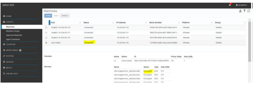
For the environment with CloudLink self-encrypting drives (SEDs), verify that the disk is visible in the CloudLink Center and shows as Encrypted HW and Managed for SED devices.

During the replacement procedure, If the SED gets locked, contact Dell Technologies Support.
Remove storage node from PowerFlex cluster.
Use the procedure to remove storage node from the PowerFlex cluster.
- Log in to the PowerFlex manager
- Temporarily reduce the spare node count from 1 to 0 to enable node removal. This does not put the system at risk since it is double protected with Erasure Coding.
- Go to Block >Storage System > Select Device Group.
- From the More Actions, drop down menu select Spare capacity.
- Select Spare Node and update value from 1 to 0.
- Click Apply.
- Remove the Storage Node from the PowerFlex cluster
- From PowerFlex manager UI, Go to Lifecycle > Storage Node
- Select the node from the list
More Actions > Remove Storage Node.
- In the Remove Storage Node Window Type REMOVE STORAGE NODE, Click Remove
- Remove the Storage Data Target (SDT) from the PowerFlex cluster (if applicable)
- From PowerFlex manager UI, Go to Block > Storage System > NVMe Targets
- Select the node from the list and Click Remove
- Physically remove the PowerFlex node from the rack, refer the Full node FRU document for the procedure
- Increase the spare Node to 1.
Go to Block >Storage System > Select Device Group.
- From the More Actions, drop down menu select Spare capacity.
- Select Spare Node and update value from 0 to 1.
- Click Apply
- Update the resource group details
Click Lifecycle > Resource Group > Select the resource group > More options select Update Resource Group details.
- Review the OS Credentials page, and click Next
- Review the Inventory Summary page, and click Next
- Review the Summary page, and click Finish
- Remove Resource from the resource inventory page.
- On the Resources page, click the All Resources tab
- From the list of resources, select one or more resources, and click Remove
- Click OK when the confirmation message appears