Dell EMC Networking - Adding a VxRail Node to SmartFabric Cluster, New Node may not be Added to VM Guest Networks Automatically
Summary: While adding a VxRail node to an existing cluster with SmartFabric Services (SFS) enabled on the Leaf and or Top of Rack (ToR) switches. The Node should automatically be added to all networks in the cluster. However, in some cases, the new VxRail node is not added to the VM Guest networks. ...
This article applies to
This article does not apply to
This article is not tied to any specific product.
Not all product versions are identified in this article.
Instructions
NOTE: This issue is found on deployments with VxRail 7.0.202 and OS10.5.2.7.
Example
Existing VxRail Cluster Configuration
A VxRail cluster was deployed with SmartFabric Services that are enabled on the switches. The networks that are configured during deployment were External Management (VLAN 1811), vMotion (VLAN 1812), vSAN (VLAN 1813), and one or more VM Guest Networks. In this example, two VM Guest networks were specified during VxRail deployment (VLANs 1814 and 1815), as shown in the figure below.
NOTE: VLAN IDs used are examples only.
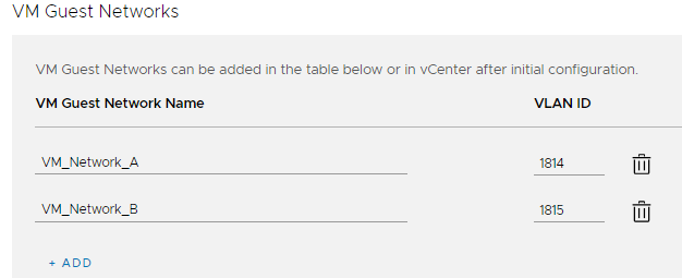
Figure 1 VM Guest Networks Specified During Deployment
The cluster was deployed successfully. All switch ports connected to VxRail nodes in the cluster were successfully added to all networks specified during VxRail deployment.
Figure 1 VM Guest Networks Specified During Deployment
The cluster was deployed successfully. All switch ports connected to VxRail nodes in the cluster were successfully added to all networks specified during VxRail deployment.
Issue when adding a VxRail node to the existing cluster
A new VxRail node is added to the VxRail cluster using the Add VxRail Hosts wizard in the vSphere Client. In this example, the existing VxRail nodes are connected to Ethernet 1/1/1-1/1/3 on both leaf switches. The new VxRail node is connected to Ethernet 1/1/4 on both leaf switches. If the issue occurs, the ports for the new VxRail node are not automatically added to the VM Guest networks, 1814 and 1815, on the two leaf switches. The show virtual-network command output appears as follows:
NOTE: The following output is from the first leaf switch in the rack, Leaf1A. The output for the second leaf switch in the rack, Leaf1B, is the same.
In the output above, Ethernet 1/1/4 has not been added to the VM Guest networks, 1814 and 1815.

Figure 2 Server Interface Profile List in OMNI

Figure 3 Edit Networks
Leaf1A# show virtual-network
Codes: DP - MAC-learn Dataplane, CP - MAC-learn Controlplane, UUD - Unknown-Unicast-Drop
Un-tagged VLAN: 4080
Virtual Network: 1811
   VLTi-VLAN: 1811
   Members:
      VLAN 1811: port-channel1000, ethernet1/1/1, ethernet1/1/2, ethernet1/1/3, ethernet1/1/4
   VxLAN Virtual Network Identifier: 1811
      Source Interface: loopback2(172.30.0.0)
      Remote-VTEPs (flood-list):

Virtual Network: 1812
   VLTi-VLAN: 1812
   Members:
      VLAN 1812: port-channel1000, ethernet1/1/1, ethernet1/1/2, ethernet1/1/3, ethernet1/1/4
   VxLAN Virtual Network Identifier: 1812
      Source Interface: loopback2(172.30.0.0)
      Remote-VTEPs (flood-list):

Virtual Network: 1813
   VLTi-VLAN: 1813
   Members:
      VLAN 1813: port-channel1000, ethernet1/1/1, ethernet1/1/2, ethernet1/1/3, ethernet1/1/4
   VxLAN Virtual Network Identifier: 1813
      Source Interface: loopback2(172.30.0.0)
      Remote-VTEPs (flood-list):

Virtual Network: 1814
   VLTi-VLAN: 1814
   Members:
      VLAN 1814: port-channel1000, ethernet1/1/1, ethernet1/1/2, ethernet1/1/3
   VxLAN Virtual Network Identifier: 1814
      Source Interface: loopback2(172.30.0.0)
      Remote-VTEPs (flood-list):

Virtual Network: 1815
   VLTi-VLAN: 1815
   Members:
      VLAN 1815: port-channel1000, ethernet1/1/1, ethernet1/1/2, ethernet1/1/3
   VxLAN Virtual Network Identifier: 1815
      Source Interface: loopback2(172.30.0.0)
      Remote-VTEPs (flood-list):

Virtual Network: 3939
   Description: In-band SmartFabric Services discovery network
   VLTi-VLAN: 3939
   Members:
      VLAN 3939: port-channel1000, ethernet1/1/1, ethernet1/1/2, ethernet1/1/3, ethernet1/1/4
   VxLAN Virtual Network Identifier: 3939
      Source Interface: loopback2(172.30.0.0)
      Remote-VTEPs (flood-list):

Virtual Network: 4091
   Description: Default untagged network for client onboarding
   VLTi-VLAN: 4091
   Members:
      Untagged: ethernet1/1/1, ethernet1/1/2, ethernet1/1/3, ethernet1/1/4
      VLAN 4091: port-channel1000
   VxLAN Virtual Network Identifier: 4091
      Source Interface: loopback2(172.30.0.0)
      Remote-VTEPs (flood-list):
In the output above, Ethernet 1/1/4 has not been added to the VM Guest networks, 1814 and 1815.
Workaround
If the issue occurs, the switch ports for one or more newly added VxRail hosts may be added to the VM Guest networks using OMNI.- Deploy OMNI 2.1 and add the SmartFabric per the OpenManage Network Integration for SmartFabric Services User Guide, Release 2.1. This guide is available on the Dell EMC OpenManage Network Integration for VMware vCenter website.
- Determine the MAC addresses of the ports connected to the new VxRail node by running show LLDP neighbors at the CLI of each leaf switch. The ports for the new node in this example are ethernet1/1/4 on each leaf switch. The output shows that the MAC addresses are 98:03:9b:0f:83:7a and 98:03:9b:0f:83:7b.
Leaf1A# show lldp neighbors | grep vmnic
ethernet1/1/1       c1-vxrail-03.dell... 1c:34:da:55:f3:5c             vmnic0
ethernet1/1/2       c1-vxrail-02.dell... 98:03:9b:0f:84:aa             vmnic0
ethernet1/1/3       c1-vxrail-01.dell... 1c:34:da:55:f3:4c             vmnic0
ethernet1/1/4       c1-vxrail-04.dell... 98:03:9b:0f:83:7a             vmnic0

Leaf1B# show lldp neighbors | grep vmnic
ethernet1/1/1       c1-vxrail-03.dell... 1c:34:da:55:f3:5d             vmnic1
ethernet1/1/2       c1-vxrail-02.dell... 98:03:9b:0f:84:ab             vmnic1
ethernet1/1/3       c1-vxrail-01.dell... 1c:34:da:55:f3:4d             vmnic1
ethernet1/1/4       c1-vxrail-04.dell... 98:03:9b:0f:83:7b             vmnic1
- In OMNI, select the SmartFabric instance in the left pane. In the right pane, select the Server Interface tab. The Server Interface Profile list displays as shown.
Figure 2 Server Interface Profile List in OMNI
- Select the radio button next to the first MAC address of the new VxRail node, and click EDIT NETWORKS, as shown.
Figure 3 Edit Networks
- The Edit Server Interface Profile Networks window displays. Next to Tagged Networks, click the
 icon and select the checkbox next to each of the VM Guest networks. For this example, VLANs 1814 and 1815 are selected, as shown.
NOTE: Be sure to leave any existing networks (vMotion, vSAN, so on) selected.
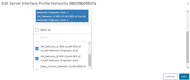
Figure 4 VM Guest Networks Selected
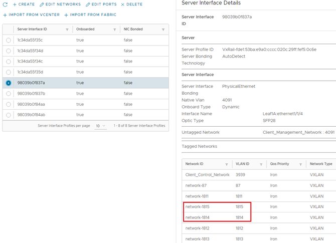
Figure 5 Server Interface Added to VM Guest Networks 1814 and 1815
Figure 4 VM Guest Networks Selected
- Click EDIT to apply the settings.
- Verify that the settings have been applied correctly. Select the radio button next to the MAC address, and view the network list in the Server Interface Details pane, as shown.
Figure 5 Server Interface Added to VM Guest Networks 1814 and 1815
NOTE: The show virtual-network command may also be used at the leaf switch CLI to verify that the interfaces are in the correct networks.
- Repeat steps 4-7 above for the remaining interfaces.
Affected Products
PowerSwitch S4112F-ON/S4112T-ON, PowerSwitch S4128F-ON/S4128T-ON, PowerSwitch S4148F-ON/S4148T-ON/S4148FE-ON, PowerSwitch S5212F-ON, PowerSwitch S5224F-ON, PowerSwitch S5232F-ON, PowerSwitch S5248F-ON, PowerSwitch S5296F-ONArticle Properties
Article Number: 000191201
Article Type: How To
Last Modified: 05 Jun 2025
Version: 4
Find answers to your questions from other Dell users
Support Services
Check if your device is covered by Support Services.