Latitude 5500 Teardown/Removal guide for customer replaceable units (CRUs)
Summary: This article is a guide to safe removal and replacement of those parts of a Latitude 5500 notebook that Dell considers safe and easy for anyone to attempt.
This article applies to
This article does not apply to
This article is not tied to any specific product.
Not all product versions are identified in this article.
Symptoms
These guides will take you step by step through the safe removal of what are considered to be the Customer Replaceable Unit (CRU) parts of a Latitude 5500 Notebook system. (CRUs are the parts of the system that shouldn't need an engineer to remove or replace.) The guides will also include pictures to reference what's involved.
Table of Contents:
Removal Guide
If these guides do not cover what you are looking to do, then you will want to reference your system manual.
The article below provides information on safe practises you should be taking into consideration before working with electrical equipment.
Removal Instructions
 Note: Please click on the title of the section you want to open below, to see the contents.
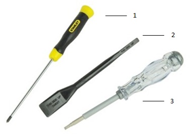
| 1 | Small Phillip's head screwdriver | 2 | Plastic Scribe |
| 3 | Small Flathead screwdriver |
 Note: Be aware that using a large Phillips or Flat Head screwdriver may result in damage to the head of the screws. This would make their removal impossible without speciality tools, that aren't available to our onsite engineers.
-
Pre-Removal Instructions Before removing the Bottom Cover:
-
During installation or removal of any hardware always ensure all data is backed up properly
-
Disconnect any telephone, network, or USB cables from the computer
-
Disconnect the computer and all attached devices from their electrical outlets
-
-
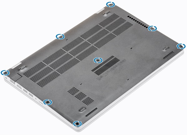
Loosen the eight (8) captive screws along the back hinge edge and at either side of the middle and front of the base plastics.
-
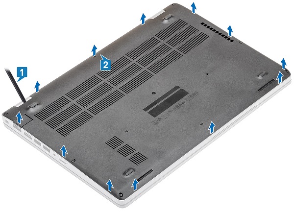
Using a plastic scribe or similar device, pry along the base cover from the top left corner and work your way around
-
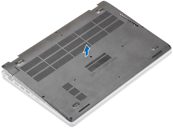
Lift the base cover up and off of the system
-
Pre-Removal Instructions Before removing the Battery:
-
During installation or removal of any hardware always ensure all data is backed up properly
-
Disconnect any telephone, network, or USB cables from the computer
-
Disconnect the computer and all attached devices from their electrical outlets
-
Please remove the Access Panel
-
-
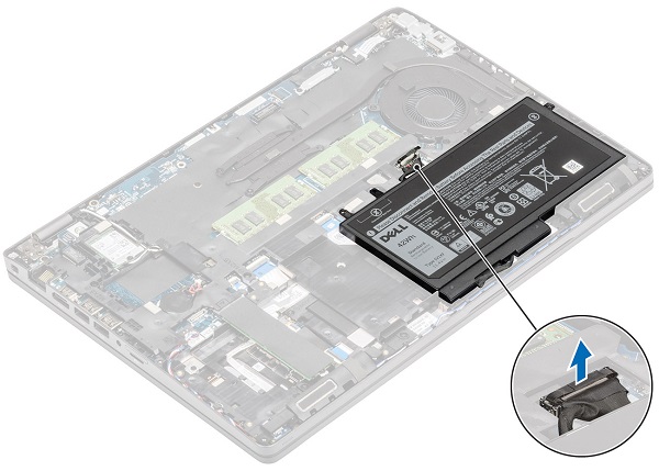
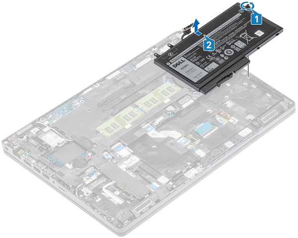
Disconnect the battery cable from the motherboard
-
Loosen the single captive screw that secures the battery to the palmrest and slide the battery towards the rear of the PC until you can lift it out of the system
-
Pre-Removal Instructions Before removing the MicroSD Card:
-
During installation or removal of any hardware always ensure all data is backed up properly
-
Disconnect any telephone, network, or USB cables from the computer
-
Disconnect the computer and all attached devices from their electrical outlets
-
-
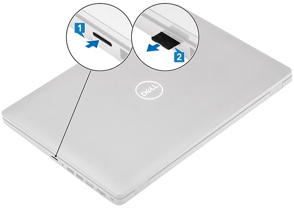
Push the seated microSD card further into the reader [1], it will pop out far enough for you to get a grip of it
-
Pull the microSD card fully out of the slot and system [2]
-
Pre-Removal Instructions Before removing the Memory:
-
During installation or removal of any hardware always ensure all data is backed up properly
-
Disconnect any telephone, network, or USB cables from the computer
-
Disconnect the computer and all attached devices from their electrical outlets
-
Please remove the System Cover and Battery
-
-
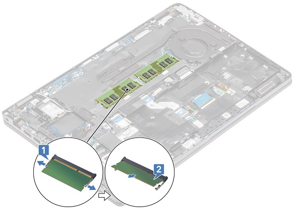
The memory is in the middle of the system, pull the metal securing clips apart to release the memory DIMM
-
The DIMM pops up at an angle, lift it up and out of the system
 Note: This system can accommodate two memory DIMMs, repeat the steps for any additional memory in the system.
-
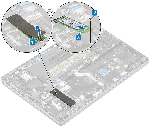
Pre-Removal Instructions Before removing the M.2 Solid State Drive (SSD):
-
During installation or removal of any hardware always ensure all data is backed up properly
-
Disconnect any telephone, network, or USB cables from the computer
-
Disconnect the computer and all attached devices from their electrical outlets
-
Please remove the System Cover and Battery
-
-
The SSD card sits in the bottom left-hand side of the system, Peel off the tape from the SSD and remove the single screw securing the end of the SSD to the motherboard
-
The card pops up at an angle, lift it up and out of the system
-
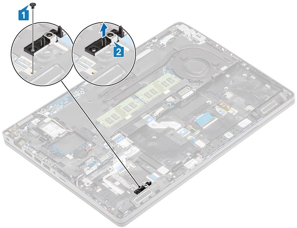
Remove the single screw that secures the SSD bracket to the palmrest and lift the bracket out of the slot in the palmrest
-
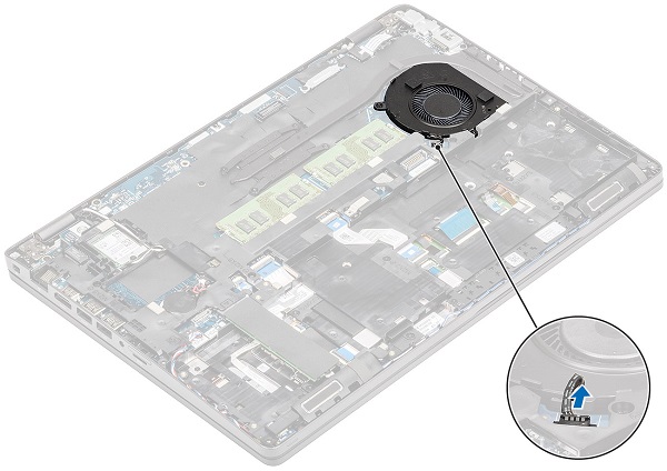
Pre-Removal Instructions Before removing the Fan:
-
During installation or removal of any hardware always ensure all data is backed up properly
-
Disconnect any telephone, network, or USB cables from the computer
-
Disconnect the computer and all attached devices from their electrical outlets
-
Please remove the System Cover and Battery
-
-
The system fan is located above the battery, disconnect the fan cable from the motherboard
-
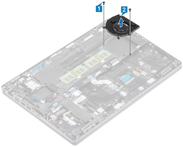
Remove the two (2) screws securing the fan to the palmrest and lift the fan out of the system
-
Pre-Removal Instructions Before removing the WWAN Card (Cellular, Wireless):
-
During installation or removal of any hardware always ensure all data is backed up properly
-
Disconnect any telephone, network, or USB cables from the computer
-
Disconnect the computer and all attached devices from their electrical outlets
-
Please remove the System Cover and Battery
-
-
Remove the screw and the bracket from the card
-
Disconnect the antenna cables from the card (The cables have a press-stud connector and pop off the stud with a little pressure.)
-
The card pops up at an angle, lift it out of the slot and remove it from the system
-
Pre-Removal Instructions Before removing the WLAN Card (WiFi, Wireless):
-
During installation or removal of any hardware always ensure all data is backed up properly
-
Disconnect any telephone, network, or USB cables from the computer
-
Disconnect the computer and all attached devices from their electrical outlets
-
Please remove the System Cover and Battery
-
-
The WLAN card is located the top left-hand corner of the system, remove the screw and the bracket from the card
-
Disconnect the antenna cables from the card (The cables have a press-stud connector and pop off the stud with a little pressure.)
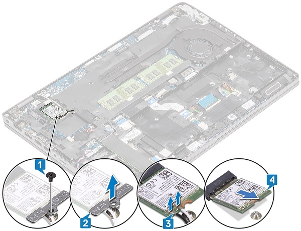
-
The card pops up at an angle, lift it out of the slot and remove it from the system
If you require further assistance, please contact Technical Support
| Contact Us |
Cause
N/A
Resolution
N/A
Affected Products
Latitude 5500Article Properties
Article Number: 000128140
Article Type: Solution
Last Modified: 05 May 2025
Version: 6
Find answers to your questions from other Dell users
Support Services
Check if your device is covered by Support Services.