Latitude 7410 Teardown, removal guide for customer replaceable units (CRUs)
Summary: This article is a guide to safe removal and replacement of those parts of a Latitude 7410 and 7410 2-in-1 notebook that Dell considers safe and easy for anyone to attempt.
This article applies to
This article does not apply to
This article is not tied to any specific product.
Not all product versions are identified in this article.
Symptoms
These guides take you step-by-step through the safe removal of the Customer Replaceable Unit (CRU) parts of a Latitude 7410 Notebook and 2-in-1 system. (CRUs are the parts of the system that should not need an engineer to remove or replace.) The guides include pictures to reference what is involved.
Table of Contents:
Removal Guide
If these guides do not cover what you are looking to do, then you will want to reference your System Manual.
The article below provides information about safe practices to take into consideration before working with electrical equipment.
Cause
N/A
Resolution
Removal Instructions
 Note: Click the title of the section you want to open below, in order to see the contents.
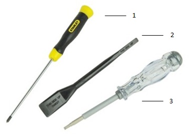
| 1 | Small Phillip's head screwdriver | 2 | Plastic Scribe |
| 3 | Small Flat head screwdriver |
 Note: Be aware that using a large Phillips or Flat Head screwdriver may result in damage to the head of the screws. This would make their removal impossible without specialty tools, that are not available to our onsite engineers.
-
Pre-Removal Instructions before removing the Access Panel:
-
During installation or removals of any hardware always ensure that all data is backed up properly
-
Disconnect any telephone, network, or USB cables from the computer
-
Disconnect the computer and all attached devices from their electrical outlets
-
-
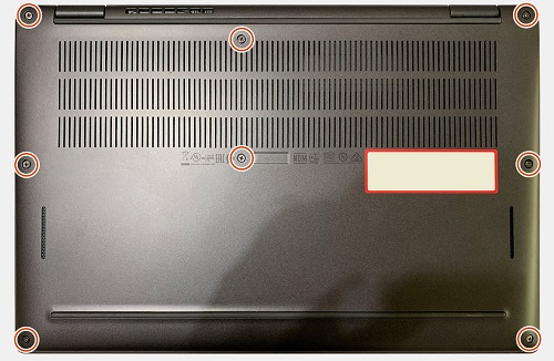
Turn the system over on its closed lid and loosen the eight (8) captive screws securing the access panel to the chassis
-
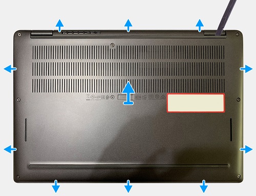
Using a plastic scribe or some other tool that will not mark the plastics, pry the cover up from the top left-hand side corner and work clockwise around the access panel to release it from the chassis
-
Lift the panel up and away from the chassis
 Caution: Do Not slide the scribe through the edge along the top side of the panel as it can damage the latches inside the Access Panel
Solid State Drive Removal
-
Pre-Removal Instructions before removing the Solid State Drive (SSD):
-
During installation or removals of any hardware always ensure that all data is backed up properly
-
Disconnect any telephone, network, or USB cables from the computer
-
Disconnect the computer and all attached devices from their electrical outlets
-
Please remove the Access Panel and disconnect the battery cable
-
-
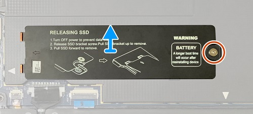
With the system on its closed lid, the SSD is located in the upper, center of the system.
-
Remove the single screw that secures the thermal plate and remove the thermal plate from on top of the SSD
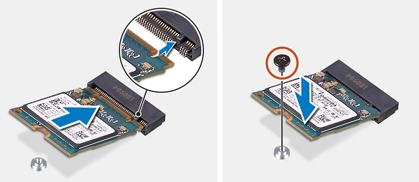
2230 SSD
-
Remove the single screw that secures the SSD to the chassis and lift it out of the M.2 connector and system
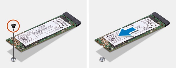
2280 SSD
-
Remove the single screw that secures the SSD to the chassis and lift it out of the M.2 connector and system
-
Pre-Removal Instructions before removing the MicroSD Memory Card:
-
During installation or removals of any hardware always ensure that all data is backed up properly
-
Disconnect any telephone, network, or USB cables from the computer
-
Disconnect the computer and all attached devices from their electrical outlets
-
-
The Micro SD slot is located on the left-hand edge of the system. Push in gently on the card in the slot and release to have it pop out of the slot
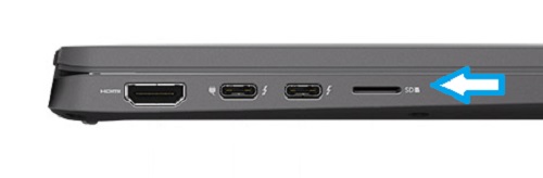
-
Grip the card and pull it the rest of the way out of the slot
-
Pre-Removal Instructions before removing the SIM Card:
-
During installation or removals of any hardware always ensure that all data is backed up properly
-
Disconnect any telephone, network, or USB cables from the computer
-
Disconnect the computer and all attached devices from their electrical outlets
-
-
The SIM slot is located on the right-hand edge of the system. Push a SIM card tool or a straightened paper clip gently into the hole on the left-hand side of the SIM card slot filler until it pops out of the slot
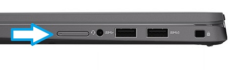
-
Remove the filler and fit the SIM card and push the filler back into the system until it locks in place
-
Pre-Removal Instructions before removing the WWAN Card (Cellular):
-
During installation or removals of any hardware always ensure that all data is backed up properly
-
Disconnect any telephone, network, or USB cables from the computer
-
Disconnect the computer and all attached devices from their electrical outlets
-
Please remove the Access Panel and disconnect the battery cable
-
-
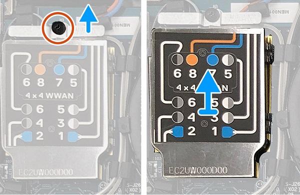
With the system on its closed lid, the WWAN card is located in the top left-hand corner of the system. Remove the single (1) screw that secures the WWAN shielding cover to the chassis
-
Using a plastic scribe, pry the shielding cover from on top of the antenna cables and the card will pop up at an angle from the motherboard
-
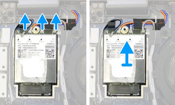
Disconnect the antenna cables pop connectors from the press studs on the WWAN card
-
Pull the card out of the connector on the motherboard and away from the system
-
Pre-Removal Instructions before disconnecting the WLAN Antennae (WiFi, Wireless):
-
During installation or removals of any hardware always ensure that all data is backed up properly
-
Disconnect any telephone, network, or USB cables from the computer
-
Disconnect the computer and all attached devices from their electrical outlets
-
Please remove the Access Panel and disconnect the battery cable
-
-
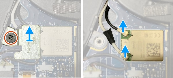
With the system on its closed lid, the WLAN module is located between the system fan and the SSD in the center of the system. Remove the single (1) screw that secures the WLAN antennae bracket to the chassis
-
Remove the bracket from on top of the antenna cables and disconnect the antenna cables pop connectors from the press studs on the WLAN module
If you require further assistance, please contact Technical Support.
| Contact Us |
Affected Products
Latitude 7410Article Properties
Article Number: 000128606
Article Type: Solution
Last Modified: 04 Jun 2025
Version: 6
Find answers to your questions from other Dell users
Support Services
Check if your device is covered by Support Services.