Dell OptiPlex 3040 Visual Guide
Summary: This article provides a Visual Guide for Dell OptiPlex 3040, Micro, SFF, and Mini Tower models.
This article applies to
This article does not apply to
This article is not tied to any specific product.
Not all product versions are identified in this article.
Instructions
Table of Contents:
- Micro Chassis (MFF) Front View
- Micro Chassis (MFF) Rear View
- Small Form Factor Chassis (SFF) Front View
- Small Form Factor Chassis (SFF) Rear View
- Mini-Tower Chassis (MT) Front View
- Mini-Tower Chassis (MT) Rear View
Note: For a more detailed description about each location, go to the system manuals at www.dell.com/support/manuals.
1. Micro Chassis (MFF) Front View
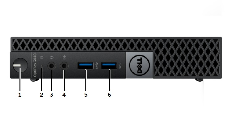
| 1 | Power Button, Power Light | 2 | Drive Activity Light |
| 3 | Universal Audio Jack Connector | 4 | Line-In Microphone Connector |
| 5 | USB 3.0 Connector | 6 | USB 3.0 Connector |
2. Micro Chassis (MFF) Rear View
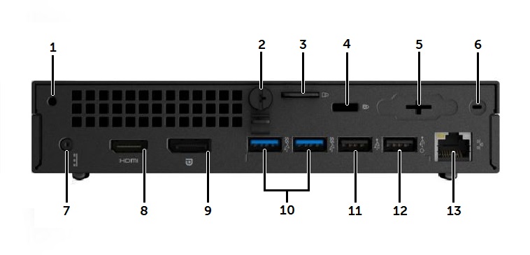
| 1 | Accessory Screw Hole | 2 | Cover Thumb Screw |
| 3 | Padlock Security Ring | 4 | Kensington Lock Slot |
| 5 | Optional VGA connector or I/O port | 6 | Wi-Fi Antenna SMA Connector location |
| 7 | DC-In Power Connector | 8 | HDMI Connector |
| 9 | DisplayPort Connector | 10 | USB 3.0 Connectors (x2) |
| 11 | USB 2.0 Connector | 12 | USB 2.0 Connector with Wake function |
| 13 | RJ45 Network Connector |
3. Small Form Factor Chassis (SFF) Front View
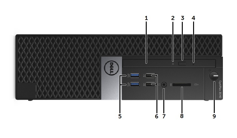
| 1 | Optical Drive | 2 | Optical Drive LED |
| 3 | Optical Drive Eject Button | 4 | Optical Drive Emergency Eject Pin Hole |
| 5 | USB 3.0 Connector (x2) | 6 | USB 2.0 Connector (x2) |
| 7 | Headphone/Mic Combo Connector | 8 | SD Card Slot |
| 9 | Power Button, Power Light |
4. Small Form Factor Chassis (SFF) Rear View
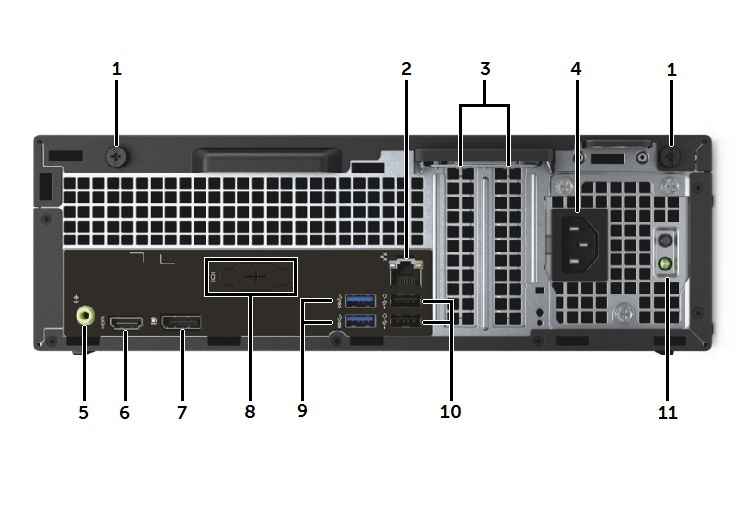
| 1 | Cover Release Thumb Screws | 2 | RJ45 Network Connector |
| 3 | Expansion Slots (x2) | 4 | AC Power Connector |
| 5 | Audio Out Connector | 6 | HDMI Connector |
| 7 | DisplayPort Connector | 8 | Optional VGA Connector or I/O Port |
| 9 | USB 3.0 Connectors (x2) | 10 | USB 2.0 Connectors (x2) with Wake function |
| 11 | Power Supply Test Button and LED |
5. Mini-Tower Chassis (MT) Front View
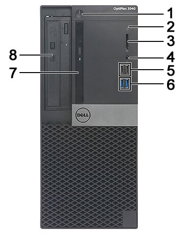
| 1 | Power Button and Power LED | 2 | Hard Drive Activity LED |
| 3 | SD Card Slot | 4 | Combo Audio Connector |
| 5 | USB 2.0 Connectors (x2) | 6 | USB 3.0 Connectors (x2) |
| 7 | Slim Type Drive Bay (optional) | 8 | 5.25 inch Drive Bay (optional) |
6. Mini-Tower Chassis (MT) Rear View
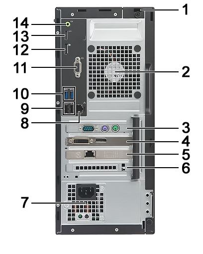
| 1 | Kensington Lock Slot | 2 | System Fan |
| 3 | PCIe x1 Expansion Board Slot | 4 | PCIe x16 Expansion Board Slot |
| 5 | PCIe x1 Expansion Board Slot | 6 | PCIe x1 Expansion Board Slot |
| 7 | Power Supply Unit | 8 | RJ45 Network Connector |
| 9 | USB 2.0 Connectors (x2) | 10 | USB 3.0 Connectors (x2) |
| 11 | Optional VGA Connector or I/O Port | 12 | DisplayPort Connector |
| 13 | HDMI Connector | 14 | Audio Line-out Connector |
Affected Products
OptiPlex 3040 Micro, OptiPlex 3040 Small Form Factor, OptiPlex 3040 TowerArticle Properties
Article Number: 000153057
Article Type: How To
Last Modified: 04 May 2026
Version: 8
Find answers to your questions from other Dell users
Support Services
Check if your device is covered by Support Services.