PFxM - PowerFlex logical network release and interoperability and expansion rules
Summary: Based on performance and engineering best practices of the PowerFlex solution, a new logical network configuration (LACP bonding NIC port design) has become our standard. As part of the enhancement, the new release supports the layering Flex services such as replication and other future capabilities. This article provides information about interoperability between designs, a breakdown of the differences between them, and expansion rules for PowerFlex Manager regarding the network configurations. ...
This article applies to
This article does not apply to
This article is not tied to any specific product.
Not all product versions are identified in this article.
Instructions
What are the differences between the different designs of logical network configuration, and the interoperability and expansion rules for PowerFlex Manager for the new logical network configuration?
The table below summarizes the high-level differences between the different designs:
NOTE: Non-bonded NIC port design could also be deployed on 14G nodes with 25G NICs.
Following are the key architectural changes:
NOTE: If the current PowerFlex system is either Non-bonded NIC port design or Static bonding NIC port design and the customer want to use the PowerFlex replication feature, then the PowerFlex system must be upgraded to LACP bonding NIC port design to enable replication to be supported. The Non-bonded NIC port design was based on support for 13G, Quanta, and Kylin systems. The customers must stay current on either Static bonding NIC port design or LACP bonding NIC port design. The LACP bonding NIC port design will be the default configuration to enable current and future capabilities. It is recommended for existing customers to upgrade/migrate to LACP bonding NIC port design.
The PowerFlex logical network interoperability between Non-bonded NIC port design, Static bonding NIC port design, and LACP bonding NIC port design:
The PowerFlex logical network expansion guidance:
The figure below provides a visual representation to guide the expansion and interoperability of the logical network designs:
NOTE:
v1 = Non-bonded NIC port design
v2 = Static bonding NIC port design
v3 = LACP bonding NIC port design
To know how to configure network templates in the PowerFlex Manager, see PFxM - How to configure Network Templates in PowerFlex Manager.
The table below summarizes the high-level differences between the different designs:
| Designs | Node hardware | Node network speed | Number of storage data networks | Node network interface - Link aggregation (bonding/teaming) - customer networks | Node network interface - Link aggregation (bonding/teaming) - storage data networks | Switch MLAG | Network traffic load balancing | Flex services | Upgrade path |
| Non-bonded NIC port design | 13G | 10G | 2 | Switch dependent bonding (static) with trunking. | Non-bonded/non-trunking | Yes | IP HASH | N/A | Static bonding NIC port design, LACP bonding NIC port design |
| Static bonding NIC port design | 14G | 25G | 2 | Switch dependent bonding (static) with trunking. | Switch dependent bonding (static) with trunking. | Yes | IP HASH | N/A | LACP bonding NIC port design |
| LACP bonding NIC port design | 14G | 25G/100G | 4 | Switch dependent bonding (LACP) with trunking |
Switch dependent bonding (LACP) with trunking. | Yes | LACP | Replication | N/A |
Following are the key architectural changes:
- For the 100G Flex node, the performance is optimized for 4x100G (4-ports 100G).
- Two additional storage networks, a total of four to increase storage network performance.
- The LACP link aggregation from network switchs to Flex node network interface cards.
- The LACP network load balancing across network switchs to hypervisor virtual switchs
| Current System | Replication requirement | Upgrade path |
|---|---|---|
| Non-bonded NIC port design | Yes | LACP bonding NIC port design |
| Static bonding NIC port design | Yes | LACP bonding NIC port design |
| Non-bonded NIC port design | No |
Static bonding NIC port design (customers should upgrade as a minimum to stay current) or LACP bonding NIC port design optional. |
| Static bonding NIC port design | No | LACP bonding NIC port design optional |
The PowerFlex logical network interoperability between Non-bonded NIC port design, Static bonding NIC port design, and LACP bonding NIC port design:
| Current system | Co-exist | Supported |
|---|---|---|
| Non-bonded NIC port design | Static bonding NIC port design | Yes |
| Non-bonded NIC port design | LACP bonding NIC port design | No |
| Static bonding NIC port design | LACP bonding NIC port design | No |
The PowerFlex logical network expansion guidance:
| Current system | Expansion |
|---|---|
| Non-bonded NIC port design | Non-bonded NIC port design and/or Static bonding NIC port design |
| Static bonding NIC port design | Static bonding NIC port design |
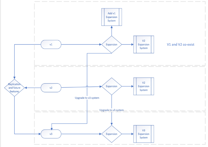
The figure below provides a visual representation to guide the expansion and interoperability of the logical network designs:
NOTE:
v1 = Non-bonded NIC port design
v2 = Static bonding NIC port design
v3 = LACP bonding NIC port design
To know how to configure network templates in the PowerFlex Manager, see PFxM - How to configure Network Templates in PowerFlex Manager.
Affected Products
PowerFlex SoftwareArticle Properties
Article Number: 000204572
Article Type: How To
Last Modified: 18 Feb 2025
Version: 2
Find answers to your questions from other Dell users
Support Services
Check if your device is covered by Support Services.