PowerVault MD24xx: How to Install the Cable Management Arm
Summary: The following article details the process for installing the cable management arm on a PowerVault MD24xx enclosure.
This article applies to
This article does not apply to
This article is not tied to any specific product.
Not all product versions are identified in this article.
Instructions
The cable management arm is an optional component that can be installed on a rack-mounted PowerVault MD24xx enclosure. The 2U enclosures (MD2412 and MD2424) ship with a single cable management arm (CMA) and the 4U enclosure (MD2460) ships with two cable management arms.
To begin, verify that all parts are present prior to beginning the installation of the CMA (see middle image below).
The first step in the installation process is to ensure that you install the brackets properly on the correct sides. Each of the brackets in the image below is marked as follows.

Figure 1: CMA Assembly - Views and Parts
The following image shows the CMAs for an MD2460 (with labels) out of the box.
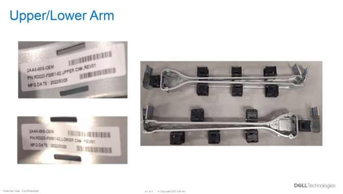
Figure 2: CMAs for MD2460 (with labels) Out Of The Box
The following steps outline the proper installation of the cable management arm onto an MD2460 enclosure. See the images below for context.
For best practices, it is recommended to install the top CMA first then populate the CMA with the power supply cables from the left and right of the enclosure. Next, install the bottom CMA and populate the CMA with the SAS cables from the left and right of the enclosure. See the image below for a fully cabled CMA.
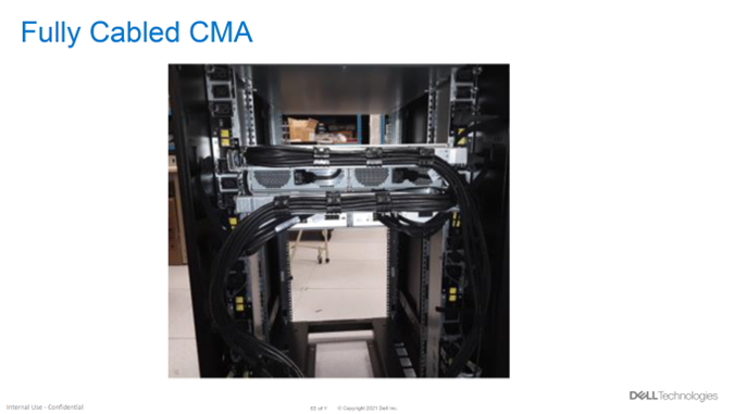
Figure 4: Fully Cabled CMA
To begin, verify that all parts are present prior to beginning the installation of the CMA (see middle image below).
The first step in the installation process is to ensure that you install the brackets properly on the correct sides. Each of the brackets in the image below is marked as follows.
- INNER-R - This bracket is installed on the inside part of the rail on the left side of the enclosure when looking at it from the rear.
- INNER-L - This bracket is installed on the inside part of the rail on the right side of the enclosure when looking at it from the rear.
- OUTER-R - This bracket is installed on the outside part of the rail on the left side of the enclosure when looking at it from the rear.
- OUTER-L - This bracket is installed on the outside part of the rail on the right side of the enclosure when looking at it from the rear.
NOTE: The rapid rails are installed as if you are standing in front of the enclosure, not the rear. The brackets for the CMA are attached to the rear of the enclosure’s rails and are labeled as if standing in front of the enclosure.
Figure 1: CMA Assembly - Views and Parts
The following image shows the CMAs for an MD2460 (with labels) out of the box.
Figure 2: CMAs for MD2460 (with labels) Out Of The Box
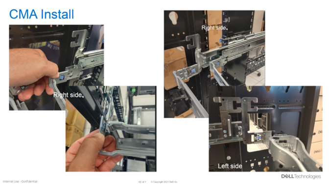
The following steps outline the proper installation of the cable management arm onto an MD2460 enclosure. See the images below for context.
- When looking at the enclosure from the rear, install the two CMA brackets (marked Inner-R and Outer-R) on the left rail as shown in the images below.
- When looking at the enclosure from the rear, install the two CMA brackets (marked Inner-L and Outer-L) on the right rail as shown in the images below.
Figure 3: Installation of Cable Management Arm to MD2460 Enclosure
For best practices, it is recommended to install the top CMA first then populate the CMA with the power supply cables from the left and right of the enclosure. Next, install the bottom CMA and populate the CMA with the SAS cables from the left and right of the enclosure. See the image below for a fully cabled CMA.
Figure 4: Fully Cabled CMA
Affected Products
PowerVault MD2412, PowerVault MD2424, PowerVault MD2460Article Properties
Article Number: 000214344
Article Type: How To
Last Modified: 22 Sep 2023
Version: 5
Find answers to your questions from other Dell users
Support Services
Check if your device is covered by Support Services.