Dell Networking SONiC: Dynamic Host Configuration Protocol (DHCP) Relay
Summary: This article explains about Dynamic Host Configuration Protocol (DHCP) in Dell Networking SONiC. This article uses a switch running Dell SONiC 4.1.
This article applies to
This article does not apply to
This article is not tied to any specific product.
Not all product versions are identified in this article.
Instructions
|
Prerequisites
Standard interface naming is used to demonstrate the Concepts. See Dell article 202172 Dell Networking S-Series: Basic Interface Configuration - SONiC 4.0 for more information regarding interface naming
|
Index
IntroductionDHCP Relay
DHCP in an MC-LAG setup
DHCP Relay Information Option
Hop Limit
Source Interface Selection
DHCP Relay over IPv6 Next Hops
DHCP Relay between VRFs
Virtual Subnet Selection Sub-option
DHCP Relay in a VXLAN Deployment
DHCP Relay and Static Anycast Gateway
Handling DHCPv4 Packets with Relay Agent Options
Server Identifier Override Sub-Option
Scalability
DHCP Relay Show Commands
Introduction
The dynamic Host Configuration Protocol (DHCP) is a network protocol that simplifies assignment of IP addresses and other information to network devices. In addition, IP addresses, DHCP also assigns subnet mask, default gateway address, domain name server (DNS) address, and other configuration parameters. Enterprise SONiC supports DHCP relay. This section provides an overview and configuration information about DHCP relay.DHCP relay
DHCP relay is any device that forwards DHCP packets between DHCP clients and DHCP servers between different subnets. You can configure your switch to function as a DHCP relay in a network.When a DHCP client requests for an IP address from a DHCP server, the client is not aware of the subnet it is going to belong. When a client is connected to a network, it sends a DHCP DISCOVER message as a broadcast. If the DHCP server resides within the same LAN or VLAN, the server assigns an IP address to the client directly.
If the DHCP server resides in a different broadcast domain, routers in the network do not forward the DHCP DISCOVER messages from clients by default. If you configure a device as a DHCP relay agent in your network, the relay agent can receive the DHCP DISCOVER broadcast messages and send a unicast request to the DHCP server on behalf of the DHCP client.
A DHCP relay agent enables DHCP clients to receive IP addresses from a DHCP server, even if the server is in a different network or VLAN.
DHCP relay operation:
In figure1, DHCP clients are connected to the interface of a relay device which belongs to VLAN 10. DHCP Server 1 and DHCP Server 2 are connected to VLAN 20 and VLAN 30 respectively. When you configure a DHCP relay on the device, it forwards DHCP requests to the respective DHCP server and the reply from the server to clients.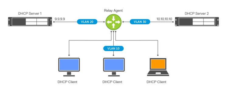
Figure 1: Example of DHCP topology
- Enable DHCP relay on the interface that you plan to use for relaying:
sonic(conf-if)# ip dhcp-relay dhcp-server-ip-address vrf vrf-name
Enter the server address. You can add up to four addresses:
dhcp-server-ip-address(Optional) Enter the VRF name:
vrf-name
admin@DELLSONiC:~$ sonic-cli
DELLSONiC# configure terminal
DELLSONiC(config)# interface Vlan 100
DELLSONiC(config-if-Vlan100)# ip dhcp-relay 10.10.200.12
DELLSONiC(config-if-Vlan100)# show configuration
!
interface Vlan100
 ip address 10.10.100.1/24
 ip dhcp-relay 10.10.200.12
DELLSONiC(config-if-Vlan100)#
DHCP relay in an MC-LAG setup
In an MC-LAG setup, a DHCP client sends a DHCP DISCOVER packet to either of the MC-LAG peers. When one of the peers receives the packet, it relays the packet to the DHCP server. When the DHCP server sends a response, the same MC-LAG peer that relayed the DHCP DISCOVER packet relays the reply from the server to the client.Configuration guidelines for MC-LAG:
- Configure the same DHCP servers on the MC-LAG peer switches.
- Configure DHCP relay to use link-selection and source interface options. This configuration ensures that the response from the server is received by the switch that relayed the DHCP packet.
- Ensure that the DHCP server is reachable from both MC-LAG peers.

Figure 2: DHCP relay in MC-LAG
DHCP relay information option
In a network where a single routing is involved, the DHCP relay uses the gateway IP address that is found in the giaddr field of the relayed packet to assign an IP address to the DHCP client. Rogue actors can spoof DHCP requests to gain unauthorized access to the network.To prevent rogue devices from gaining access to the network, network administrators may place clients DHCP servers in different networks. You can use the DHCP relay information option or DHCP option 82 to explicitly specify the subnet on which the DHCP client resides. The relay agent adds the suboption to the packet to specify the client subnet and the DHCP server uses the sub-option value, instead of giaddr, to assign the DHCP address and lease.
NOTE: The link-selection sub-option is applicable for DHCPv4 clients only and is not applicable for DHCPv6 clients.
The following figure 3 illustrates how DHCP relay link selection works.
- A DHCP client sends a DHCP request.
- The relay agent receives the broadcast packet and adds the link-selection sub-option with the 192.168.0.1 address.
- The relay agent sets the giaddr field that is based on the configured source interface. If the source interface is configured as loopback 0, the giaddr is set to 103.103.103.103. The giaddr must be reachable from the server.
- The DHCP server identifies the client subnet from the link-selection option and allocates the address from the 192.168.0.x address pool. The server generates the offer packet and sends it to the IP address specified in the giaddr.

Figure 3: DHCP relay
Hop limit
DHCP clients usually set the hop count field in the DHCP packet to 0. When forwarding DHCP packets, the relay agent increments the hop count by 1. If the hop count in the DHCP packet is greater than or equal to the maximum number of hops configured on the relay agent, the device discards the packet.The hop limit ensures that the DHCP packets are not looped in the network where multiple relay agents are present. The default value of the maximum number of hops is 10 which you can configure to a value from 1 to 16.
The hop limit configuration is per-interface (client facing) and applies to both DHCPv4 and DHCPv6 packets. The hop limit is only enforced for packets that are relayed to the server. It is not applicable for response packets that are received from a server. The interface counter is maintained to track the number of packets dropped due to the hop limit.
- Set the maximum hop limit. (Optional):
sonic(conf-if-Vlan100)# ip dhcp-relay max-hop-count hop-count
Specify the hop count. The range is from 0 to 16. The default value is 10:
hop-count
admin@DELLSONiC:~$ sonic-cli
DELLSONiC# configure terminal
DELLSONiC(config)# interface Vlan 100
DELLSONiC(config-if-Vlan100)# ip dhcp-relay max-hop-count 15
DELLSONiC(config-if-Vlan100)# show configuration
!
interface Vlan100
 ip address 10.10.100.1/24
 ip dhcp-relay 10.10.200.12
 ip dhcp-relay max-hop-count 15
DELLSONiC(config-if-Vlan100)#
Source interface selection
DHCP relay provides a source interface configuration option which specifies the source address to be used for relayed packets. If you do not specify the source interface, the source IP address in the relayed packet is automatically determined based on the outgoing interface. The system chooses the first address (IPv4 or IPv6) configured on the interface which falls in the same network as the destination address or next hop router.The source interface configuration option is a per-interface that is client facing and applies to both DHCPv4 and DHCPv6 packets. If the configured source interface does not have any IP address, the source IP address in the relayed packet is determined based on the outgoing interface. If you modify the address on the source interface, the relay agent uses the updated IP address for relaying packets.
If the link-selection sub-option is enabled, configure a source interface that is reachable from the server. If you do not configure a source interface, the link-selection sub-option is not added to the relayed packet.
- Enter source interface selection on an interface:
NOTE:Interface is saved in Native Interface Format.
sonic(conf-if)# ip dhcp-relay source-interface interface
admin@DELLSONiC:~$ sonic-cli
DELLSONiC# configure terminal
DELLSONiC(config)# interface Vlan 100
DELLSONiC(config-if-Vlan100)# ip dhcp-relay source-interface Eth 1/10
DELLSONiC(config-if-Vlan100)# show configuration
!
interface Vlan100
 ip address 10.10.100.1/24
 ip dhcp-relay 10.10.200.12
 ip dhcp-relay source-interface Ethernet36
 ip dhcp-relay max-hop-count 15
DELLSONiC(config-if-Vlan100)#
DHCP relay over IPv6 next hops
In data center network deployments as shown in the following figure 4, the DHCP server is reachable through an IPv6 underlay network. DHCP relay is enabled on the Leaf 1 switch, which has BGP neighborship with Spine 1. The DHCP server is connected to Leaf 2 switch which also has BGP neighborship with Spine 1.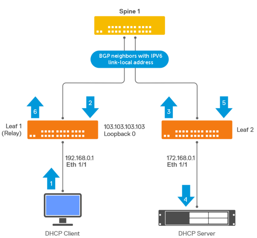
Figure 4: DHCP relay over IPv6 next hops
The interfaces between the leaf and spine switches do not have IPv4 addresses, but they are enabled for IPv6 forwarding using link-local addresses. BGP peering between Leaf and Spine switch is established using IPv6 link-local addresses. BGP supports RFC 5549, which allows an IPv4 prefix to be carried over an IPv6 next hop.
On Leaf 1, the IPv4 route to the DHCP server is learned through BGP and indicates the link-local next hop address of Spine 1. Spine 1 also has an IPv4 route that indicates the link-local next hop address of Leaf 2.
The following explains how the DHCP relay works over IPv6 next hops:
- DHCP client generates the request.
- The relay agent on Leaf 1 is configured to use Loopback0 as the source interface. The relay agent sets the giaddr and source IPv4 address to 103.103.103.103, and forwards the request to the DHCP server whose IP address is 172.16.0.2 as per the BGP RFC 5549 route.
- Leaf 2 receives the relayed DHCP request from Spine 1 and forwards it to the DHCP server which is directly connected.
- The DHCP Server receives the relayed DHCP request, generates an offer packet, and sends it to the IP address specified in the giaddr, which is the Leaf 1 loopback address 103.103.103.103.
- Leaf 2 has a BGP RFC5549 route to reach the loopback address of Leaf 1 which is 103.103.103.130. The DHCP offer is forwarded to the relay agent as per the BGP route.
- Leaf 1 receives the response from the DHCP server, strips option 82, and forwards it to the client.
- Enable DHCP relay on the interface that you plan to use for relaying:
sonic(conf-if)# ipv6 dhcp-relay dhcp-server-ipv6-address vrf vrf-name
Enter the server IPv6 address. You can add up to four addresses:
dhcp-server-ipv6-address(Optional) Enter the VRF name:
vrf vrf-name
- Enter source interface selection on an interface:
sonic(conf-if)# ipv6 dhcp-relay source-interface interface
- (Optional) Set the maximum hop limit:
sonic(conf-if-Vlan100)# ipv6 dhcp-relay max-hop-count hop-count
Specify the hop count. The range is from 1 to 16. The default value is 10:
hop-count
- (Optional) Specify how to handle a DHCP relay packet that comes from another relay agent:
sonic(conf-if)# ip dhcp-relay policy-action [discard | append | replace]
admin@DELLSONiC:~$ sonic-cli
DELLSONiC# configure terminal
DELLSONiC(config)# interface Vlan 100
DELLSONiC(config-if-Vlan100)# ipv6 dhcp-relay 2001:db8:4444::7777
DELLSONiC(config-if-Vlan100)# show configuration
!
interface Vlan100
 ip address 10.10.100.1/24
 ipv6 address 2001:db8:3333::7777/80
 ipv6 dhcp-relay 2001:db8:4444::7777
DELLSONiC(config-if-Vlan100)#
DHCP relay between VRFs
The DHCP relay agent supports forwarding of client requests to a server that is located in a different VRF. For example, the client is connected to an interface bound to the default VRF, and the server can reside in user VRF. For such deployments, You can configure an option to specify the VRF name in which the DHCP server resides. If you do not specify the VRF name, the system assumes that the DHCP server resides in the default VRF. DHCP relay supports configuring multiple DHCP servers for a given client interface, and all these DHCP servers must reside in the same VRF. You can configure only one server VRF per client-facing interface.
NOTE:The client VRF is derived from the interface on which the relay is configured.
If you are using DHCPv4 relay, you must enable link-selection when the client and the server are in different VRFs. The link-selection sub-option must use an interface that is bound to server VRF. This configuration is required to ensure that the response from the server is received by the DHCPv4 relay. If the client and server are in the same VRF, you need not configure link-selection as the giaddr is also in the server VRF.
- Enable DHCP relay on the interface that you plan to use for relaying:
sonic(conf-if)# ip dhcp-relay dhcp-server-ip-address vrf vrf-name
Enter the server address. You can add up to four addresses:
dhcp-server-ip-address(Optional) Enter the VRF name:
vrf-name
- (Optional) Enable link-selection sub-option on an interface:
sonic(conf-if)# ip dhcp-relay link-select
- (Optional) To add VRF information in the DHCP packet that is sent to the DHCP server, specify the VRF-select option:
sonic(conf-if)# ip dhcp-relay vrf-select
admin@DELLSONiC:~$ sonic-cli
DELLSONiC# configure terminal
DELLSONiC(config)# interface Vlan 100
DELLSONiC(config-if-Vlan100)# ip dhcp-relay 10.10.200.12 vrf Customer1
DELLSONiC(config-if-Vlan100)# show configuration
!
interface Vlan100
 ip address 10.10.100.1/24
 ip dhcp-relay 10.10.200.12 vrf Customer1
DELLSONiC(config-if-Vlan100)#
Virtual subnet selection sub-option
DHCP relay supports multiple clients on different VRFs which share overlapping IP addresses. In such VRF deployments, the DHCP server must be aware of the VRF of the client so that the address allocation can be done based on that VRF. To provide VRF information, DHCP relay includes the sub-option 151 for DHCPv4 and sub-option 68 for DHCPv6 as defined in RFC 6607.The virtual subnet selection sub-option (type 0) carries the ASCII VRFNAME configured on the incoming interface to which the client is connected. If the incoming interface is in default VRF, the sub-option is not added to the relayed packet.
To ensure interoperability, enable the virtual subnet selection sub-option only when the DHCP server supports address allocation based on VRF. Some servers may not recognize the sub-option and may still allocate lease in the default VRF space. DHCP relay does not discard these replies from the server.
In the following figure 5, both DHCP Client 1 and DHCP Client 2 use the same address space. If you configure a virtual subnet selection sub-option on the DHCP Relay switch, the relay device includes the sub-option when sending the packet to the DHCP server.

Figure 5: Virtual subnet selection sub-option
DHCP relay in a VXLAN deployment
You can configure a DHCP relay in a VXLAN BGP EVPN deployment to provide DHCP services to EVPN clients or VMs. The following figure 6 shows a typical deployment in VXLAN networks. The client and server can be in the same or different VRF domains.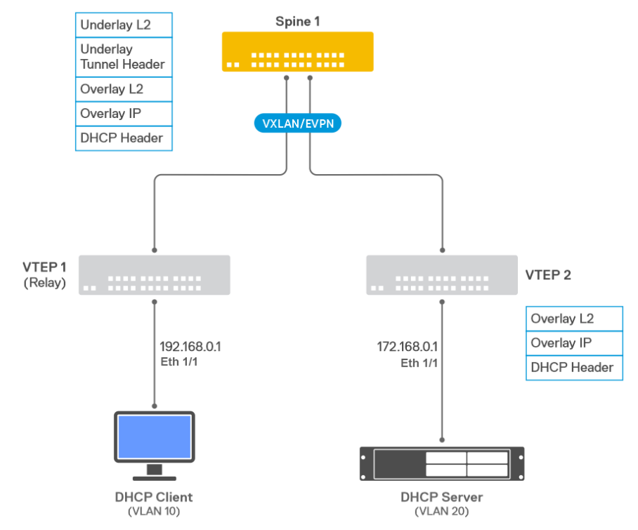
Figure 6: DHCP relay in a VXLAN deployment
The following illustrates the functioning of a DHCP relay in a VXLAN deployment:
- DHCP client is attached to VTEP1 on VLAN 10, which is bound to VrfRed.
- DHCP relay is enabled on VTEP1 for VLAN 10.
- DHCP server is on VTEP2 and is connected to VLAN 20, which is bound to VrfRed.
- VTEP1 has a BGP EVPN type-5 route to the DHCP server 172.16.0.1 that indicates VXLAN tunnel next hop.
- The DHCP relay forwards the incoming packet to 172.16.0.1 with giaddr set to 192.168.0.1. The relay is unaware of the VxLAN tunnels.
- VTEP1 adds underlay Layer 2 tunnel headers and forwards the packet to the destination VTEP2.
- VTEP2 removes the underlay Layer 2 and tunnel headers and forwards the DHCP packet to the server.
- DHCP server responds to giaddr 192.168.0.1. VTEP2 has BGP EVPN type-5 route to the relay agent IP address 192.168.0.1 that indicates the tunnel next hop.
- VTEP2 adds underlay Layer 2 tunnel headers and sends the response packet to VTEP1.
- The DHCP relay agent on VTEP1 receives the response from the server, removes option 82, and forwards the packet to the client on VLAN 10.
NOTE:DHCP relay in BGP EVPN deployments is applicable to Layer 3 VNI configurations. For Layer 2 VNI configurations, there is no need for DHCP relay, as the client and server are directly reachable over extended VLAN.
DHCP relay and Static Anycast Gateway
Static Anycast Gateway (SAG) allows multiple switches to simultaneously route packets using a common gateway address in an active/active router configuration. Each switch is configured with the same set of virtual IP address and a virtual MAC address.DHCP relay requires an IP address to identify the subnet of the downstream or client-facing interface. If the client interface is enabled for SAG, the DHCP relay uses the SAG IPv4 address as the giaddr. If the associated SAG interface does not have any IP address that is assigned, the relay agent discards the packet. As an identical SAG IP address is configured on Leaf switches, the response from the server may land on a different leaf switch, and may not reach the leaf switch that relayed the DHCP packet. To avoid this issue, use link-selection option with the source interface.
In the following figure7, 192.168.0.1 is used as the SAG gateway for VLAN10 on the leaf switch. DHCP relay is enabled on VLAN10. To relay a DHCP packet to the DHCP server, the giaddr field is set to 55.55.55.55. The DHCP server uses link-selection sub-option 5 to identify the client subnet to be leased. The response from the DHCP server is sent to the Loopback IP which is unique to the originating leaf switch.

Figure 7: DHCP relay and Static Anycast Gateway
DHCP relay on unnumbered IPv4 interfaces
You can configure DHCP relay on unnumbered point-to-point links. The IPv4 unnumbered configuration enables Layer 3 processing without assigning an explicit IPv4 address.The unnumbered interface uses the IPv4 address of another interface that is already configured on the router. You can use the IPv4 unnumbered configuration to save network address space and simplify the switch configuration.
DHCP relay supports forwarding packets to a server through an IPv4 unnumbered interface with the following limitations:
- Only loopback interfaces are supported as donor interfaces.
- IPv4 unnumbered configuration is supported only on Ethernet and port channel interfaces.
- IPv4 unnumbered configuration is supported only on the default VRF.
NOTE:Both ends of the link between the relay and the server must be configured as unnumbered interfaces. The client facing downstream interface must have an IPv4 address associate as the server must know the client subnet to assign the DHCP lease.
In the following figure 8, IPv4 unnumbered is configured on the Eth1/4 interface, which is a point-to-point link between the relay and server. OSPFv2 is enabled on relay switch and server switch, and the loopback network addresses are advertised.

Figure 8: DHCP relay on unnumbered IPv4 interfaces
The client subnet is also advertised through OSPFv2 so that the server can reply to the relay switch. The giaddr in the relayed packet is set to 192.168.0.1. The source IPv4 address in the relayed packet is determined by the routing stack.
You can also enable link-selection in an IPv4 unnumbered setup. If the client subnet is not reachable from the server, the giaddr is set to the Loopback 1 address which is 103.103.103.103.
Handling DHCPv4 packets with relay agent options
To support different network configurations, such as cascading relays, the relay agent provides three different options to handle incoming DHCPv4 packets that already have relay agent options:- Discard - The relay agent discards the incoming packet (default).
- Append - The relay agent appends its own set of relay options to the packet, leaving the incoming options intact. If the length of relay agent information exceeds the max limit of 255 bytes, the packet is discarded.
- Replace - The relay agent removes the incoming options and adds its own set of options to the packet.
- (Optional) Specify how to handle a DHCP relay packet that comes from another relay agent.
sonic(conf-if)# ip dhcp-relay policy-action [discard | append | replace]
admin@DELLSONiC:~$ sonic-cli
DELLSONiC# configure terminal
DELLSONiC(config)# interface Vlan 100
DELLSONiC(config-if-Vlan100)# ip dhcp-relay policy-action discard
DELLSONiC(config-if-Vlan100)# show configuration
!
interface Vlan100
 ip address 10.10.100.1/24
 ip dhcp-relay 10.10.200.12
 ip dhcp-relay source-interface Ethernet40
 ip dhcp-relay max-hop-count 15
 ip dhcp-relay policy-action discard
DELLSONiC(config-if-Vlan100)#
Server identifier override sub-option
DHCPv4 relay supports server identifier override sub-option 11 as defined in RFC5107. This sub-option enables the relay to act as the DHCPv4 server so that unicast DHCPv4 packets come to the relay agent instead of directly going to the server. The relay can add appropriate sub-options on the unicast packets. The server identifier override sub-option is automatically added when the link-select sub-option or VSS sub-option is enabled.If the DHCPv4 server does not support the server identifier sub-option, then the unicast DHCPv4 packets from the client are sent directly to the server bypassing the relay agent.
This sub-option is only applicable to DHCPv4 relay agent.
Scalability
- You can enable a maximum of four relay addresses per interface.
- DHCPv4 and DHCPv6 relay can handle up to 2000 DHCP clients.
- You can enable a maximum of 4000 Layer 3 interfaces for DHCPv4 relay.
- You can enable a maximum of 4000 Layer 3 interfaces for DHCPv6 relay.
DHCP Relay Show Commands
DELLSONiC# show ip dhcp-relay
  brief       Display IP DHCP relay information in brief
  detailed    Display IP DHCP relay information in detail
  statistics  Display IP DHCP relay statistics
DELLSONiC# show ip dhcp-relay brief
------------------------------------------------
Interface Name    DHCP Helper Address
------------------------------------------------
Vlan100           10.10.200.20


DELLSONiC# show ipv6 dhcp-relay brief
------------------------------------------------
Interface Name    DHCP Helper Address
------------------------------------------------
Vlan100           2001:db8:4444::7777
DELLSONiC#
DELLSONiC# show ip dhcp-relay detailed Vlan 100

Relay Interface: Vlan100


Server Address: 10.10.200.20
Server VRF: Not Configured
Source Interface: Not Configured
Link Select: disable
VRF Select: disable
Max Hop Count: 10
Policy Action: discard
Circuit-id Format: %p
DELLSONiC#
DELLSONiC# show ip dhcp-relay statistics Vlan 100
BOOTREQUEST messages received by the relay agent        : 4
BOOTREQUEST messages forwarded by the relay agent       : 2
BOOTREPLY messages forwarded by the relay agent         : 0
DHCP DISCOVER messages received by the relay agent      : 0
DHCP OFFER messages sent by the relay agent             : 0
DHCP REQUEST messages received by the relay agent       : 0
DHCP ACK messages sent by the relay agent               : 0
DHCP RELEASE messages received by the relay agent       : 0
DHCP DECLINE messages received by the relay agent       : 0
DHCP INFORM messages received by the relay agent        : 0
DHCP NACK messages sent by the relay agent              : 0
Total number of DHCP packets dropped by the relay agent : 0
Number of DHCP packets dropped due to an invalid opcode : 0
Number of DHCP packets dropped due to an invalid option : 0
DELLSONiC#
Affected Products
Enterprise SONiC Distribution, PowerSwitch S5048F-ON, PowerSwitch S5148F-ON, PowerSwitch S5212F-ON, PowerSwitch S5224F-ON, PowerSwitch S5232F-ON, PowerSwitch S5248F-ON, PowerSwitch S5296F-ON, PowerSwitch S5448F-ONArticle Properties
Article Number: 000218658
Article Type: How To
Last Modified: 20 Feb 2024
Version: 4
Find answers to your questions from other Dell users
Support Services
Check if your device is covered by Support Services.