PowerFlex: Procedure to update firmware to mitigate an issue of NVDIMM batteries losing charge
Summary: Procedure to update firmware to mitigate an issue of NVDIMM batteries losing charge on PowerFlex Rack and Appliance (R650, R750) nodes.
This article applies to
This article does not apply to
This article is not tied to any specific product.
Not all product versions are identified in this article.
Instructions
Dell PowerFlex 15G systems support a configuration that contains NVDIMMs which provide persistent memory required for the Fine Granularity feature. This procedure contains the steps to update the iDRAC and CPLD versions to the following:
- iDRAC 7.10.50.201
- CPLD 1.1.1
Download Locations
-
PowerFlex rack/RCM: Dell Support PowerFlex Rack Drivers
-
PowerFlex appliance/IC: Dell Support PowerFlex Appliance Drivers
In the context of PowerFlex Engineered Systems, the component versions listed are controlled by the system catalog (RCM for Rack and IC for Appliance) The target RCM and IC versions containing the correct component versions are:
- RCM:
- 3.6.7.0
- 3.7.6.0
- 3.8.1.0
- IC:
- 38.367.00
- 46.376.00
- 46.381.00
It is always recommended that customers upgrade PowerFlex Engineered systems using the catalogues and have a goal of being compliant with the catalogues. In this case, it is NOT appropriate to simply upgrade to the target catalogues as it can expose undesirable behavior. At a minimum this procedure should be used to ensure that any existing NVDIMM Battery issues are identified and remediated before a catalog upgrade. The decision to leave a system in a non-compliant or modified-compliant state or to proceed with a catalog upgrade is left to the customer.
The new iDRAC version will now check on the NVDIMM Battery cell voltages when it is enabled. It logs an error if the cell voltages are below a defined threshold. It will also log an event with a severity of info when the NVDIMM Battery transitions between READY and ENABLED states.
The new CPLD design tracks the NVDIMM Battery enable state and transitions back to the Ready state after a fixed amount of time.
- As a result of the issue above, there is a possibility that the NVDIMM Battery in the system could be damaged and need to be replaced. This procedure accounts for this possibility.
- This update of the iDRAC and CPLD must follow a specific sequence. The sequence requires iDRAC to be upgraded first, then the CPLD is updated after. This helps identify if the battery has failed.
Procedure Overview
To fully address the issue, we need to do the following:
- Identify any NVDIMM Batteries in the system lack sufficient charge.
- Since this specific condition is not being reported in earlier iDRAC versions, we must update iDRAC to the version indicated above (or higher). This new version of iDRAC will report BAT0021 or BAT0017 errors if it detects an NVDIMM Battery that is discharged.
- Update the iDRAC to the version indicated on all nodes in the system.
- Request replacement NVDIMM Batteries for every one that is reported as discharged and bad.
- Do not proceed with the CPLD update on nodes with bad NVDIMM Batteries until you have replaced the bad battery.
- Replacement batteries do not come fully charged and require up to 75 minutes to achieve full charge after installation.
Caution: Placing the unit into production before the battery is fully charged can result in Data Loss
-
-
- For nodes with good NVDIMM Batteries, you can proceed with the CPLD firmware update.
-
- After replacing the bad batteries, proceed to update the CPLD firmware using the iDRAC.
- The node needs to be placed in service mode prior to completing the update
- The node reboots and then performs the CPLD update.
- Once the node reboots after the CPLD update, you are now ready to take the node out of Maintenance mode/Service mode.
- Once the node is out of Maintenance, a Rebuild and a Rebalance operation will start.
- NOTE: Wait for the Rebuild and Rebalance to complete before proceeding to update the next node in the cluster
- For PowerFlex Engineered systems some steps can be automated by PowerFlex Manager using the "Single-Component Upgrade (SCU)" feature in versions 4.5.x and above. This feature is available using RPQ for versions lower than 4.6 As such the main procedural workflow assumes that SCU is not available and only describe SCU operations as alternative procedures on relevant steps.
Prerequisites
This procedure requires a minimum BIOS version to be successful. The following table lists the expected iDRAC and BIOS versions in each active catalog for PowerFlex Engineered Systems. Confirm the BIOS version on the iDRAC dashboard or node compliance view in PowerFlex Manager.
| RCM | IC | iDRAC | BIOS | BIOS Upgrade |
| 3.6.3.0 | 38.363.00 | 5.10.30.00 | 1.6.5 | Required |
| 3.6.3.1 | 38.363.01 | 6.00.30.202 | 1.8.2 | Recommended |
| 3.6.3.3 | 38.363.03 | 6.10.30.20 | 1.9.2 | Recommended |
| 3.6.4.0 | 38.364.00 | 6.10.80.00 | 1.10.2 | OK |
| 3.6.5.0 | 38.365.00 | 6.10.80.00 | 1.11.2 | OK |
| 3.6.5.1 | 38.365.01 | 6.10.80.00 | 1.12.2 | OK |
| 3.6.6.0 | 38.366.00 | 7.00.60.00 | 1.12.2 | OK |
| 3.7.0.0 | 40.370.00 | Contact Support | ||
| 3.7.0.1 | 40.370.01 | Contact Support | ||
| 3.7.1.0 | 40.371.00 | 6.00.30.202 | 1.8.2 | Recommended |
| 3.7.2.0 | 40.372.00 | 6.10.80.00 | 1.10.2 | OK |
| 3.7.3.0 | 45.373.00 | 6.10.80.00 | 1.11.2 | OK |
| 3.7.3.1 | 45.373.01 | 7.00.30.00 | 1.11.2 | OK |
| 3.7.4.0 | 45.374.00 | 7.00.60.00 | 1.12.1 | OK |
Detailed Procedure
Step 1: Update iDRAC on all nodes in the PowerFlex cluster.
The iDRAC on these systems can be updated without rebooting the nodes. The procedure to update iDRAC is as follows.
We are updating the iDRAC without using a published catalog. Ensure that you have downloaded the firmware image to a location on your local system. The firmware version for iDRAC is needed for this procedure, and the download location is listed on the first page of the procedure.
Alternate Procedure: PowerFlex Engineered Systems with the Single-Component Upgrade (SCU) feature enabled can instead perform this step using the SCU feature by changing the target version of the iDRAC on all impacted nodes and remediating the compliance.
Perform the iDRAC FW update on all the systems in the cluster before moving on to the next step in the procedure.
-
Log in to the iDRAC9 web interface.
- Go to Maintenance, then click System Update. The Manual Update page is displayed.
- From the Manual Update tab, select Local as the Location Type.

Figure 1: iDRAC9 Update Screen
- Click Choose File, select the firmware image file for the required component, and then click Upload.
- After the upload is complete, the Update Details section displays each firmware file that is uploaded to iDRAC and its status. If the firmware image file is valid and was successfully uploaded, the Contents column displays a (+) icon next to the firmware image filename. Expand the name to view the Device Name, Current, and Available firmware version information.
- Select the required iDRAC firmware file.
- iDRAC firmware update does not require a host system reboot. Click Install to initiate the update.
When you click Install, the message Updating Job Queue is displayed.
- To display the Job Queue page, click Job Queue. Use this page to view and manage your pending firmware updates. You can click OK to refresh the current page and view the firmware update status.
- The life cycle controller restarts and the connection to the iDRAC will be reset. Wait for a few minutes to log in to the iDRAC.
If connection failure is seen, see HTTP and HTTPS FQDN Connection Failures KB PowerEdge: HTTP and HTTPS FQDN Connection Failures On iDRAC9 Firmware Version 5.10.00.00
Step 2: Check if the node has a bad NVDIMM Battery.
The new version of iDRAC 7.10.50.201 and above contains code that checks the charge in the NVDIMM Battery cells every 5 seconds and reports the following error in the iDRAC System event log (SEL) if the cell voltage is below the threshold of 1.5v.
“BAT0021: The NVDIMM battery has reached the end of its usable life or has failed”“BAT0017: The NVDIMM battery has failed.”
If one of the above messages is reported, the node has a bad NVDIMM Battery, which must be replaced.
- Do not proceed to update the CPLD on this node with a bad NVDIMM Battery. The reboot during a CPLD update hangs and will not arm the NVDIMM because of the bad battery.
- Request a replacement NVDIMM Battery.
If the iDRAC does not report an issue, the battery on this node is good and does not need to be replaced. The CPLD update can be performed on this node, and you can go to the next step.
-
PowerFlex Engineered Systems report a node health warning for any node expressing the BAT0021 or BAT0017 error. This behavior can be used to identify failed NVDIMM Batteries after the iDRAC update
-
If the BAT0017 or BAT0021 event shows up, but then a third event of BAT0016, then the battery does NOT need to be replaced!
NVDIMM engineering advised if this third event (BAT0016) is encountered, the battery does not need to be replaced.BAT0016 The NVDIMM battery is operating normally.
If all three battery alerts (BAT0021, BAT0020, BAT0016) are all seen in sequence in less than a minute, this should be considered a false alarm and the battery is considered healthy and should not be replaced.
Step 3: Prepare node - Put the SDS into Service Mode.
Use PowerFlex Manager to enter service mode.
- Log in to PowerFlex Manager and identify the target node.
- Enter Service Mode by following the procedure here
- PowerFlex Rack - Enter and Exit Service Mode
- PowerFlex Appliance - Enter and Exit Service Mode
- Select the correct PowerFlex Maintenance mode
- If the node does not have a bad NVDIMM Battery, Instant Maintenance Mode (IMM) is recommended to update the CPLD.
- Skip steps 4 and 5 (replacing the battery) and proceed with the BIOS (step 6) and CPLD upgrade (step 7)
- If the node does have a bad NVDIMM Battery, it must be replaced.
- In this case, the node should be put in Protected Maintenance Mode (PMM) to account for the time the replacement battery takes to charge.
- If the node does not have a bad NVDIMM Battery, Instant Maintenance Mode (IMM) is recommended to update the CPLD.
- This procedure causes a rebalance process to start, it is recommended to plan this procedure for a scheduled maintenance window.
- If using PMM before the NVDIMM Battery replacement (steps 4-5), you can stay in PMM Maintenance mode for the BIOS and CPLD update (steps 6-7)
Step 4: Replace NVDIMM Battery.
See the Solve documentation for PowerFlex nodes available at the link provided below for instructions to replace the NVDIMM Battery.
Download the SolVe documentation for "NVDIMM battery" for the appropriate node type R650/R750 on 15G.
PowerFlex Rack > Replacement > Field replacement procedures > 15G > Components Replacement Procedures > Manual Components Replacement Procedures > [choose appropriate node type] > Replacing an NVDIMM battery….
-
Skip the following sections in the "Replacing the NVDIMM Battery" documentation.
Remove the storage devices from PowerFlex.
Reasons storage devices should not be removed:
- Removing storage devices during this procedure cause an unnecessary rebuild of the entire node, extending the maintenance significantly.
- Since this is a planned reboot and not a power loss event, the NVDIMM subsystem does not rely on the power from batteries to complete the saved operation. The power is sourced from the PSUs even when the batteries are bad.
- The reboot causes the system to report an error with the NVDIMM Battery during power-up. But the data in the NVDIMM has been saved and loss of data is not experienced.
Step 5: Wait for the replaced batteries to charge.
If you have replaced the NVDIMM Battery on a particular node, please power on the system. The system will not boot completely. The BIOS will stop waiting for the batteries to charge since a replacement NVDIMM Battery may not have sufficient charge needed by the system to protect the data in the NVDIMM. The batteries may take about 60-75 minutes to charge. You can try restarting the system after 60-75 minutes and the node should power up and arm the NVDIMM subsystem as well.
- Plan your maintenance window based on this 60-75 minutes for every node that must have a replacement battery.
Step 6: Update BIOS if required
The CPLD version used to fix the underlying issue in this KB requires a minimum BIOS of 1.8.2. For RCM and IC compliance 1.10.2 or later is recommended.
Systems identified in the table above that need an updated BIOS should complete this step. If your system is not indicated, then the section can be skipped and you can go to the next step.
-
You should be in service mode on the current node - if not please enter service mode now.
-
Proceed with a BIOS upgrade to 1.10.2 or later
- Download: Dell Support PowerEdge R650 Drivers
Click "Older Versions" to choose a version that will be in your next RCM/IC version.
- Dell PowerEdge BIOS upgrade procedure for 15G: PowerEdge: Recommended BIOS and iDRAC9 Updated for 15th Generation Servers
Step 7: Update CPLD to version 1.1.1.
Note: You should be in service mode on the current node - if not please enter service mode now.
The CPLD update causes a reboot of the node. The procedure to update the CPLD is as follows.
Ensure that you have downloaded the CPLD firmware image to a location on your local system. The CPLD firmware version needed is 1.1.1 and can be downloaded from Dell Support PowerEdge R650 Drivers
This step is not automated by PowerFlex manager and must be completed from the iDRAC interface using the procedure below.
-
Log in to the iDRAC9 web interface.
-
Go to Maintenance, then click System Update. The Manual Update page is displayed.
-
From the Manual Update tab, select Local as the Location Type.
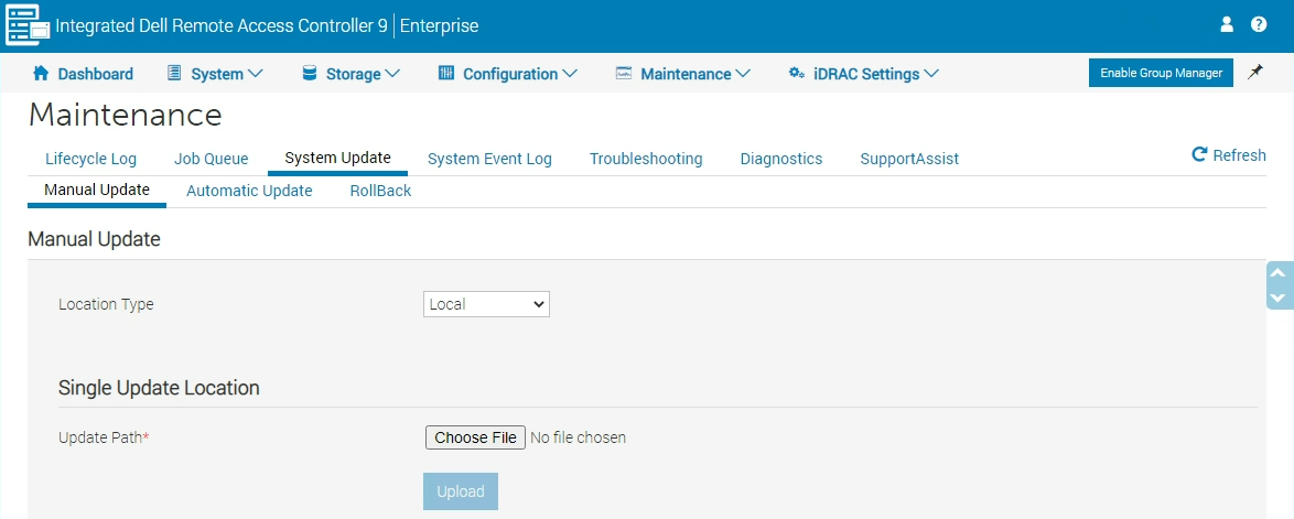
Figure 1: iDRAC9 Update Screen - Click Choose File, select the firmware image file for the required component, and then click Upload.
- After the upload is complete, the Update Details section displays each firmware file that is uploaded to iDRAC and its status. If the firmware image file is valid and was successfully uploaded, the Contents column displays a (+) icon next to the firmware image filename. Expand the name to view the Device Name, Current, and Available firmware version information.
- Select the required CPLD firmware file.
- A CPLD firmware update requires a host system reboot. Click Install to initiate the update.
When the user clicks Install the message Updating Job Queue is displayed.
- To display the Job Queue page, click Job Queue. Use this page to view and manage your pending firmware updates. You can click OK to refresh the current page to view the status of the firmware update.
This will reboot the system, and on the reboot, the system loads the new CPLD FW.
Step 8: Take the node out of Service mode.
PowerFlex version 4.x, see 'Dell Powerflex 4.x Administration Guide'.
Prerequisites: Ensure that you have the IP address and admin login credentials for accessing PowerFlex Manager. If necessary, the customer can provide you with the necessary information.
-
Power on the node, if you have not already done so after the CPLD update. The operating system will boot up and all PowerFlex processes will start up automatically.
-
After the node is up from your browser, log back in to PowerFlex Manager as an admin user.
-
On the menu bar, click Monitoring > Alerts and confirm that no disconnect message appears for an SDS or an SDC host, or for an SDR or SDT, if applicable.
- For an ESXi node, perform the following:
- From the vSphere Web Client, ensure that the node is displayed as on and connected in both Hosts and Clusters view.
- Right-click the node and select Exit Maintenance Mode.
- Expand the server and select the Storage VM (SVM). If the SVM does not power on automatically, power it on manually.
- Exit the SDS from maintenance mode:
- If an SDR is configured on the node, remove the SDR from maintenance mode.
PowerFlex version 3.x, see 'Upgrade Dell PowerFlex to v3.6.x' guide.
Prerequisites: Ensure that the user have the following credentials (available from the administrator): PowerFlex presentation server IP address or hostname, used for accessing the PowerFlex UI
- Power on the node if it has not already been done following the CPLD update. The operating system boots up and all PowerFlex processes start up automatically
- Exit the node from maintenance mode: Return the node to operation
- If an SDR is configured on the node, remove the SDR from maintenance mode.
Step 9: Go to the next node in the cluster.
The sequence of steps 2 through step 8 should be completed for all the nodes in the cluster, one at a time. Once all the nodes have been upgraded the process is complete.
Step 10: Complete a catalog update (optional)
As a result of the procedure the system will not be compliant with a published catalog. As a best practice, PowerFlex recommends updating to the latest published catalog using normal processes. This is an optional step from the perspective of this document, but highly recommended.
The next catalog upgrade should be to a point equal to or greater than the target catalog versions at the beginning of the document.
Additional Information
Note: For some scenarios If you update the CPLD on the host, The NQN will also change. Be sure to update the NQN on the storage side once the host is rebooted.
Affected Products
PowerFlex rack, PowerFlex ApplianceProducts
PowerFlex appliance R650, PowerFlex appliance R6525, PowerFlex appliance R660, PowerFlex appliance R6625, Powerflex appliance R750, PowerFlex appliance R760, PowerFlex appliance R7625, PowerFlex rack connectivity, PowerFlex rack HW
, PowerFlex rack RCM Software, PowerFlex appliance R640, PowerFlex appliance R740XD, PowerFlex appliance R7525, PowerFlex appliance R840
...
Article Properties
Article Number: 000228450
Article Type: How To
Last Modified: 12 Jan 2026
Version: 15
Find answers to your questions from other Dell users
Support Services
Check if your device is covered by Support Services.