PowerVault ME5: Troubleshooting iSCSI Controller Ethernet Port Link Negotiation or Link Down
Summary: This article helps with isolating faults when an Ethernet port link does not come up or the port does not negotiate the expected link speed with PowerVault ME5 iSCSI controller modules. ...
This article applies to
This article does not apply to
This article is not tied to any specific product.
Not all product versions are identified in this article.
Instructions
- Checklist when a controller module port link is down
- Link speeds and cables supported by controller type
- Controller module LED status
- Ethernet switch specification recommendations for iSCSI traffic
- View port status using PowerVault Manager
- View port status using PowerVault Command-Line Interface (CLI)
- 25 Gb Ethernet considerations
- Fault isolation
- Engaging Dell technical support for further troubleshooting assistance
Checklist when a controller module port link is down
General recommendations
- There is no vendor lock-ins for cables or transceivers used to connect PowerVault ME5 controller modules. Dell validates cables and transceivers for use with the PowerVault ME5.
- Ethernet switch firmware should be up to date and ports used must be enabled (that is, no shutdowns) and configured using the switch command-line interface or switch graphical management interface where applicable. See switch vendor documentation for specific configuration commands.
- Ethernet switch vendors may specify transceivers, cable types, and cable lengths that are supported with their equipment.
- All components (NICs, switch ports, transceivers, cables) must be rated to support the link speed expected. For instance, an SFP+ transceiver only negotiates 10 Gb link speed. A cable that is too long or not constructed to specification may not meet the insertion loss (dB) requirements to form a reliable link. A host NIC designed to operate at 10 Gb does not form a link at 25 Gb.
- Host operating systems must have the NIC device driver loaded and port configured within the operating system.
- Host operating system network interface cards (NIC) device driver and firmware should both be at minimum versions or later as recommended by equipment or operating system vendor.
- Ports should auto-negotiate link speed, in most instances fixed port settings are unnecessary, and may inhibit reliable link communication.
On premises inspection
- Are all devices powered on and operating systems fully booted?
- Are cables or transceivers and fiber optic cable securely connected at either side of the connection?
- Are the cables in good condition? Rack cable management should be neat, and cables must not be crimped, stretched, or damaged.
- The link speed and status LEDs should be observed during and after insertion of the cables on both ends of the connection.
- For PowerVault ME5 controller modules, see the Controller module LED status section further down.
- For Ethernet switch ports or host NIC ports, see vendor documentation for information about port LED status.
- To configure IP addresses on Ethernet ports, see host operating system documentation.
- If the link is up use the
pingcommand from the host operating system to test IP network connectivity between host and PowerVault ME5 ports. - Direct host connection:
- Host operating system network interface card device drivers must be installed, and the network port must be configured in the operating system.
- Use the Operating system UI to configure and troubleshoot ports. For reference, here are also some commands that may be useful.
- Does the host NIC model used support the link speeds expected?
- Check that the host NIC device driver and NIC firmware are up to date. Dell PowerEdge servers and supported operating systems NIC drivers and firmware are often available on Dell Support.
- Where applicable, use network card management tools that come with NIC driver software to monitor the link, port settings and statistics, for example Intel PROset or Marvell QConvergeConsole
- Examine host operating system event logs or kernel logs for messages pertaining to the link status or network interface device driver.
Useful commands to get host NIC settings:
| Operating System | Command | Description |
| VMware ESXi | esxcli network nic list |
List network adapters |
esxcli network ip interface list |
List the vmk network card details. | |
esxcli network ip interface ipv4 get |
List the IP address. | |
| Linux | lspcilshw |
lspci to list all PCI devices. lshw to identify Ethernet interfaces and NIC hardware. |
ethtool |
See NIC or card driver and settings on Linux. | |
ip addr |
List the IP address assign to NIC interfaces. | |
| Microsoft Windows Server |
PowerShell: Get-PnpDevice -PresentOnly | select-string "ethernet","network" |
List all devices filtering for Ethernet and network. |
PowerShell: Get-IntelNetAdapter |
List Intel network adapters when Intel NIC device driver software is installed. | |
ipconfig /all Or PowerShell: Get-NetIPAddress -AddressFamily IPv4 |
List the IP address. |
- Ethernet switch connections:
- Examine the switch running configuration. Connected ports must be enabled on the switch, that is, no shutdown
- Examine switch event logs for port link up or down events.
- Examine switch port interface statistics for port errors such as excessive CRCs, drops, and so forth that indicate an issue with cabling or transceivers.
- Examine the switch port interface for attached media details.
The section Ethernet switch specification recommendations for iSCSI traffic lists switch features that are recommended for optimal performance when using iSCSI protocol.
Link speeds and cables supported by controller type
- Cable recommendations are covered in the ME5 support matrix and Dell PowerVault ME5 Series Storage System Deployment Guide
| Controller Type |
Connection Interface |
1 Gb | 10 Gb | 25 Gb | Cable |
| 10 Gb iSCSI Base-T | RJ45 | Yes | Yes | No | RJ45 CAT-6 Copper Patch lead |
| 25 Gb iSCSI | SFP+ | No | Yes | No | SFP+ transceiver - or - SFP+ Direct Attach Copper (DAC) cable |
| 25 Gb iSCSI | SFP28 | No | Yes | Yes | SFP28 transceiver - or - SFP28 Direct Attach Copper (DAC) cable |
- CAT 5/e cable is approved for 1000base-T connections
- Use CAT 6 or better cable for 10Gbase-T connections.
- The use of passive direct attach copper (DAC) cable up to a maximum length of 5 meters is supported. No active copper or active optical cables are supported.
- Some Ethernet switch vendors may only support shorter DAC cable lengths. For cable recommendations, follow the switch vendors documentation.
- Dell does not recommend or validate the use of DAC breakout cables with the PowerVault ME5.
- If you elect to use DAC breakout cables use the shortest lengths possible, the longest cables may not always work reliably in your environment.
- For fiber optic cable, use OM3 or OM4 multimode fiber (MMF) cables. Maximum supported distances vary depending on transceiver, link speed, and cable quality.
- Long range (LR) transceivers used with single mode fiber optic cable may work, but Dell has not validated the use with the PowerVault ME5.
Controller module LED status
Controller module LED status guide can be found in the PowerVault ME5 Series Storage System Owner’s Manual under Controller module LEDs section.
NOTE: Switch and host NICs vendors also use LEDs to indicate link speed and activity status for more information see the device product documentation.
-
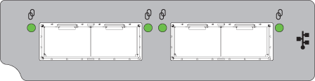
LED DESCRIPTION COLOR STATUS 
iSCSI 25Gb/10Gb link activity Green On—Connected, link is up Flashing—Link activity Off — Not connected or link is down
Figure 1: 25 Gb iSCSI Controller Port LEDs
-
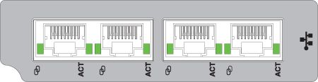
LED DESCRIPTION COLOR STATUS 
iSCSI 10Gbase-T link speed Green On—10 GbE link speed Amber On—1 GbE link speed None Off—Not connected or link is down ACT iSCSI 10Gbase-T link activity Green On—Connected, link is up Flashing—Link activity Off — Not connected or link is down
Figure 2: 10 Gb iSCSI Base-T Port LEDs
View port status using PowerVault Manager
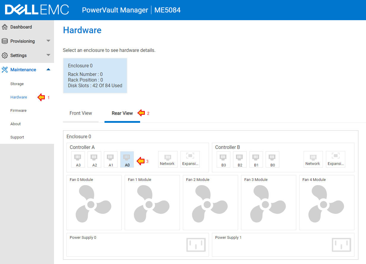
- The Hardware panel (Maintenance > Hardware) shows the system hardware configuration.
- Click the Rear View tab.
- Click each port in turn to view specific details about each port. Scroll down to view each ports link status, link speed, and connected media details where applicable.
-
-
Figure 3: Select Rear View and click each port in turn to see current port status.
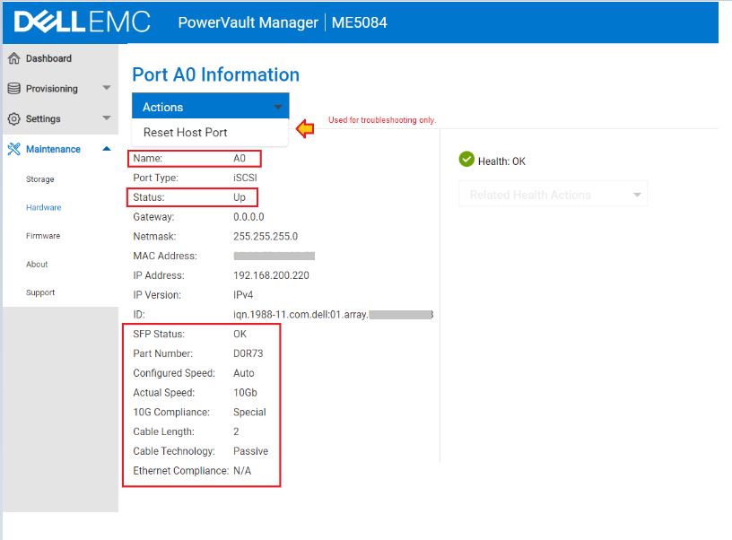
Figure 4: Details are shown about a specific port.
- Actions, Reset Host Port should only be used as a troubleshooting step when there is no link and cable is connected.
View port status using PowerVault Command-Line Interface
- Open an SSH session to either controllers management IP address using a terminal application such as PuTTY
.
- Run the following commands:
| Command | Description |
show system |
Check that the system health is OK and both controller modules (where applicable) are seen. |
show alerts unresolved |
Unresolved alerts may help explain the symptoms being experienced. |
show ports detail |
List the controller module ports link status and details of connected media. |
show host-port-statistics |
View port statistics to determine if I/O is going through the port. |
NOTE: The following command output is shortened to show the output of one port.
# show ports
Ports Media  Target ID                                   Status        Speed(A) Health     Reason Action
---------------------------------------------------------------------------------------------------------
A0    iSCSI  iqn.1988-11.com.dell:01.array.xxxxxxxxxxxx  Up            10Gb     OK

   Port Details
   ------------
   IP Version: IPv4
   IP Address: 192.168.200.220
   Gateway: 0.0.0.0
   Netmask: 255.255.255.0
   MAC: 00:xx:xx:xx:xx:xx

# show ports detail
Ports Media  Target ID                                   Status        Speed(A) Health     Reason Action
---------------------------------------------------------------------------------------------------------
A0    iSCSI  iqn.1988-11.com.dell:01.array.xxxxxxxxxxxx  Up            10Gb     OK

   Port Details
   ------------
   IP Version: IPv4
   IP Address: 192.168.200.220
   Gateway: 0.0.0.0
   Netmask: 255.255.255.0
   MAC: 00:xx:xx:xx:xx:xx
   SFP Status: OK
   Part Number: D0R73
   10G Compliance: Special
   Ethernet Compliance: N/A
   Cable Technology: Passive
   Cable Length: 2
To determine if iSCSI traffic is passing on the ports, use the command: show host-port-statistics
# show host-port-statistics
Durable ID           Bps                IOPS             Reads            Writes           Data Read        Data Written     Queue Depth      I/O Resp Time    Read Resp Time   Write Resp Time  Reset Time
---------------------------------------------------------------------------------------------------------------------------------------------------------------------------------------------------------------------------
hostport_A0          0B                 0                154              244              3677.6KB         48.5MB           0                0                0                0                2022-06-24 17:43:15
hostport_A1          0B                 0                151              245              3403.2KB         48.5MB           0                0                0                0                2022-06-24 17:43:15
hostport_A2          0B                 0                0                0                0B               0B               0                0                0                0                2022-06-24 17:43:15
hostport_A3          0B                 0                0                0                0B               0B               0                0                0                0                2022-06-24 17:43:15
hostport_B0          0B                 0                9                0                12.2KB           0B               0                0                0                0                2022-06-24 17:43:31
hostport_B1          0B                 0                9                0                12.2KB           0B               0                0                0                0                2022-06-24 17:43:31
hostport_B2          0B                 0                0                0                0B               0B               0                0                0                0                2022-06-24 17:43:31
hostport_B3          0B                 0                0                0                0B               0B               0                0                0                0                2022-06-24 17:43:31
---------------------------------------------------------------------------------------------------------------------------------------------------------------------------------------------------------------------------
Success: Command completed successfully. (2022-07-03 21:26:52)
25 Gb Ethernet considerations
25 Gb Ethernet introduces new considerations that do not exist when troubleshooting 10 Gb and 1 Gb Ethernet link speeds.
- The 25Gb standard IEEE 802.3by was approved in June 2016. Components must comply with this standard to operate reliably at 25 Gb.
- 25 Gb Ethernet uses autonegotiation and forward error correction (FEC). You may observe different behaviors with link negotiation, for more information see Dell 25 Gb Ethernet autonegotiation technote.
- The SFP28 transceiver form factor is plug compatible with SFP+ network ports, and most SFP28 transceivers negotiate 10 Gb link speeds.
- On site there may be a mix of 10 Gb and 25 Gb transceivers and cables. These are plug compatible and look the same therefore examine the labels and part numbers on transceivers or cables used to ensure that they are rated for 25 Gb. The range of Dell supplied part numbers along with models are listed in the PowerVault ME5 support matrix under the sections iSCSI transceivers and Supported cables.
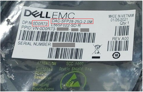
Figure 5: Dell Part Number Shown in Cable Packaging
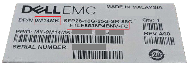
Figure 6: Dell Part Number and Model Shown on Transceiver Packaging
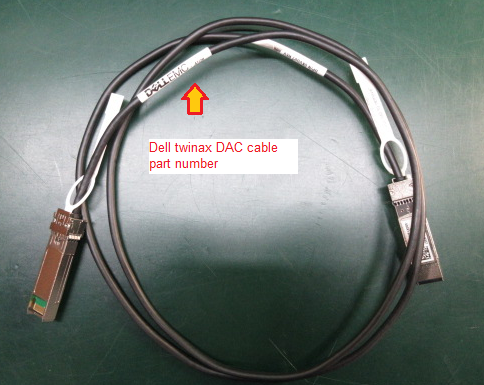
Figure 7: Dell Part Number Location on DAC Cable

Figure 8: Dell Supplied SFP28 Transceiver Showing Part Number, Model, and PPID.
Fault isolation
There is no Ethernet link between the PowerVault ME5 controller port and either the switch port or host NIC port.
Connect the cables or transceivers to the same devices to verify if a link comes up. You do not need a cross-over cable 1 Gb, 10 Gb, and 25 Gb ports support AutoMDI-X.
- Connect the transceiver and fiber optic cable or DAC cable using a free port on controller A to another free port on controller B (for example, connect controller A port 0 to controller B port 0).
- If the link comes up, check what speed it negotiates with. This may be a useful way to verify the supported link speed of the cable or fiber optic transceiver.
- If the link does not come up, swap test with other cable, transceiver, or port combination.
NOTE: Pay attention to potential contamination of the connectors when using fiber optic cable and transceivers. A combination of dust, oil, sweat, or scratches on the ends of connectors can impede light refraction resulting in no link or a poor quality signal that causes poor performance under load.
- When using an Ethernet switch test, use the same method by connecting the cable from one port to another on the same switch. If there is no link, follow the switch vendors troubleshooting guide.
- If using a direct host connection between the ME5 controller module port and host port, connect the cable from one port to another on the same host NIC if the interface card has two or more ports. If there is no link, ensure that the operating system device driver is loaded and the ports are not disabled in the host operating system.
Ethernet switch specification recommendations for iSCSI traffic
There are many Ethernet switch vendors in the market. Dell does not maintain a compatibility list of Ethernet switches that support iSCSI traffic with the PowerVault ME5.
General requirements for switches to support iSCSI traffic.
- All switching components in the SAN must have active support contracts in place with the device vendor.
- Link level flow control (IEEE 802.3x) on ingress or inbound switch ports (also known as "Rx Flow Control" or "receive-side flow control" from the switch port’s point of view)
- Dynamic packet buffer management with a minimum of:
- 4 MB of shared packet buffer for 1 Gbps switches
- 9 MB of shared packet buffer for 10 Gbps switches
- 32 MB of shared packet buffer for 25 Gbps switches
- Ability to configure ports to immediate forwarding state for edge ports (may be known as "portfast" mode)
- Jumbo Frames (MTU 9000+ bytes) support if enabled on PowerVault ME5
PowerVault ME switch configurations are similar to SC series arrays, if you must lookup reference configuration material to configure a switch for iSCSI, see Dell article 124943: Switch configuration guides for SC Series or PS Series SANs.
Replication on PowerVault ME requires a switch.
Both PowerVault ME systems must be connected to the same fabric or network using a switch; direct connection between storage systems is not supported. Reference: Deployment guide - Cabling for replication (PDF)
Engaging Dell technical support for troubleshooting assistance
Dell technical support may ask you to supply some or all the following information depending on the scope of the issue.
- Support bundle from the PowerVault ME5. (required)
Instructions to gather or send support logs for the PowerVault ME5 is found in Dell article 196715: ME5: How to collect PowerVault support logs
- Particulars of the cables or transceivers used (required)
For DAC twinax cables, Dell technical support wants to know the cable vendor, part number, and length.
For transceivers include a photo of the SFP+ or SFP28 transceiver label showing the part numbers and model used at either end of the connection.
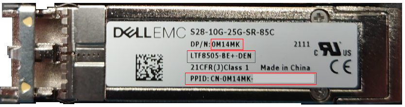
Figure 9: Dell Supplied SFP28 Transceiver Showing Part Number, Model, and PPID (2).
- Details or logs from the connected Ethernet switch used for iSCSI traffic (where requested)
In general, Dell Technical Support wants to know the switch model, switch firmware, ports used on the Ethernet switch that are connected to the PowerVault ME5, media inventory, and error statistics for ports with connected media and switch event logs that may indicate any issues such as spanning tree loops or insertion of media and link detection status and importantly whether the switch port used is enabled.
For most switch models, administrators can open an SSH session using a terminal application such as PuTTY and capture the output of the commands listed below to text file.
The syntax of the following commands varies depending on switch vendor and model. See the vendors documentation to find the equivalent command syntax for your Ethernet switch model.
| Dell PowerSwitch | CISCO Catalyst | Description |
show tech-support | no-more |
term len 0show tech-support |
This command is a collection of several diagnostic commands used by technical support to examine switch configuration and port state. |
show inventory media | no-more |
term len 0show interfaces transceivershow interfaces transceiver detail |
Displays information about transceivers that have digital optical monitoring (DOM) enabled |
show lldp neighbors | no-more |
show lldp neighbors |
Display LLDP neighbor information for all interfaces or a specified interface. The feature may not be enabled on all switch firmware. |
show mac-address-table | no-more |
show mac address-table |
Used to determine if an end device MAC address is being learned on a switch. |
- Details or logs from a connected host operating system (where requested)
In general, Dell technical support wants to know details about the network interface card (NIC) used, the device driver, and firmware used by the NIC and the OS port configuration.
It may be necessary to further review host operating system event logs and configurations to determine if recommended best configuration practices have been followed. Best practice information can also be found on Dell Technologies Info hub.
The following utilities can make operating system log gathering easier. Administrator-level access is required to run log gathering tools.
| Operating System | Utility | Description |
| VMware ESXi | vm-support | Gathers ESXi host diagnostic logs, see VMware article "vm-support" command in ESX/ESXi to collect diagnostic information |
| Linux | sosreport | Most Linux distributions include the sosreport utility. See Red Hat article What is a sos report and how to create one in Red Hat Enterprise Linux? |
| Windows Server | emcgrab | Dell article How To Run Grab On Microsoft Windows Hosts. |
NOTE: Some of these log files are larger than can be sent using email. Dell Technical Support engineers provide you with options to upload the files.
Affected Products
ME Series, Dell EMC PowerVault ME412 Expansion, Dell EMC PowerVault ME424 Expansion, Dell EMC PowerVault ME484, PowerVault ME5012, PowerVault ME5024, PowerVault ME5084Article Properties
Article Number: 000201155
Article Type: How To
Last Modified: 22 Apr 2025
Version: 12
Find answers to your questions from other Dell users
Support Services
Check if your device is covered by Support Services.