OptiPlex 7071 Tower Teardown/Removal guide for customer replaceable units (CRUs)
Riepilogo: This article is a guide to the removal of those parts of the Dell OptiPlex 7071 Towe desktop, that dell considers it OK for anyone to remove and replace.
Questo articolo si applica a
Questo articolo non si applica a
Questo articolo non è legato a un prodotto specifico.
Non tutte le versioni del prodotto sono identificate in questo articolo.
Sintomi
These guides will take you step by step through the safe removal of what are considered to be the Customer Replaceable Unit (CRU) parts of an OptiPlex 7071 Tower system. (CRUs are the parts of the system that shouldn't need an engineer to remove or replace.) The guides will also include pictures to reference what's involved.
Table of Contents:
Removal Guide
If these guides do not cover what you are looking to do, then you will want to reference your System Manual.
The article below provides information on safe practises you should take into consideration before working with electrical equipment.
Removal Instructions
 Note: Please click on the title of the section you want to open below, to see the contents.
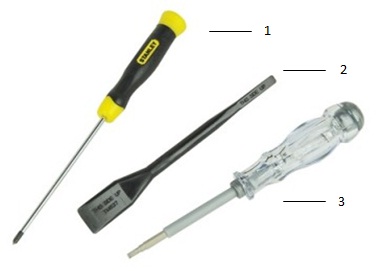
| 1 | Small Phillip's head screwdriver | 2 | Plastic Scribe |
| 3 | Small Flathead screwdriver |
 Note: Be aware that using a large Phillips or Flat Head screwdriver may result in damage to the head of the screws. This would make their removal impossible without speciality tools, that aren't available to our onsite engineers.
-
Pre-Removal Instructions Before removing the Side Panel Cover:
-
During installation or removal of any hardware always ensure all data is backed up properly
-
Disconnect any telephone, network, or USB cables from the computer
-
Disconnect the computer and all attached devices from their electrical outlets
-
-
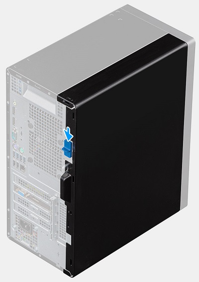
With the system on standing upright, push the blue release catch on the rear of the system down to unlock the cover panel from the chassis
-
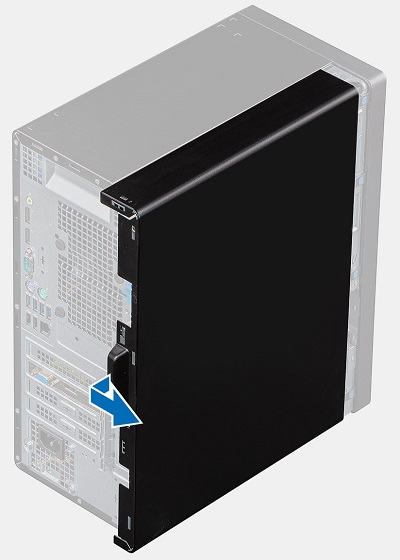
Pull the cover towards the rear of the chassis until the lugs on the cover release from the chassis and lift the cover off of the computer
-
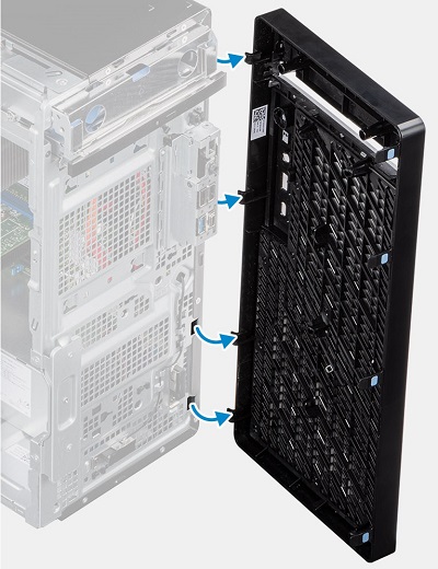
Pre-Removal Instructions Before removing the Front Bezel:
-
During installation or removal of any hardware always ensure all data is backed up properly
-
Disconnect any telephone, network, or USB cables from the computer
-
Disconnect the computer and all attached devices from their electrical outlets
-
Please remove the Side Panel Cover
-
-
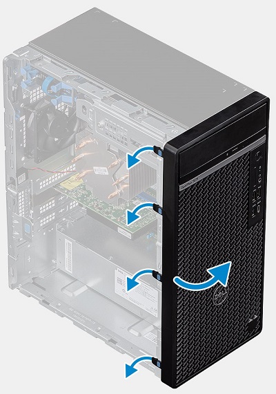
With the system standing upright, release the four (4) blue tabs down the left-hand side of the bezel and swing it towards the right-hand side of the system
-
When the bezel gets to 90 degrees from the chassis, lift it off of the computer
-
Pre-Removal Instructions Before removing the Hard Disk Drive (HDD):
-
During installation or removal of any hardware always ensure all data is backed up properly
-
Disconnect any telephone, network, or USB cables from the computer
-
Disconnect the computer and all attached devices from their electrical outlets
-
Please remove the Side Panel Cover and Front Bezel
-
-
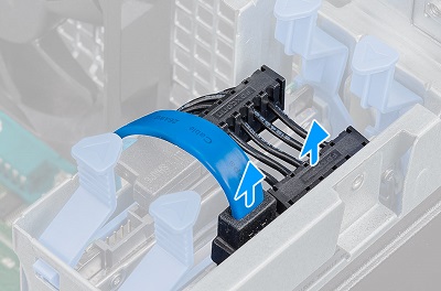
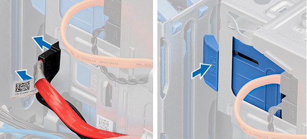
The 2.5" HDD bays are located in the top left-hand side corner of the system. Disconnect the data and power cable from the rear of the HDD
-
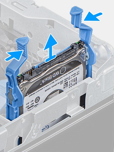
Squeeze the blue release table on either side of the HDD together and pull the HDD out of the system
-
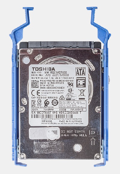
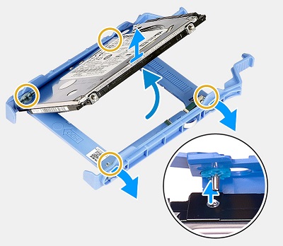
Pry the hard-drive bracket off along one edge of the HDD to release the tabs on the assembly from the slots on the hard drive.
-
Lift and remove the hard drive out of the hard-drive bracket.
-
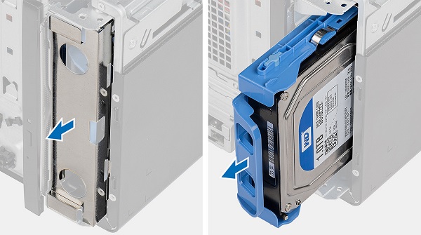
The 3.5" drive bay is located above the slim optical drive in the top right-hand side corner of the system, place the system on its side and disconnect the data and power cables from the rear of the HDD. Push the Blue release tab down to unlock the HDD assembly
-
Pop the ESD blanking plate out the front of the chassis and push the HDD assembly out the front of the system
-
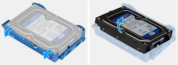
Pull one edge of the bracket away from the HDD to release the securing studs and pull the bracket off of the HDD
-
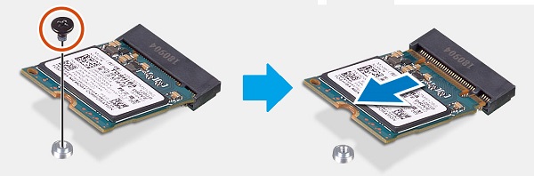
Pre-Removal Instructions Before removing the M.2 SSD/Intel Optane Memory Card:
-
During installation or removal of any hardware always ensure all data is backed up properly
-
Disconnect any telephone, network, or USB cables from the computer
-
Disconnect the computer and all attached devices from their electrical outlets
-
Please remove the Side Panel Cover
-
-
The M.2 connector is located between the CPU and the expansion card slots in the middle of the system. Remove the single screw which secures the end of the M.2 card to the chassis
-
When the card pops up at an angle, pull the card out of the connector and out of the PC
-
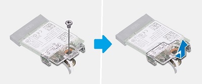
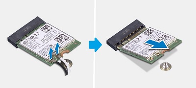
Pre-Removal Instructions Before removing the M.2 WLAN Wireless Card:
-
During installation or removal of any hardware always ensure all data is backed up properly
-
Disconnect any telephone, network, or USB cables from the computer
-
Disconnect the computer and all attached devices from their electrical outlets
-
Please remove the Side Panel Cover
-
-
The M.2 WLAN card is located between the Memory and the front of the system. Remove the single screw which secures the end of the M.2 card to the chassis and slide the Wireless card bracket off the end of the card
-
Disconnect the antenna cables from the end of the card (little press studs secure the connectors) and While the card is popped up at an angle, pull the card out of the connector and out of the PC
-
Pre-Removal Instructions Before removing the Slim Optical Drive (ODD):
-
During installation or removal of any hardware always ensure all data is backed up properly
-
Disconnect any telephone, network, or USB cables from the computer
-
Disconnect the computer and all attached devices from their electrical outlets
-
Please remove the Side Panel Cover and Front Bezel
-
-
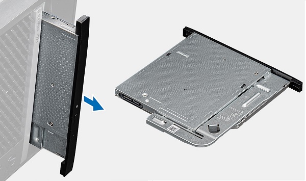
The slim optical drive is located in the top right-hand corner of the system, once the data and power cables are removed, push down on the silver release table to unlock the drive
-
Push the drive out the front of the system
-
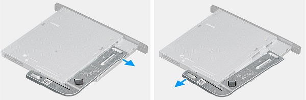
Pry the ODD bracket off of the drive, you will need this for the replacement drive
-
Pre-Removal Instructions Before removing the Memory:
-
During installation or removal of any hardware always ensure all data is backed up properly
-
Disconnect any telephone, network, or USB cables from the computer
-
Disconnect the computer and all attached devices from their electrical outlets
-
Please remove the Side Panel Cover
-
-
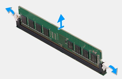
The memory is located in the centre of the system, pull the tabs on either side of the DIMM apart to release the memory DIMM
-
Lift the DIMM up and out of the slot and the PC
 Note: Please repeat Steps 2 and 3 for any additional Memory DIMMs located in the system.
-
Pre-Removal Instructions Before removing the Speaker:
-
During installation or removal of any hardware always ensure all data is backed up properly
-
Disconnect any telephone, network, or USB cables from the computer
-
Disconnect the computer and all attached devices from their electrical outlets
-
Please remove the Side Panel Cover and System Fan
-
-
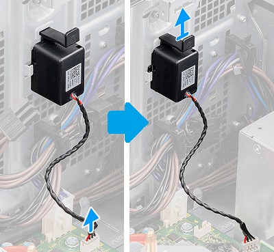
The speaker is located on the inside of the front face of the system in front of the PSU, disconnect the cable from the motherboard
-
Press the release latch down and lift the speaker up and out of the PC
-
Pre-Removal Instructions Before removing the CPU Cooling Fan:
-
During installation or removal of any hardware always ensure all data is backed up properly
-
Disconnect any telephone, network, or USB cables from the computer
-
Disconnect the computer and all attached devices from their electrical outlets
-
Please remove the Side Panel Cover
-
-
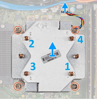
The CPU cooling fan is located in the middle of the system, disconnect the fan cable from the motherboard. Starting with position 4 and then going to 3, then 2, then 1, loosen the captive screws that secure the fan and heatsink to the motherboard
-
Lift the cooling fan and heatsink assembly out of the PC
-
Pre-Removal Instructions Before removing an Expansion Card:
-
During installation or removal of any hardware always ensure all data is backed up properly
-
Disconnect any telephone, network, or USB cables from the computer
-
Disconnect the computer and all attached devices from their electrical outlets
-
Please remove the Side Panel Cover and System Fan
-
-
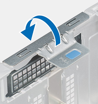
The expansion card slots are located between the PSU and the CPU cooling fan, release the retention clip from its securing hook and swing it fully open
-
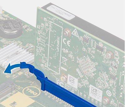
Check if there is a securing tab at the back edge of any occupied slots on the motherboard, if its there move it to an unlocked position
-
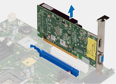
Lift the card straight up and out of the PC
-
Pre-Removal Instructions Before removing the Coin Cell Battery :
-
During installation or removal of any hardware always ensure all data is backed up properly
-
Disconnect any telephone, network, or USB cables from the computer
-
Disconnect the computer and all attached devices from their electrical outlets
-
Please remove the Side Panel Cover and any Expansion Cards
-
-
The coin cell battery is located between the expansion card slots and the front of the system, once any cards are removed, using a plastic scribe push the coin cell battery release lever
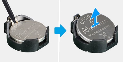
-
Lift the battery out of the PC
-
Pre-Removal Instructions Before removing the PSU Power Supply Unit:
-
During installation or removal of any hardware always ensure all data is backed up properly
-
Disconnect any telephone, network, or USB cables from the computer
-
Disconnect the computer and all attached devices from their electrical outlets
-
Please remove the Side Panel Cover, Cooling Fan and any Expansion Cards
-
-
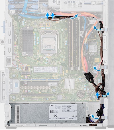
The PSU is located at the bottom left-hand corner of the chassis, disconnect and un-route the power cables running around the front of the system to the motherboard, fans and drives
-
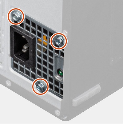
Remove the three (3) screws from the rear of the PSU
-
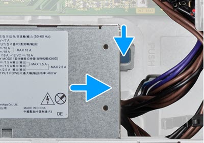
Push down on the silver release catch on the right-hand side of the PSU and push the PSU towards the front of the system
-
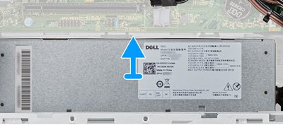
Push the PSU towards the motherboard and lift it up and out of the PC
| If you require further assistance, please contact technical support. | |
| Contact Us | |
Causa
N/A
Risoluzione
N/A
Prodotti interessati
OptiPlex 7071 TowerProprietà dell'articolo
Numero articolo: 000134600
Tipo di articolo: Solution
Ultima modifica: 29 set 2023
Versione: 6
Trova risposta alle tue domande dagli altri utenti Dell
Support Services
Verifica che il dispositivo sia coperto dai Servizi di supporto.